CMS60D User Manual
Pulse Oximeter
Contec Medical Systems Co., Ltd.
Address:No.112 Qinhuang West Street, Economic &Technical Development Zone,
Qinhuangdao, Hebei Province, PEOPLE’S REPUBLIC OF CHINA
Tel: +86-335-8015430
Fax: +86-335-8015588
Technical support: +86-335-8015431
Website: http://www.contecmed.com
EC REPRESENTATIVE
Shanghai International Holding Corp. GmbH(Europe)
Address: Eiffestrasse 80, 20537, Hamburg, Germany
Tel: +49-40-2513175
Fax: +49-40-255726
CMS2.782.089.01(BT.USB)(CE)ESS/1.0 1.4.01.01.852 2022.12
User Notice
Dear users, thank you very much for purchasing the Pulse Oximeter (hereinafter referred to as device).
This Manual is written and compiled in accordance with the council directive MDD93/42/EEC for medical devices
and harmonized standards. In case of modifications and software upgrades, the information contained in this
document is subject to change without notice.
It is a medical device, which can be used repeatedly.
The Manual describes, in accordance with the device’s features and requirements, main structure, functions,
specifications, correct methods for transportation, installation, usage, operation, repair, maintenance and storage,
etc. as well as the safety procedures to protect both the user and device. Refer to the respective chapters for details.
Please read the User Manual carefully before using this device. The User Manual which describes the operating
procedures should be followed strictly. Failure to follow the User Manual may cause measuring abnormality,
device damage and human injury. The manufacturer is NOT responsible for the safety, reliability and performance
issues and any monitoring abnormality, human injury and device damage due to users' negligence of the operation
instructions. The manufacturer’s warranty service does not cover such faults.
Owing to the forthcoming renovation, the specific products you received may not be totally in accordance with the
description of this User Manual. We would sincerely regret for that.
Our company has the final interpretation to this manual. The content of this manual is subject to change without
prior notice.
Warnings
Remind that it may cause serious consequences to tester, user or environment.
Explosive hazard—DO NOT use the device in environment with inflammable gas such as anesthetic.
DO NOT use the device while examining by MRI or CT, as the induced current may cause burn.
Do not take the information displayed on the device as the sole basis for clinical diagnosis. The device is only
used as an auxiliary means in diagnosis. And it must be used in conjunction with doctor’s advice, clinical
manifestations and symptoms.
The maintenance to the device can only be performed by qualified service personnel specified by
manufacturer, Users are not permitted to maintain or refit the device by themselves.
Uncomfortable or painful feeling may appear if using the device ceaselessly, especially for the
microcirculation disturbance users. It is not recommended that the sensor is used on the same finger for more
than 2 hours.
For some special users who need a more careful inspection on the test site, please don’t place the device on the
edema or tender tissue.
Please do not stare at the red and infrared light emitter (the infrared light is invisible) after turning on the
device, including the maintenance staff, as it may be harmful to the eyes.
The device contains silicone, PVC, TPU, TPE and ABS materials, whose biocompatibility has been tested in
accordance with the requirements in ISO 10993-1, and it has passed the recommended biocompatibility test.
The person who is allergic to silicone, PVC, TPU, TPE or ABS can not use this device.
The disposal of scrap device, its accessories and packaging should follow the local laws and regulations, to
avoid polluting to the local environment. And the packaging materials must be placed in the region where the
children are out of reaching.
The device can not be used with the equipment not specified in the Manual. Only the accessories appointed or
recommended by the manufacturer can be used, otherwise it may cause injury to the tester and operator or
damage to the device.
The SpO2 probe accompanied is only suitable for using with the device. The device can only use the SpO2
probe described in the Manual, so the operator has the responsibility to check the compatibility between the
device and the SpO2 probe before using, incompatible accessories may cause device performance degradation,
device damage or patient injury.
Do not reprocess the accompanying SpO2 probe.
Check the device before use to make sure that there is no visible damage that may affect user’s safety and
device performance. When there is obvious damage, please replace the damaged parts before use.
When the message “Sensor Off” or “Sensor Fault” appears on the screen, it indicates that the SpO2 probe is
disconnected or line fault occurs. Check the connection of the SpO2 probe and whether there is damage for the
probe, if necessary, please replace the probe to avoid risks. The probe fault will not result in a safety hazard.
Functional testers can not be used to assess the accuracy of the SpO2 probe and Pulse Oximeter.
Some functional testers or patient simulators can be used to verify whether the device works normally, for
example, INDEX-2LFE Simulator (software version: 3.00), please refer to the Manual for the detailed
operation steps.
Some functional testers or patient simulators can measure the accuracy of the device copied calibration curve,
but they can not be used to evaluate the device accuracy.
When using the device, please keep it away from the equipment which can generate strong electric field or
strong magnetic field. Using the device in an inappropriate environment may cause interference to the
surrounding radio equipment or affect its working.
When storing the device, keep it away from children, pets and insects to avoid affecting its performance.
Do not place the device in places exposed to direct sunlight, high temperature, humidity, dust, cotton wool or
easy to splash water, to avoid affecting its performance.
The measured accuracy will be affected by the interference of electrosurgical equipment.
When several products are used on the same patient simultaneously, danger may occur which is arisen from
the overlap of leakage current.
CO poisoning will appear excessive estimation, so it is not recommended to use the device.
This device is not intended for treatment.
The intended operator of the device may be a patient.
Avoid maintaining the device during using.
Users should read the product manual carefully before use and operate according to the requirements.
1 Overview
The oxygen saturation is the percentage of HbO2 in the total Hb in the blood, so-called the O2 concentration in the blood, it is an
important physiological parameter for the respiratory and circulatory system. A number of diseases related to respiratory system
may cause the decrease of SpO2 in the blood, furthermore, some other causes such as the malfunction of human body's
self-adjustment, damages during surgery, and the injuries caused by some medical checkup would also lead to the difficulty of
oxygen supply in human body, and the corresponding symptoms would appear as a consequence, such as vertigo, impotence,
vomit etc. Serious symptoms might bring danger to human's life. Therefore, prompt information of patients' SpO2 is of great help
for the doctor to discover the potential danger, and is of great importance in the clinical medical field.
Insert the finger when measuring, the device will directly display the SpO2 value measured, it has a higher accuracy and
repeatability.
1.1 Features
A. Easy to use.
B. Small in volume, light in weight, convenient to carry.
C. Low power consumption.
1.2 Intended purpose
The Pulse Oximeter can be used in measuring the pulse oxygen saturation and pulse rate through finger. The product is suitable for
being used in family, hospital, oxygen bar, community healthcare, physical care in sports (It can be used before or after doing
sports, and it is not recommended to use the device during the process of having sport) and etc.
1.3 Environment requirements
Storage Environment
a) Temperature: -40 ℃ ~ + 60 ℃
b) Relative humidity: ≤ 95%
c) Atmospheric pressure: 500 hPa ~ 1060 hPa
Operating Environment
a) Temperature: +10 ℃~ + 40 ℃
b) Relative Humidity: ≤ 75%
c) Atmospheric pressure: 700 hPa ~ 1060 hPa
1.4 Precautions
1.4.1 Attention
Point out conditions or practices that may cause damage to the device or other properties.
Before using the device, make sure that it locates in normal working state and operating environment.
In order to get a more accurate measurement, it should be used in a quiet and comfortable environment.
When the device is carried from cold or hot environment to warm or humid environment, please do not use it immediately,
wait four hours at least is recommended.
If the device is splashed or coagulated by water, please stop operating.
DO NOT operate the device with sharp things.
High temperature, high pressure, gas sterilizing or immersion disinfection for the device is not permitted. Refer to User
Manual in the relative chapter (6.1) for cleaning and disinfection. Please take out the internal battery before cleaning and
disinfection.
The device is suitable for children and adult.
The device may not be suitable for all users, if you can't get a satisfactory result, please stop using it.
Data averaging and signal processing have a delay in the upgrade of SpO2 data values. When the data update period is less
than 30 seconds, the time for obtaining dynamic average values will increase, which is arisen from signal degradation, low
perfusion or other interference, it depends on the PR value.
The device has 3-year service life, date of manufacture see the label.
The expected service life of the attached parts or accessories of the equipment is two year.
If the shelf life is less than the expected service life, the shelf life of the attached parts or accessories of the equipment is
two year.
The device does not provide over-limit alarm function for SpO2 and PR, so it is inapplicable for using in the place where
need such function.
This device has the function of prompting, users can check on this function according to chapter 5.5.1 as a reference.
The device has the function of limits prompting, when the measured data is beyond the highest or lowest limit, the device
would start prompting automatically on the premise of the prompting function is on.
The device has the function of prompting, this function can either be paused, or closed for good. This function could be
turned on through menu operation if you need. Please check the chapter 5.5.1 as a reference.
The device hasn't low-voltage alarm function, it only shows the low-voltage, please change the battery when the battery
voltage is used up.
The maximum temperature at the SpO2 probe -tissue interface should be less than 41℃ which is measured by the
temperature tester.
During measuring, when abnormal conditions appear on the screen, please pull out your finger and reinsert it to measure
again.
If some unknown error appears during measuring, remove the battery to terminate operating.
Do not contort or drag the wire of the device.
The plethysmographic waveform is not normalized, as a signal inadequacy indicator, when it is not smooth and stable, the
accuracy of the measured value may degrade. When it tends to be smooth and stable, the measured value read is the
optimal and the waveform at this time is also the most standard.
If necessary, please visit our official website to get the information about SpO2 probe that can be used with this device.
If the device or component is intended for single-use, then the repeated use of these parts will pose risks on the parameters
and technical parameters of the equipment known to the manufacturer.
If necessary, our company can provide some information (such as circuit diagrams, component lists, illustrations, etc.), so
that the qualified technical personnel of the user can repair the device components designated by our company.
The measured results will be influenced by the external colouring agent (such as nail polish, colouring agent or color skin
care products, etc.), so don't use them on the test site.
As to the fingers which are too cold or too thin or whose fingernail is too long, it may affect the measured results, so please
insert the thicker finger such as thumb or middle finger deeply enough into the probe when measuring.
The finger should be placed correctly (see Attached figure 5), as improper installation or improper contact position for
sensor will influence the measurement.
The light between the photoelectric receiving tube and the light-emitting tube of the device must pass through the subject’s
arteriole. Make sure the optical path is free from any optical obstacles like rubberized fabric, to avoid inaccurate results.
Excessive ambient light may affect the measured results, such as surgical light (especially xenon light sources), bilirubin
lamp, fluorescent lamp, infrared heater and direct sunlight, etc. In order to prevent interference from ambient light, make
sure to place the sensor properly and cover the sensor with opaque material.
Frequent movement (active or passive) of the subject or severe activity can affect the measured accuracy.
The SpO2 probe should not be placed on a limb with the blood pressure cuff, arterial ductus or intraluminal tube.
The measured value may be inaccurate during defibrillation and in a short period after defibrillation, as it has not
defibrillation function.
The device has been calibrated before leaving factory.
The device is calibrated to display functional oxygen saturation.
The equipment connected with the Oximeter interface should comply with the requirements of IEC 60601-1.
1.4.2 Clinical restriction
A. As the measure is taken on the basis of arteriole pulse, substantial pulsating blood flow of subject is required. For a subject
with weak pulse due to shock, low ambient/body temperature, major bleeding, or use of vascular contracting drug, the SpO2
waveform (PLETH) will decrease. In this case, the measurement will be more sensitive to interference.
B. The measurement will be influenced by intravascular staining agents (such as indocyanine green or methylene blue), skin
pigmentation.
C. The measured value may be normal seemingly for the tester who has anemia or dysfunctional hemoglobin(such as
carboxyhaemoglobin (COHb), methaemoglobin (MetHb) and sulfhaemoglobin (SuHb)), but the tester may appear hypoxia, it is
recommended to perform further assessment according the clinical situations and symptoms.
D. Pulse oxygen only has a reference meaning for anemia and toxic hypoxia, as some severe anemia patients still show better
pulse oxygen measured valued.
E. Contraindication:
a. The person who is allergic to silicone, PVC, TPU TPE or ABS can not use this device.
b. The damaged skin tissue can’t be measured.
c. During cardiopulmonary resuscitation.
d. When the patient is hypovolemic.
e. For assessing the adequacy of ventilatory support.
f. For detecting worsening lung function in patients on a high concentration of oxygen.
1.5 Clinical indications
The Pulse Oximeter can be used in measuring the pulse oxygen saturation and pulse rate through finger.
2 Principle
Figure 1 Operating principle
An experience formula of data processing is established taking use of Lambert Beer Law according to Spectrum Absorption
Characteristics of Reductive Hemoglobin (Hb) and Oxyhemoglobin (HbO2) in red light & near-infrared light zones. On the basis
of the principle of Photoelectric Oxyhemoglobin Inspection Technology and Photoplethysmography technology, it uses two light
beams of different wavelengths to irradiate the human fingertip to obtain the measurement information from the photosensitive
element, after processed by the electronic circuits and microprocessor, displays the measured results on the screen.
3 Functions
A. SpO2 value display
B. PR value and bar graph display
C. Pulse waveform display
D. Low-voltage indication: Low-battery indication: low-battery indication appears when the battery voltage is too low to work
E. Screen brightness can be changed
F. Pulse sound indication
G. Voice prompt for over-limit, probe off /finger-out and low battery
H. With SpO2 value and pulse rate value record function, the stored data can be uploaded to computer
I. It can be connected with an external oximeter probe
J. Real-time data can be transmitted to computer
K. Review function
L. Clock function
4 Installation
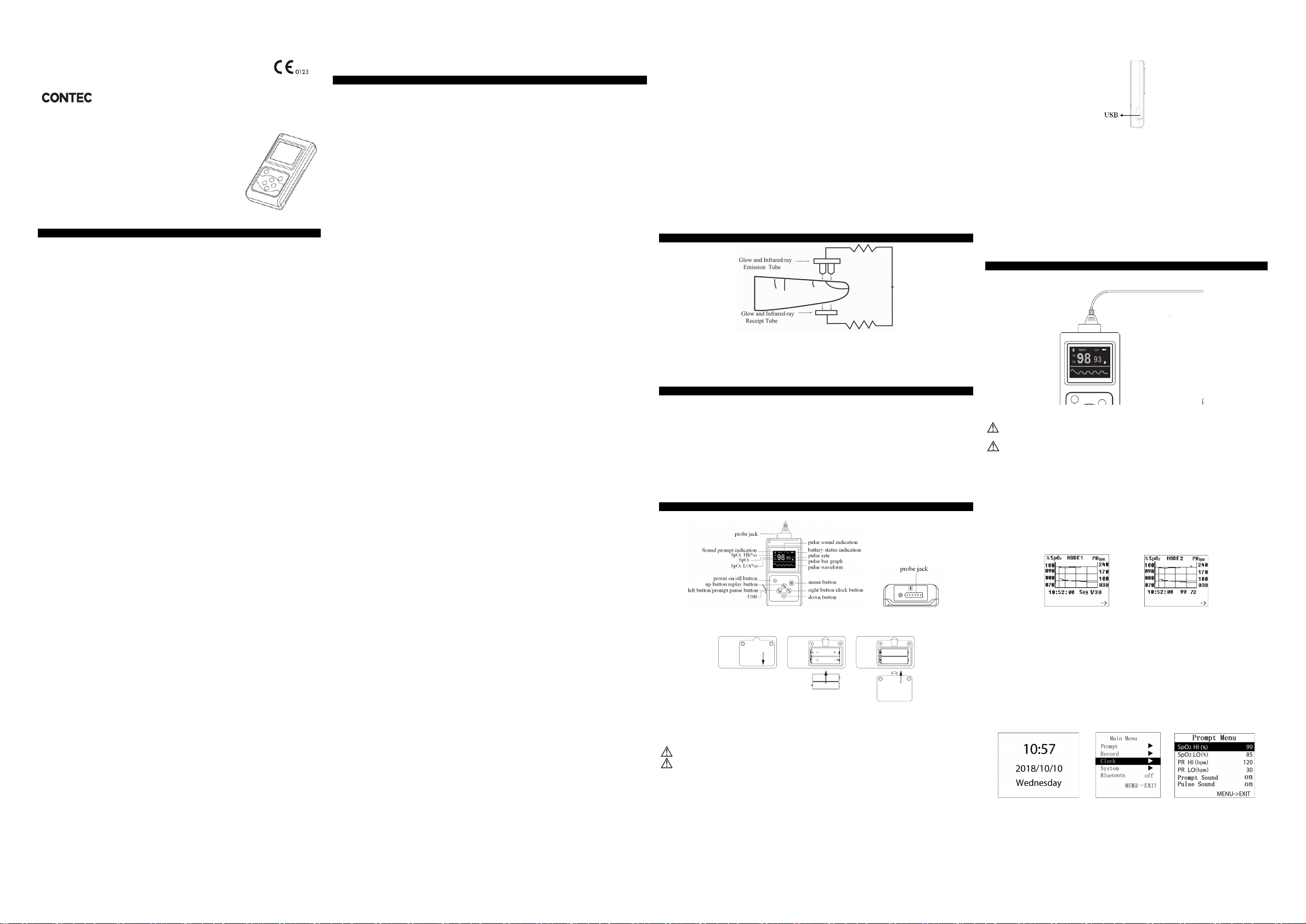
4.1 Appearance
Figure 2. Front and top appearance
4.2 Battery installation
Figure 3. Batteries Installation
A. Refer to Figure 3. Use a screwdriver to unscrew the two screws from the battery compartment on the back of the product and
open the back cover of the battery compartment.
B. Insert the two AA size batteries properly in the right direction.
C. Close the battery back cover, screw on the screw.
Please take care when you insert the batteries, for the improper insertion may damage the device.
Please replace two new batteries of the same kind at the same time.
4.3 Probe installation
Inserting the SpO2 probe of the pulse oximeter in the probe jack, use a screwdriver to screw the screws (The probe is limited to
the one that is provided by our company; and can't be replaced with the similar one by other manufacturers)
4.4 USB port
It is used to connect a personal computer to export the trend data (see Figure 4).
Figure 4. USB Port
4.5 Structure, accessories and software description
A. Structure: main unit, SpO2 probe, USB cable, Bluetooth adapter (optional).
B. Accessories: one adult-oximeter probe, two AA size batteries (optional), one USB cable, one CD disk
(including PC software, optional), one User Manual, Bluetooth adapter (optional).
Please check the device and accessories according to the list to avoid that the device can not work normally.
C. Software description
Software name: CMS60D embedded software
Software specification: no
Release version: 2.0
Naming rule for version: V <Major enhancive software upgrade>.<Minor enhancive software
upgrade>.<Improvement software upgrade>
Involved algorithm: name: plethysmography; type: mature arithmetic
Purpose: be used to measure SpO2, pulse rate, etc.
Clinical function: calculate SpO2 and pulse rate values by collecting and processing the testee’ s pulse signal.
5 Operating guide
5.1 Application method
A. Put the finger into the probe. Refer to Figure 5.
Figure 5 Sketch map for finger placement
(The appearance of actual probe may be different with the one shown as Figure 5, please refer to the actual probe.)
when inserting the finger, the light emitting from the sensor must be directly irradiated to the side of
the fingernail.
In the process of using the tested finger had better not shake, the human body also had better not be in
motion state.
B. Long press the "power on/off " button, until the device turns on.
C. Do not shake the finger and keep the user in a stable state during the process.
D. The data can be read directly from the screen in the measure interface.
5.2 Pause sound prompt
A. Sound prompt, including: over-limit, low-battery, finger out, sensor off and sensor fault.
B. Under the measurement interface, turn on the sound prompt, when the sound prompt occurs, short press the
button to pause the sound prompt, and it will resume automatically after about 60s.
C. If you want to turn off the sound prompt permanently, please set it in menu.
5.3 Review Interface
A. In the measure interface, press "up button" to enter the Review Interface 1 directly, as shown in Figure 6:
Figure 6-1. Review Interface 1 Figure 6-2. Review Interface 2
B. In review interface, press "menu button" to switch between Review Interface 1 and Review Interface 2.
C. In Review Interface 1,the user can observe the trend waveform composed by storage data. Each screen can
show storage data for 105 seconds.The yellow line shows the SpO2 trend waveform,and the red line shows the PR
trend waveform.The time underside shows the starting time of displaying the date in the screen, press the “left
button” or “right button” to view the information on the previous or next page of the stored data trend chart.
D. The Review Interface 2 shown based in Review Interface 1, the stored SpO2 value and PR value in each second
can be observed here, the underside date from left to right marks time, SpO2 value, PR value. Press “left button” or
“right button” to display the blood oxygen and pulse of the previous or next second; Long press the “left button” or
“right button”, and the pulse and blood oxygen will be display with a data interval of 10 seconds.
E. Press "up button" to exit the review Interface, return to the measure interface.
5.4 Clock interface
In the measure interface, press the "right button" can enter the clock interface of Figure 7. Press the "right button"
again can return to the measure interface.
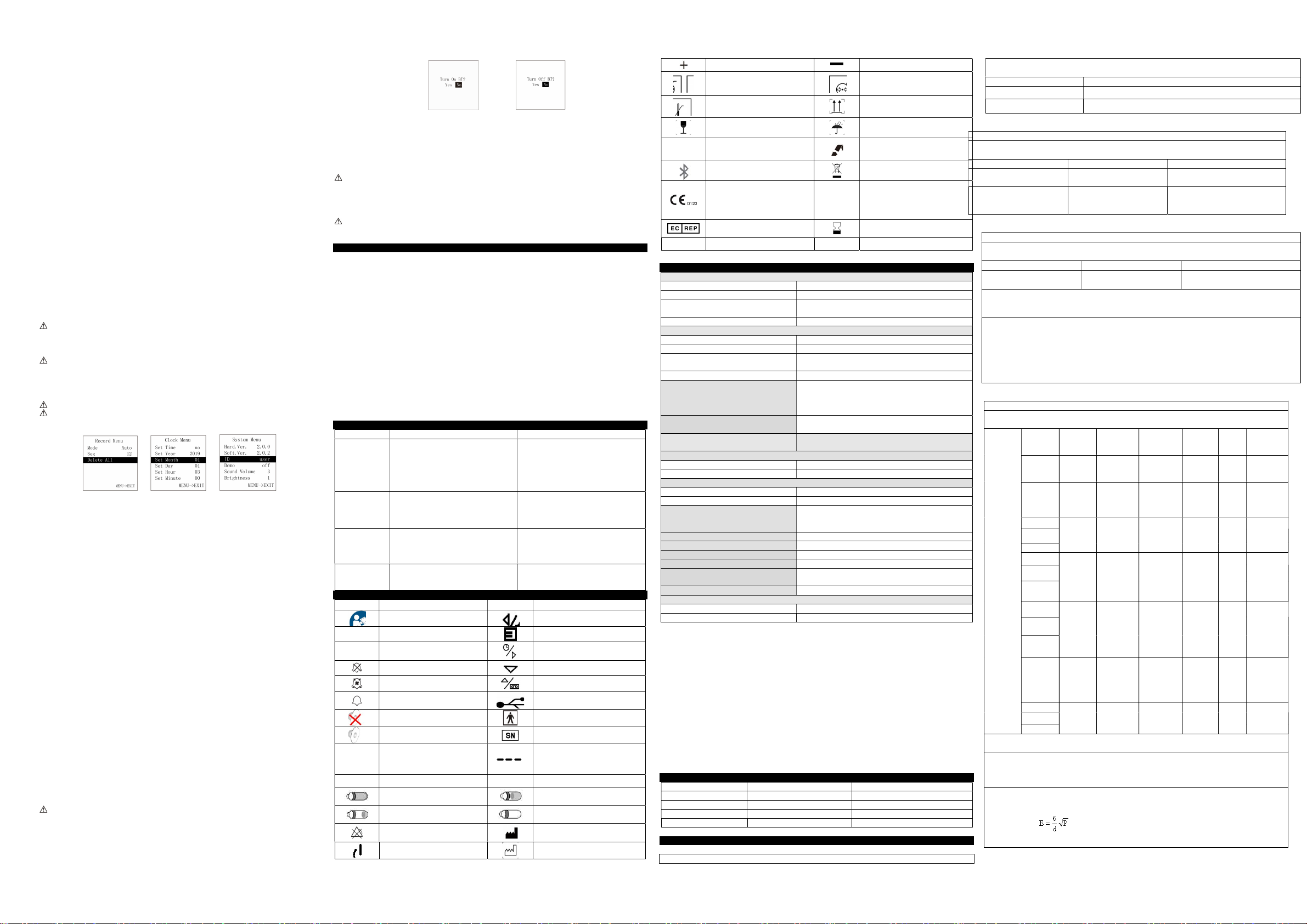
Figure 7. Clock interface Figure 8. Main Menu Figure 9 Setting for sound prompt
5.5 Menu operations:
In the measure interface, press the "menu button "can enter the menu of Figure 8. Users can adjust the setting
through the main menu, such as the sound prompt, record, clock, system, etc. can be set, methods are as
followings:
5.5.1 Sound prompt setting
Under main menu, press the "up button" or "down button" to select “Prompt”, then press the "up button" or "down