manuals.online logo
Brands
  1. Home
  2. •
  3. Brands
  4. •
  5. Contro l4
  6. •
  7. Keypad
  8. •
  9. Contro l4 C4-SKC User manual

Contro l4 C4-SKC User manual

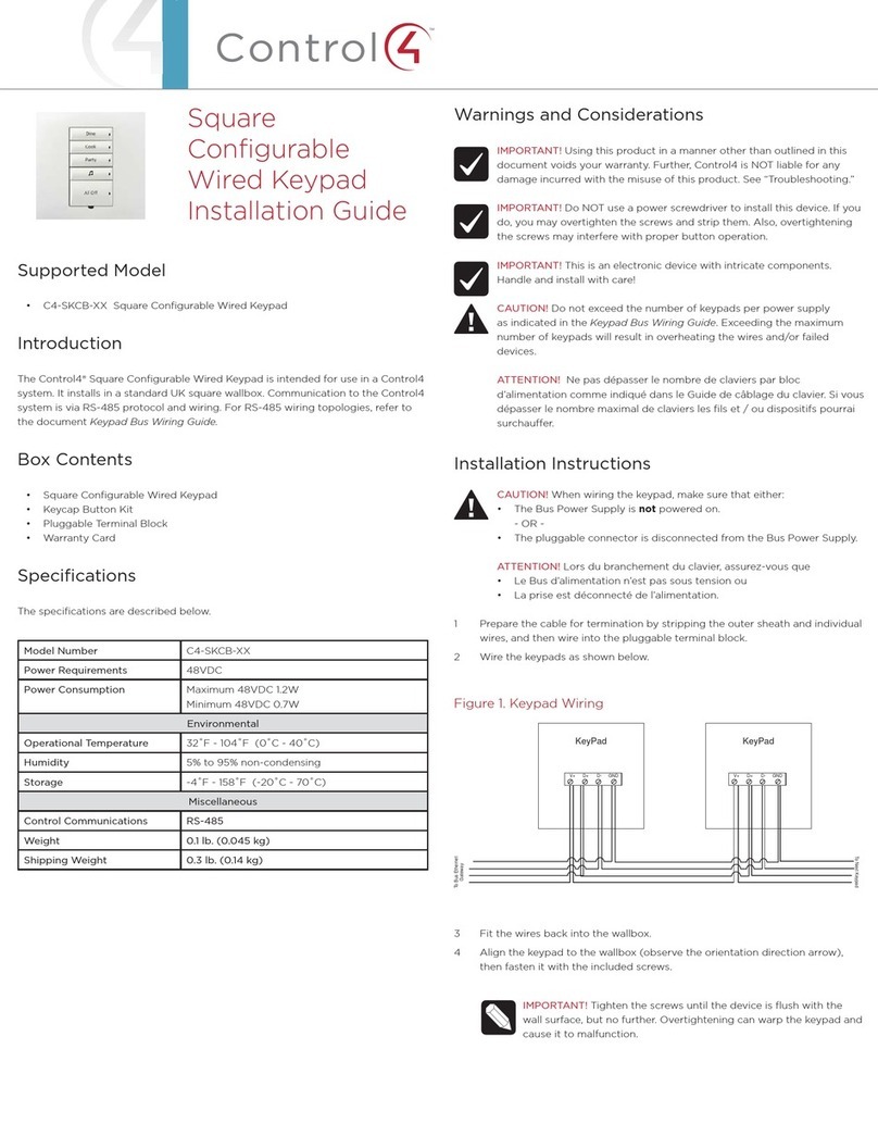
Square Wireless
Configurable Keypad
Installation Guide
Introduction
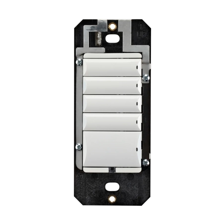
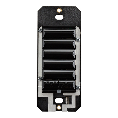
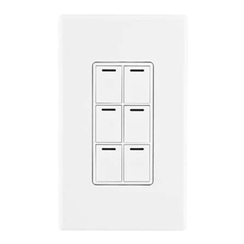
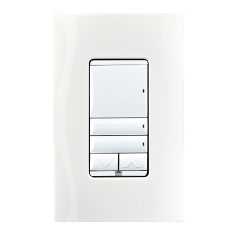
The Control4® Square Wireless Configurable Keypad is intended for use in a
Control4 system. It installs in a standard square (UK/China-style) or round (EU-
style) wall box using typical wiring standards and communicates to the Control4
system using a wireless connection.
Box contents
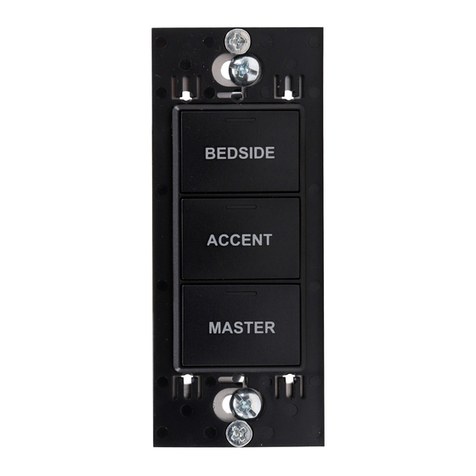
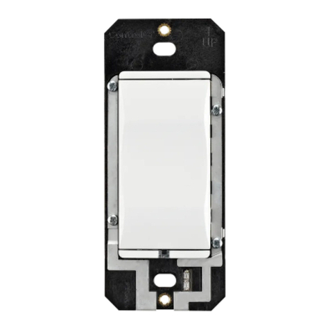
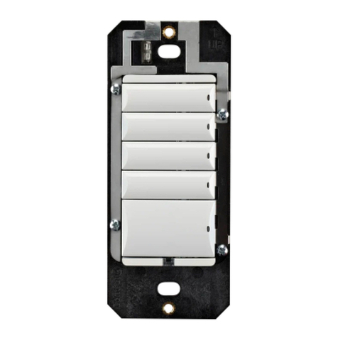
• Square Wireless Configurable Keypad
• Square Wireless Configurable Keypad Installation Guide (this document)
• M3.5 machine screws (2)
• M4.0 machine screws (2)
• M3.0 thread-cutting screws (2)
Specifications
The specifications are described below.
Model number C4-SKC
Power requirements 120VAC-277VAC +/-10% 50/60 Hz 36-48VDC
This device requires a neutral AC connection except
when used in combination with a Control4 Dimmer in a
multi-location scenario.
Power consumption 120V: 350mW
240V: 480mW
277V: 540mW
36VDC: 430mW
Environmental
Operational temperature 0˚C ~ 40˚C (32˚F ~ 104˚F)
Humidity 5% to 95% non-condensing
Storage -20˚C ~ 70˚C (-4˚F ~ 158˚F)
Miscellaneous
Control communications ZigBee, IEEE 802.15.4, 2.4 GHz, 15-channel spread
spectrum radio
Wires per connector One 0.5 mm2- 2.5 mm2(20AWG - 10AWG)
OR
Two 0.5 mm2- 1.5 mm2(20AWG - 16AWG)
Dimensions 83 × 71 × 17 mm (3.3 × 2.8 × 0.7 in)
Weight 0.05 kg (0.12 lb)
Shipping weight 0.08 kg (0.18 lb)
Warnings and considerations
Warning! Turn OFF electrical power before installing or servicing this
product. Improper use or installation can cause SERIOUS INJURY,
DEATH or LOSS/DAMAGE OF PROPERTY.
Attention ! Coupez l’alimentation électrique avant d’installer ou de
réparer ce produit. Une mauvaise installation ou utilisation peut
entraîner des blessures graves, décès ou perte / dommages à la
propriété.
Warning! This device must be protected by a circuit breaker (20A max).
Attention ! Cet appareil doit être protégé par un disjoncteur (20A max.)
Important: When installing the keypad in a round wall box, a Trim
Ring (sold separately) must be installed between the keypad and the
wall box. Trim Rings are available in both single-gang and dual-gang
versions.
Important: This device must be installed by a licensed electrician in
accordance with all national and local electrical codes.
Important: Use this device only with copper or copper-clad wire. Do not
use aluminum wiring. This product has not been approved for use with
aluminum wiring.
Important: Using this product in a manner other than outlined in
this document voids your warranty. Further, Control4 is NOT liable
for any damage incurred with the misuse of this product. See
“Troubleshooting.”
Important: Do NOT use a power screwdriver to install this device. If you
do, you may overtighten the screws and strip them. Also, overtightening
the screws may interfere with proper button operation.
Important: This is an electronic device with intricate components.
Handle and install with care!
Installation instructions
1 Ensure that the location and intended use meet the following criteria:
• When replacing a traditional multi-way (cross) switch, refer to the “Two-
Location” sample wiring configurations provided in the appropriate load
control device installation guide.
• Install in accordance with all national and local electrical codes.
• The range and performance of the wireless control system is highly
dependent on the following: (1) distance between devices; (2) layout
of the home; (3) walls separating devices; and (4) electrical equipment
located near devices.
2 Turn o the mains electrical power at the consumer unit. To ensure the wires
do not have power running to them, use an inductive voltage detector.
3 Determine whether the keypad will be installed in a square or round wall
box. If the keypad is to be installed in a round wall box, ensure that the
appropriate trim ring (sold separately) is available before proceeding.
4 Prepare each wire. Wire insulation should be stripped back 7mm from the
wire end.
5 If installing in a round wallbox, pull the wires through the center hole in the
trim ring. The arrows on the trim ring should face forward and up.
6 Connect the keypad to the wall box wires as shown in Figure 1 below. (Refer
to the C4-SAPD240 Dimmer Installation Guide or the C4-SSW240 Switch
Installation Guide for multi-location wiring details.)
Figure 1: Keypad wiring
L
N
Line
Neutral
7 Fit the wires back into the wall box.
8 Follow the appropriate instructions for attaching the keypad:
To install in a square (UK/China-style) wall box:
a Align the keypad to the wall box as shown in Figure 1 (note the UP
orientation arrow on the keypad), then fasten the keypad to the wall
box using the included M3.5 machine screws (UK-style wall box) or M4.0
machine screws (China-style wall box).
Figure 2: Square wall box installation
To install in an EU-style round wall box with mounting screws on the left
and right:
a Align the keypad and the trim ring to the wall box as shown in Figure2
(note the UP orientation arrow on the trim ring and dimmer).
b Fasten the keypad and trim ring to the wall box using either the included
M3.0 thread cutting screws or the screws that came pre-installed in the
wall box. Note that some pre-installed screws may not have large enough

screw heads to securely hold the keypad.
Figure 3: Round wall box installation—horizontal screw holes
To install in an EU-style round wall box with mounting screws on the top
and bottom:
a Align the trim ring to the wall box as shown in Figure 3 (observe the UP
orientation arrow on the trim ring).
b Fasten the trim ring to the wall box using either the included M3.0 thread
cutting screws or the screws that came pre-installed in the wall box. Note
that some pre-installed screws may not have large enough screw heads to
securely hold the trim ring.
c Attach the keypad to the trim ring with four M2.2 x 6 mm thread-forming
screws included with the trim ring as shown in Figure 3.
Figure 4: Round wall box installation—vertical screw holes
Note: For instructions on installing in a dual EU-style wall box with a
dual trim ring, refer to the Dual Trim Ring Installation Guide.
IMPORTANT! Tighten the screws until the device or trim ring is flush
with the wall surface, but no further. Overtightening can warp the
keypad and cause it to malfunction.
9 Attach the buttons (sold separately) as described in the Keypad Button
Installation Guide.
10 Install the Control4 faceplate (sold separately) by placing the top of the
faceplate (observe the up arrow on inside of faceplate) on the device and
firmly pressing the bottom until the faceplate snaps into place against the
wall.
Note: To remove the faceplate, use a flathead screwdriver. Insert the
screwdriver into the small gap on the bottom between the faceplate
and the device. Twist the screwdriver blade to pop the faceplate o.
11 Turn ON mains electrical power at the consumer unit.
Operation and configuration
On initial power up, all status LEDs on the keypad will illuminate green indicating
that the device has power. Until the keypad has been configured into a Control4
system, it will not control any loads. To set up this keypad for use with a Control4
system, refer to the Composer Pro User Guide (
ctrl4.co/cpro-ug
).
Button tap sequences
The button tap sequences are defined in the table below. Button tap sequences
that require a single button should use the top-most button installed on the
keypad. Button tap sequences requiring two buttons should use the top-most and
bottom-most buttons installed on the keypad.
Function Button sequence
Identify 4
ZigBee channel 7
Reboot 15
Factory reset 9-4-9
Leave mesh and reset 13-4-13
Troubleshooting
If the LEDs do not light up indicating that the keypad is receiving power:
• Ensure circuit breaker is not turned OFF or tripped.
• Perform a factory reset tap sequence (9-4-9).
• Check for proper wiring (see “Installation Instructions” above).
• For help on the installation or operation of this product, email or call the
Control4 Technical Support Center. Please provide your exact model number.
Contact
support@control4.com
or see the web site
www.control4.com
.
Care and cleaning
• Clean surface of the keypad with a soft damp cloth as needed.
• Do NOT paint the keypad or its wall plate.
• Do NOT use any chemical cleaners to clean the keypad.
Additional resources
The following resources are available for additional support:
• Control4 Knowledgebase and forums
• Control4 Technical Support
• Control4 website:
www.control4.com
• Composer documentation available at
ctrl4.co/docs
.
For the latest version of this document, open this URL or scan the QR code on a
device that can view PDFs.
MOST RECENT VERSION
ctrl4.co/sq-wirelesskp-in
Regulatory and safety information
To review regulatory information for your particular Control4 products, see the
information located on the Control4 website at
ctrl4.co/reg
.
Patent information
Applicable patents are available at
ctrl4.co/patents
.
Warranty
Visit
ctrl4.co/warranty
for details.
control4.com | 888.400.4070
Copyright ©2016, Control4 Corporation. All rights reserved. Control4, the Control4
logo, the 4-ball logo, 4Store, 4Sight, Control4 My Home, and Everyday Easy are
registered trademarks or trademarks of Control4 Corporation in the United States and/
or other countries. All other names and brands may be claimed as the property of their
respective owners. All specifications subject to change without notice.
200-00419-E
2016-02-04 MS
E

Other manuals for C4-SKC

1

Other Contro l4 Keypad manuals

Contro l4 C4-KA User manual

Contro l4

Contro l4 C4-KA User manual

Contro l4 C4-KA User manual

Contro l4

Contro l4 C4-KA User manual

Contro l4 C4-KP2-Z-x User manual

Contro l4

Contro l4 C4-KP2-Z-x User manual

Contro l4 C4-KC120277 Series User manual

Contro l4

Contro l4 C4-KC120277 Series User manual

Contro l4 Decora C4-KCB-XX User manual

Contro l4

Contro l4 Decora C4-KCB-XX User manual

Contro l4 C4-KC120277 Series User manual

Contro l4

Contro l4 C4-KC120277 Series User manual

Contro l4 C4-KA Series User manual

Contro l4

Contro l4 C4-KA Series User manual

Contro l4 C4-KC240 User manual

Contro l4

Contro l4 C4-KC240 User manual

Contro l4 C4-KA Series User manual

Contro l4

Contro l4 C4-KA Series User manual

Contro l4 C4-KC240 User manual

Contro l4

Contro l4 C4-KC240 User manual

Contro l4 Auxiliary C4-KA Series User manual

Contro l4

Contro l4 Auxiliary C4-KA Series User manual

Contro l4 KPE-10B1 User manual

Contro l4

Contro l4 KPE-10B1 User manual

Contro l4 C4-SKCB-XX User manual

Contro l4

Contro l4 C4-SKCB-XX User manual

Contro l4 KPZ-3B1 User manual

Contro l4

Contro l4 KPZ-3B1 User manual

Contro l4 C4-SKCB2 User manual

Contro l4

Contro l4 C4-SKCB2 User manual

Contro l4 C4-KCB-XX User manual

Contro l4

Contro l4 C4-KCB-XX User manual

Contro l4 Decora C4-KCB Series User manual

Contro l4

Contro l4 Decora C4-KCB Series User manual

Contro l4 C4-KD120 User manual

Contro l4

Contro l4 C4-KD120 User manual

Contro l4 C4-KP2-Z User manual

Contro l4

Contro l4 C4-KP2-Z User manual

Contro l4 C4-SKC User manual

Contro l4

Contro l4 C4-SKC User manual

Contro l4 C4-KPTK1-M Series User manual

Contro l4

Contro l4 C4-KPTK1-M Series User manual

Contro l4 C4-KP2-Z-W User manual

Contro l4

Contro l4 C4-KP2-Z-W User manual

Contro l4 C4-KC120277 User manual

Contro l4

Contro l4 C4-KC120277 User manual

Contro l4 C4-KP2-Z User manual

Contro l4

Contro l4 C4-KP2-Z User manual

Popular Keypad manuals by other brands

VisionNet 560780 user manual

VisionNet

VisionNet 560780 user manual

CROW ELECTRONIC ENGINEERING LTD. FW2-KP-8F user guide

CROW ELECTRONIC ENGINEERING LTD.

CROW ELECTRONIC ENGINEERING LTD. FW2-KP-8F user guide

Savant Echo Quick reference guide

Savant

Savant Echo Quick reference guide

Bosch D223A Series manual

Bosch

Bosch D223A Series manual

LEGRAND 5 722 52 quick start guide

LEGRAND

LEGRAND 5 722 52 quick start guide

B&K CK1.2 Guide to installation

B&K

B&K CK1.2 Guide to installation

Rasonic RSL-VF03 Operation manual

Rasonic

Rasonic RSL-VF03 Operation manual

Sonitrol iCLASS user guide

Sonitrol

Sonitrol iCLASS user guide

Centralite Elegance Finesse Keypad Installer's guide

Centralite

Centralite Elegance Finesse Keypad Installer's guide

DSC LCD5501Z32-900 installation manual

DSC

DSC LCD5501Z32-900 installation manual

Ortek SKYPAD SKP-3200 user manual

Ortek

Ortek SKYPAD SKP-3200 user manual

Rose electronics Remote Control Keypad quick start guide

Rose electronics

Rose electronics Remote Control Keypad quick start guide

AOR AR8600 operating manual

AOR

AOR AR8600 operating manual

Niles INTELLIPAD CI Specifications

Niles

Niles INTELLIPAD CI Specifications

jablotron JA-60F manual

jablotron

jablotron JA-60F manual

CDVI Digicode Series installation manual

CDVI

CDVI Digicode Series installation manual

Satel ABAX 2 manual

Satel

Satel ABAX 2 manual

DMP Electronics 9800INT Series Installation and programming guide

DMP Electronics

DMP Electronics 9800INT Series Installation and programming guide

manuals.online logo
manuals.online logoBrands
  • About & Mission
  • Contact us
  • Privacy Policy
  • Terms and Conditions

Copyright 2025 Manuals.Online. All Rights Reserved.