Corghi CompactLine EM 9250 User manual

Cod. 4-119438 del 09/2015
Operator’s manual
EM 9250
CompactLine

EM 9250 Operator’s manual 71
UK
CONTENTS
INTRODUCTION............................................................................................... 73
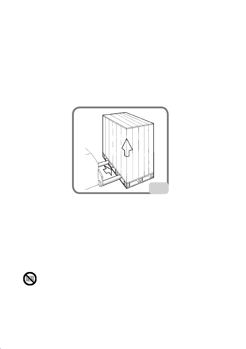
TRANSPORT, STORAGE AND HANDLING.................................................... 74
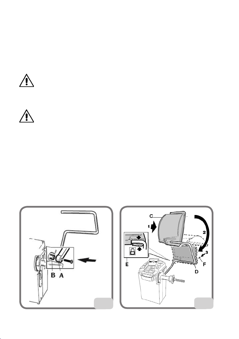
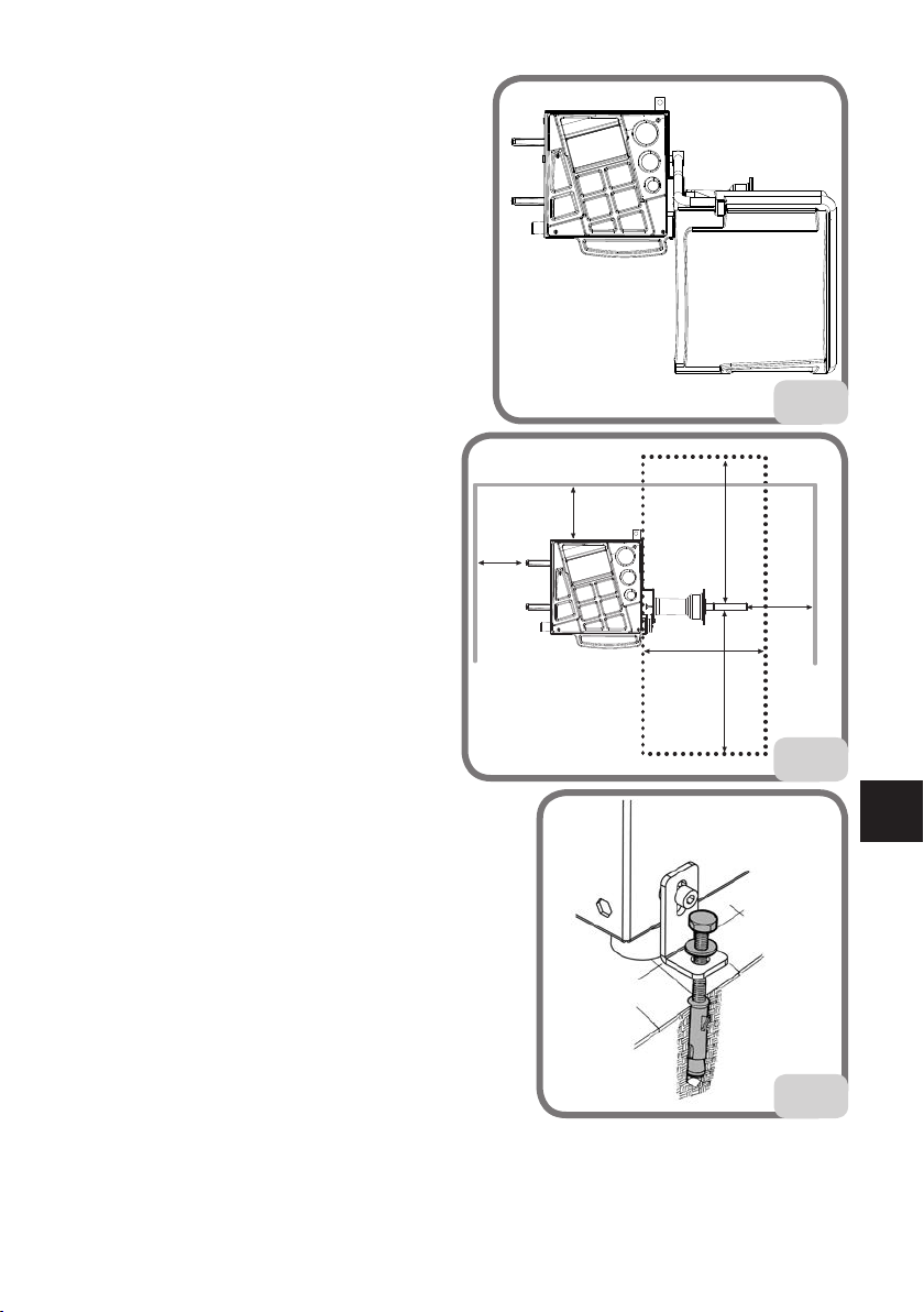
INSTALLATION................................................................................................. 75
ELECTRICAL HOOK-UP................................................................................... 79
COMPRESSED AIR HOOK-UP ........................................................................ 80
SAFETY REGULATIONS................................................................................... 81
MAIN FEATURES.............................................................................................. 82
TECHNICAL DATA............................................................................................ 83
STANDARD EQUIPMENT................................................................................ 86
OPTIONAL ACCESSORIES .............................................................................. 86
GENERAL CONDITIONS OF USE................................................................... 86
DISPLAY PANEL ............................................................................................... 87
DISPLAY PANEL - STATUS ICON.................................................................... 88
DISPLAY PANEL - CONTROL KEYPAD .......................................................... 89
1. SWITCHING ON THE MACHINE............................................................... 90
2. BALANCING PROGRAMME SELECTION................................................. 90
3. ENTERING WHEEL DIMENSIONS
(ALU1P AND ALU2P PROGRAMMES EXCLUDED)................................. 92
4. ENTERING WHEEL DIMENSIONS IN BALANCING PROGRAMMES
ALU1P OR ALU2P........................................................................................ 98
5. ENTERING DIMENSIONS IN THE MOTORCYCLE PROGRAMMES.... 101
6. WHEEL SPIN ............................................................................................. 101
7. UNBALANCE DISPLAY WITHOUT ROUNDING-OFF ............................ 102
8. APPLYING BALANCING WEIGHTS ......................................................... 102
9. APPLYING BALANCING WEIGHTS IN THE ALU1P
OR ALU2P PROGRAMMES ...................................................................... 104
10.PROGRAM FOR POSITIONING THE WEIGHTS BEHIND
THE SPOKES “HIDDEN WEIGHT”
(ONLY WITH ALU 1P AND ALU 2P PROGRAMMES)............................. 106
11. PROGRAM FOR DIVIDING THE WEIGHT ON EITHER SIDE OF THE
SPOKE “SPLIT WEIGHT” (ONLY WITH MOTORCYCLE PROGRAMMES) 108
12.UNBALANCE OPTIMISATION PROGRAMME “OPT”............................. 109
13.ENABLING THE OTHER OPERATOR ..................................................... 111
14.SPIN COUNTER......................................................................................... 112
15.GENERAL CONFIGURATIONS - SET UP................................................ 112
15.1. SET UP - SELECTING VEHICLE TYPE (CAR-MOTORCYCLE)........... 113
ORIGINAL INSTRUCTIONS
COMIM - Code 4-119438 dated 09/2015.

72 EM 9250 Operator’s manual
15.2. SET UP – SELECTING THE MODE FOR ACQUIRING WHEEL
DIMENSIONS IN BALANCING PROGRAMMES ALU1 AND ALU2.... 114
15.3. SET UP - UNBALANCE UNIT OF MEASURE....................................... 115
15.4. SET UP - UNBALANCE ROUNDING-OFF ........................................... 116
15.5. SET UP - WARNING OPT ...................................................................... 117
15.6. SET UP - RIM DIAMETER DISPLAY UNIT OF MEASUREMENT ....... 117
15.7. SET UP - RIM WIDTH DISPLAY UNIT OF MEASUREMENT.............. 118
15.8. SET UP – ACOUSTIC SIGNAL............................................................... 118
15.9. SET UP - ADHESIVE WEIGHT APPLICATION POSITION
(H3-H6-H12)........................................................................................... 119
15.10. SET UP - LED LIGHT (IF PROVIDED) ............................................... 120
15.11. SET UP - LASER INDICATOR (IF PROVIDED).................................. 121
15.12. AUTOMATIC POSITION SEARCH....................................................... 121
16.UNBALANCE CALIBRATION WITH CALIBRATION WEIGHT................ 122
17.ULTRASONIC WIDTH SENSOR CALIBRATION (IF INSTALLED) ......... 123
18.EXTERNAL MECHANICAL SENSOR CALIBRATION (IF INSTALLED). 125
19.DISPLAY MESSAGES................................................................................ 126
20.OTHER MESSAGES.................................................................................. 128
CORRECT FUNCTION OF BALANCING ACCESSORIES............................. 130
TROUBLESHOOTING .................................................................................... 130
MAINTENANCE.............................................................................................. 132
SCRAPPING..................................................................................................... 132
ENVIRONMENTAL INFORMATION.............................................................. 132
RECOMMENDED FIRE EXTINGUISHING DEVICES .................................. 133
GLOSSARY ...................................................................................................... 134
GENERAL ELECTRICAL INSTALLATION DIAGRAM .................................. 136

EM 9250 Operator’s manual 73
UK
INTRODUCTION
The purpose of this manual is to provide the owner and operator with effective and safe
instructions for the use and maintenance of the wheel balancer.
Follow all of the instructions carefully and your machine will assist you in your work and
give long-lasting and efficient service, in keeping with manufacturer traditions.
The following paragraphs define the levels of danger regarding the machine, associated
with the warning captions found in this manual.
DANGER
Refers to immediate danger with the risk of serious injury or death.
CAUTION
Dangers or unsafe procedures that can cause serious injury or death.
WARNING
Dangers or unsafe procedures that can cause minor injuries or damage to property.
Read these instructions carefully before starting the machine. Keep this manual and all
illustrative material supplied with the machine in a folder near it where it is readily ac-
cessible for consultation by the operators.
The technical documentation supplied is considered an integral part of the machine; in
the event of sale all relative documentation must remain with the machine.
The manual is only to be considered valid for the machine model and serial number
indicated on the data plate.
CAUTION
Adhere to the contents of this manual: The producer declines all liability in the case
of actions not specifically described and authorised in this manual.
NOTE
Someof theillustrations containedin thismanual werederived fromphotos ofprototypes:
the standard production machines may differ in some details.
These instructions are for the attention of personnel with basic mechanical skills. We have
therefore condensed the descriptions of each operation by omitting detailed instructions
regarding, for example, how to loosen or tighten the fixing devices on the machine. Do not
attempt to perform operations unless properly qualified and with suitable experience.
If in need of assistance, call an authorised assistance centre.

74 EM 9250 Operator’s manual
TRANSPORT, STORAGE AND HANDLING
Handling and manoeuvring before installation
The basic wheel balancer packaging consists of 1 wooden crate containing:
- the wheel balancer (Fig.7)
- equipment;
- the wheel guard and corresponding mounting tube (C, Fig.4a - D, Fig. 4a).
Before installation, the wheel balancer must be shipped in its original packaging, making
sure that the machine is maintained in the position indicated on the outer packaging. The
machine can be moved by placing the packaging on a wheeled trolley or inserting the
forks of a fork lift truck in the relative slots in the pallet (Fig. 1).
1
- Packaging dimensions:
Length Depth Height Weight Packaging weight
(mm) (mm) (mm) (kg) (kg)
1150 990 1175 120 (PR version) 30
110 (no PR version)
- The machine must be stored in an environment meeting the following requirements:
• relativehumidityrangingfrom20%to95%;
• temperaturerangingfrom-10°to+60°C.
WARNING
Do not stack more than two packs to avoid damaging them.
After installation, the machine can be moved using the following methods:
- with a crane, using special equipment that holds the machine at the designated lifting
points (Fig. 2);

EM 9250 Operator’s manual 75
UK
- by inserting the forks of a lift truck under the machine so that the centre of the forks
correspond approximately to the centre line of the body (Fig. 3).
2
3
CAUTION
Always unplug the power supply cable from the socket before moving the machine.
CAUTION
Never apply force to the wheel spin shaft when moving the machine.
INSTALLATION
CAUTION
Take the utmost care when unpacking, assembling, lifting and setting up the machine
as indicated below.
Failure to observe these instructions can damage the machine and compromise the
operator's safety.
Removetheoriginalpackagingmaterialsafterpositioningthemasindicated onthepackaging
and keep them intact so the machine can be safely shipped at a later date if necessary.
CAUTION
Choose the place of installation in compliance with local regulations on occupational
safety.
In particular, the machine must only be installed and used in protected environments
where there is no risk of anything dripping onto it.

76 EM 9250 Operator’s manual
IMPORTANT: for the correct and safe operation of the machine, the lighting level in the
place of use should be at least 300 lux.
The floor must be strong enough to support a load equal to the weight of the equipment
plus the maximum load allowed. The support base on the floor and the envisaged fixing
means must also be taken into account.
Environmental operating conditions must comply with the following requirements:
-relativehumidityrangingfrom30%to80%(withoutcondensation);
-temperaturerangingfrom0°to+50°C.
WARNING
For information concerning the technical features, warnings and maintenance instruc-
tions consult the related operator manuals provided with the documentation of the
machine.
CAUTION
The machine must not be operated in potentially explosive atmospheres.
The machine is supplied partially disassembled and is to be assembled according to
the procedures described below.
Installing the wheel guard with the corresponding mounting (Fig. 4)
- Install the bush (A, fig. 4) on the pivot (B, fig. 4). While doing this, ensure that the groove
on the pivot is aligned with the pin in the bush.
- Fasten the tube on the pivot using the M12 screw supplied.
- Insert the metal tube (D, Fig. 4a) into the two plastic guard front holes (C, Fig. 4a).
- Couple the guard to the rear side of the tube by inserting it into the correct position
with snap-in coupling (E, Fig. 4a).
- Secure the wheel guard by tightening the screw provided (F, Fig. 4a).
44a

EM 9250 Operator’s manual 77
UK
Fixing the machine to the
ground (Fig. 6)
The machine is to be fixed to the ground if:
- Itdoesnothavetheaccessorytriangularfoot.
- If it does have the accessory triangular foot
but is going to be used with wheels heavier
than 50Kg. In such a case the triangular foot
will have to be removed in order to fix the
front bracket.
- Undo the three M8x60 hex head screws
fastening the machine to the pallet.
- Remove the plastic washers between the
casingandthethreeLbrackets:these brack-
ets will be used to fasten the machine
to the floor.
- Refit the brackets on the machine in the
original positions, without tightening
the screws.
- Positionthemachineonthegroundinthe
selectedpositionandmakesurethatthe
surrounding spaces correspond to the
minimum values indicated in Fig. 5/5a.
- Tracethepositionfor drillingonthe floor.
- Drillin thetraced positionandthentake
theincluded FischerM8 andinsert them
into the holes that were made.
- Securethemachinetothefloorbyfasten-
ing the L brackets to the Fischer anchor
boltsusingtherelativescrewsandwashers (fig.6).
- Tighten the three fastener screws to the casing.
1000
1000
600
600
30003000
5a
5
6

78 EM 9250 Operator’s manual
Fitting the external mechanical sensor and relative support
(if available)
Refer to the instructions provided with the kit, code 8-21100239 EXTERNAL MEASURING
SENSOR+SUPPORT+INNERCABLE.
Assembly of the ultrasonic sensor and its “optional accessory
supplied on request” support for automatic width measurement
(Only for machines equipped with the RPA programme and wheel
guard)
- Insert the ultrasonic sensor cable inside the slots in the metal pipe (see fig.7) fixing
the cable using the supplied hose clamp
(A, fig.7).
- Fasten the ultrasonic sensor to the guard
pipe with the three supplied M8 screws
(Fig.7a).
- Connect the sensor cable to the connector
on the side of the casing (A, fig.7b).
IMPORTANT: after installing the ultrasonic
sensor, calibrate the sensor as described
in the paragraph “Calibrating ultrasonic
width measuring sensor”.
After installing the machine, move into the
selected location, ensuring that the spaces
surrounding the machine comply with the
minimum dimensions indicated in Fig. 5a.
7
7a 7b

EM 9250 Operator’s manual 79
UK
Main working parts (Fig. 8)
8
(A) automatic diameter and distance measuring arm
(B1) automatic width measuring arm (if present)
(B2) automatic width measuring ultrasonic sensor (optional)
(C) head
(D) display panel
(E) flange holder
(F) weight tray
(G) wheel support shaft
(H) cone holder
(J) wheel guard
(L) wheel-holder shaft locking brake
ELECTRICAL HOOK-UP
On request, the wheel balancer can be set up by the manufacturer to operate with the power
supply available in the place of installation. The set-up data for each machine are given on
the machine data plate and on a special label attached to the power supply connection cable.
CAUTION
Any operations for hooking up to the workshop electrical board must be carried out only by
qualified technicians in compliance with the regulations in force, under the responsibility
and at the charge of the customer.
- The electric hook-up must be performed according to:
• absorbedpowerspecicationsindicatedonthemachinedataplate;
• thedistancebetweenthemachineandtheelectrichook-uppoint,sothatvoltagedrops
underfullloaddonotexceed4%(10%whenstartingup)oftheratedvoltagespecied
on the data plate.

80 EM 9250 Operator’s manual
- The user must:
• taplugthatrespectsthecurrentregulationsontothepowersupplycable;
• connectthemachinetoitsownelectricalconnectionttedwithasuitable30-mAcurrent
sensitive circuit breaker;
• tpower supplyprotectionfusessizedincompliancewithspecicationsinthemain
wiring diagram of this manual;
• providetheworkshopelectricinstallationwithanefcientgroundingcircuit.
- Prevent unauthorised use of the machine, always disconnect the power supply plug when
the machine is not used (switched off) for extended periods of time.
- If the machine is connected directly to the power supply by means of the main electrical
board and without the use of a plug, install a key-operated switch or suitable lock-out device
to restrict machine use exclusively to qualified personnel.
CAUTION
For the machine correct functioning it is vital to have a good ground connection. NEVER
connect the machine ground wire to a gas pipe, water pipe, telephone cable or any other
unsuitable object.
COMPRESSED AIR HOOK-UP
WARNING
The compressed air hook-up may only be performed if the pneumatic ring nut is sup-
plied (optional accessory supplied on request).
CAUTION
All compressed air hook-ups must be carried out by qualified personnel only.
- The hook-up to the workshop compressed air system must ensure a minimum pressure
of 8 bar.
- A universal union is used for connection to the compressed air system. No special or
additional adaptor is needed for connection. A pressure-resistant hose with 6mm inner
diameter and 14mm outer diameter must be fastened to the notched union using the
clamp provided with the machine.

EM 9250 Operator’s manual 81
UK
SAFETY REGULATIONS
CAUTION
Non-compliance with the instructions and danger warnings can cause serious injuries
to the operator or other persons.
Do not operate the machine until you have read and understood all the danger/warn-
ing notices in this manual.
In order to operate the machine correctly, it is necessary to be a qualified and authorised
operator, able to be trained and to know the safety regulations. Operators are expressly
forbidden from using the machine under the influence of alcohol or drugs capable of
affecting physical and mental capacity.
The following conditions are essential:
- the operator must be able to read and understand the contents of this manual;
- have a thorough knowledge of the features and characteristics of the machine;
- keep unauthorised persons well clear of the working area;
- make sure that the machine has been installed in compliance with all relevant standards
and regulations in force;
- make sure that all machine operators are suitably trained, that they are capable of using
the machine correctly and safely and that they are adequately supervised during work;
- do not touch power lines or the inside of electric motors or any other electrical equip-
ment before making sure that they have been powered off;
- read this booklet carefully and learn how to use the machine correctly and safely;
- always keep this user manual in a place where it can be readily consulted and do not
fail to refer to it.
CAUTION
Do not remove or deface the DANGER, WARNING, CAUTION or INSTRUCTION decals.
Replace any missing or illegible decals. If one or more decals have been detached or
damaged, they can be replaced by your nearest manufacturer dealer.
- When using and carrying out maintenance on the machine, observe the unified indus-
trial accident prevention regulations for high voltage industrial equipment and rotating
machinery.
- Any unauthorised modification to the machine releases the manufacturer of all liability
in the event of damage or personal injury resulting from said modification. Specifically,
tampering with or removal of the machine safety devices is a breach of the regulations
relating to Safety at Work.
CAUTION
During work and maintenance operations, always tie back long hair and do not wear
loose clothing, ties, necklaces, wristwatches or any other items that may get caught
up in the moving parts.

82 EM 9250 Operator’s manual
Key to caution and instruction labels
Never use the wheel spin shaft as a lifting point for the machine.
Unplug the power supply plug before performing any maintenance/
repair operations on the machine.
Do not lift up the guard when the wheel is turning.
Please use centring accessories with hole diameter 40 mm.
MAIN FEATURES
- Low balancing speed:
• minimiseswheelspintimes;
• reducesriskduetorotatingparts;
• savesenergy.
- Automatic sensor for distance and diameter measurement.
- Automatic mechanical sensor for width measurement (if present).
- AWD (Auto Width Device) programme for measuring the width using an ultrasonic sensor
(if present).
- AWC” (Auto Width Calculation) programme for enabling the manual insertion of the
width (if present).
- Automatic brake for stopping the wheel at the end of the spin.
- Wheel-holder shaft locking brake.
- STOP button to stop the machine immediately.
- Side flange holders.
- Top tray to take weights of all types.
- Automatic start by lowering the guard.
- Luminous digital display unit double display and 3D graphics.
- Microprocessor processing unit (16 bit).

EM 9250 Operator’s manual 83
UK
-Resolution:1g(1/10oz).
- Wide selection of programmes making the machine easy to use.
- Unbalance value display in grams or ounces.
- Unbalance display rounding-off setting.
- Balancing modes available:
• Standard dynamic on both rim sides
• Alu/AluP seven different routines for alloy rims
• MotorcycleMotorcycle dynamic on both sides for motorcycle rims
• MotorcycleALU dynamic on both sides of alloy motorcycle rims
• Static on a single side.
- “Shift planes” programme (in Alu P) for using multiple five gram weights, i.e.: available
without the need for partial cuts.
- “Hidden Weight” programme (in Alu P) in order to divide the outer side balancing
adhesive weights into two equal weights positioned behind the spokes of the rim.
- “Split Weight” programme (motorcycle programmes) to divide the weight into two
equivalent values to be placed on either side of the spoke.
- “OPT flash” programme for rapid optimisation of operating noise reduction.
- “FSP” (Fast Selection Program) programme for the automatic selection of the balancing
programme.
- General utility programmes:
• calibration
• service
• diagnostics.
- Independent working environments that allow a maximum of two operators to work in
parallel with no need to reset any data.
- RPA: automatic wheel positioning in the position where the balancing weight has to be
applied (if present).
- Possibility to select the position for applying the adhesive weight:
•Vertical plane in the lower part of the wheel (H6) using the LASER line
•Vertical plane in the upper part of the wheel (H12)
•CLIP: using the weight-holder terminal in the ALUP balancing programmes (in all the
other H12 balancing programmes)
- LED light (if present).
- LASER indicator (if present).
TECHNICAL DATA
- Single-phase power supply voltage ................. 100/115±10%,200/230V±10%,50/60Hz
- Rated power................................................................................................................... 100 W
- Rated current ...................................................................1 A at 100-115V, 0.5A at 200-230V
- Balancing speed ....................................................................................................90/130 rpm
- Maximum unbalance value calculated ................................................................ 999 grams
- Average spin time (with 5”x14” wheel).........................................................................7 sec
- Shaft diameter ..............................................................................................................40 mm
- Ambient work temperature....................................................................................5°to40°C

84 EM 9250 Operator’s manual
Machine dimensions (Fig. 9-9a)
• depthwithguardclosedwithouttheautomaticsensorformeasuringwidth...............1036 mm
• depthwithguardclosedwiththeautomaticsensorformeasuringwidth ....................1307 mm
• depthwithguardopen ........................................................................................................1086 mm
• widthwithguard,withoutautomaticwidthmeasurementsensor .................................1293 mm
• widthwithguard,withautomaticwidthmeasurementsensor .......................................1389 mm
• heightwithguardclosed......................................................................................................1392 mm
• heightwithguardopen........................................................................................................1645 mm
• depthwithoutguardwithouttheautomaticsensorformeasuringwidth .......................583 mm
• depthwithoutguard,withautomaticwidthmeasurementsensor...................................861 mm
• widthwithoutguardwithoutautomaticsensorformeasuringwidth.............................1195 mm
• widthwithoutguard,withautomaticwidthmeasurementsensor .................................1389 mm
• heightwithoutguard ............................................................................................................1022 mm
9
9a
1367
1641
1298
1022
583
1154 1013

EM 9250 Operator’s manual 85
UK
Working range
•settablerimwidth...............................................................................................................from 1.5" to 20"
•rimdiametermeasurablewiththesensor(versionwithautomaticsensor)................from 11” to 28”
•settablerimdiameterfrom ...........................................................................................................1" to 35"
•max.wheel/machinedistance ........................................................................................................360 mm
•max.wheelwidth(withguard) .......................................................................................................600 mm
•Max.wheeldiameter(withguard) ...............................................................................................1117 mm
- Max. wheel weight................................................................................................................................... 75 kg
- Machine weight with guard (without accessories) and without the external measuring sensor 193 kg
- Machine weight with guard (without accessories) and with the external measuring sensor ...... 200 kg
- Noise level in operation ...............................................................................................................< 70 dB(A)
1154
1291
1389 9b
9c

86 EM 9250 Operator’s manual
STANDARD ACCESSORIES
The following parts are supplied together with the machine.
Weight pliers
Threaded hub
Calliper for wheel width measurement
Hexagonwrench,size10
Calibration weight
Power cable
Small cone
Medium cone
Large cone
Small wheel fixing cap protection
Spacer cap
Small wheel fixing cap
Quick fastener ring for locking wheel
OPTIONAL ACCESSORIES
Please refer to the relevant accessories catalogue.
GENERAL CONDITIONS OF USE
The equipment is intended for professional use only.
CAUTION
Only one operator at a time can work with the machine.
The wheel balancers described in this manual must be used exclusively to measure the
extent and position of car wheel unbalances, within the limits specified in the Technical
specification section. Furthermore, models equipped with motors must be provided
with a suitable guard, fitted with a safety device, which must be lowered during the spin
operation.
CAUTION
Any use of the machine other than the described use is to be considered as improper
and unreasonable.
WARNING
Do not start the machine without the wheel locking equipment.
CAUTION
Do not use the machine without the guard and do not tamper with the safety device.

EM 9250 Operator’s manual 87
UK
WARNING
Do not clean or wash the wheels mounted on the machine with compressed air or
jets of water.
CAUTION
When working, never use equipment not manufactured by the manufacturer.
CAUTION
Get to know your machine: The best way to prevent accidents and obtain top perfor-
mance from the machine is to ensure that all operators know how the machine works.
Learn the function and location of all the controls.
Carefully check that all controls on the machine are working properly.
To prevent accidents and personal injury, all the equipment must be correctly installed,
correctly operated and correctly serviced.
DISPLAY PANEL

88 EM 9250 Operator’s manual
DISPLAY PANEL - STATUS ICON
STATUS ICON DESCRIPTION
Unbalance
rounding-off
Unbalance rounding-off to 5 grams or 0.25 ounc-
es.
If off, the rounding-off is to 1 gram or 0.10 ounce.
Car environ-
ment
Car environment active, the balancing pro-
grammes are dedicated to wheels for cars and
lightweight transport vehicles.
Motorcycle
environment
Motorcycle environment active, the balanc-
ing programmes are dedicated to motorcycle
wheels.
Hidden weight:
Hidden Weight function active (with car mode
active) or Spilt Weight function (with motorcycle
mode active).
Operator 2 Operator 2 active. If off, the active operator is 1.
Optimisation Unbalance optimisation function active (OPT).
Unbalance cali-
bration Unbalance calibration function active.
Not available Not available.

EM 9250 Operator’s manual 89
UK
DISPLAY PANEL - CONTROL KEYPAD
KEY DESCRIPTION
1Wheel dimen-
sions
- Press this key to manually enter the wheel dimen-
sions in the case of an automatic measurement
system malfunction or for versions with a manual
internal sensor.
2End / Esc
Multifunction key
1. In balancing mode, press this key to temporar-
ily display the value rounded to the gram or
1/10 of ounce.
Note: for ALU1P and ALU2P balancing pro-
grams with shift plane, this key is not enabled.
2. In a menu or in a program, press this key to exit.
3
Internal weight
selection/De-
crease
Multifunction key
1. In balancing mode, press this key to select the
type of weight to use on the inner side of the
wheel.
2. In the menu press this key to navigate.
3. When entering dimensions manually, press this
key to decrease the displayed value.
4Menu / Enter
Multifunction key
1. In balancing mode, press this key to access the
wheel balancer menu.
2. In a menu or in a program, press this key to
change the viewed option.
5
Outer weight
selection/In-
crease
Multifunction key
1. In balancing mode, press this key to select the
type of weight to use on the outer side of the
wheel.
2. In the menu press this key to navigate.
3. When entering dimensions manually, press this
key to increase the displayed value.
6Start
- Press this key to perform a spin with the wheel
guard lowered.
- Searches for another side (with RPA active and
wheel guard open).
7Stop - Press this key to stop the spin.
Table of contents
Other Corghi Wheel Balancer manuals
Popular Wheel Balancer manuals by other brands

Hofmann
Hofmann megaspin 300 Operating instructions manual

Atlas
Atlas TC255 Installation & operation manual

Phoenix
Phoenix PWB-1535A Installation and operation manual

Ranger Products
Ranger Products DST-1500 Installation and operation manual

Butler
Butler SPEEDLINER 8050WS instruction manual

HENNESSY INDUSTRIES
HENNESSY INDUSTRIES Coats 885 Safety Instructions, Set Up Instructions, Operation Instructions, Maintenance Instructions