4 Function
4.1 Overcurrent protection
¡Over Current Protection (OCP) is built in and works at 105% of
the rated current or higher. However, use in an over current situa-
tion must be avoided whenever possible. The output voltage of the
power module will recover automatically if the fault causing over
current is corrected.
When the output voltage drops after OCP works, the power mod-
ule enters a ”hiccup mode” where it repeatedly turns on and off at
a certain frequency.
4.2 Overvoltage protection
¡Over Voltage Protection (OVP) is built in. When OVP works, out-
put voltage can be recovered by shutting down DC input for at
least one second or by turning off the remote control switch for
one second without shutting down the DC input. The recovery
time varies according to input voltage and input capacitance.
Remarks:
Note that devices inside the power module may fail when a volt-
age greater than the rated output voltage is applied from an exter-
nal power supply to the output terminal of the power module. This
could happen in in-coming inspections that include OVP function
test or when voltage is applied from the load circuit. OVP can be
tested by using the TRM terminal. Consult us for details.
4.3 Thermal protection
¡Over Temperature Protection (OTP) is built in. If the base plate
temperature exceeds 100C, OTP will work, causing the output
voltage to drop. Output voltage can be recovered by shutting
down DC input for at least one second or by turning RC off for one
second without shutting down the DC input.
¿DHS200, DHS250
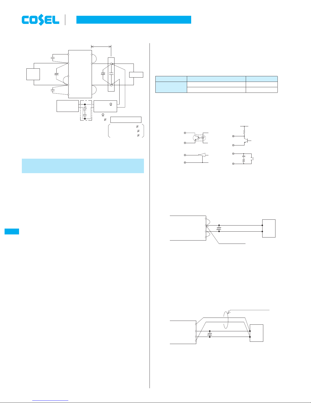
4.5 Remote sensing
(1) When Remote Sensing is Not Used
¡When remote sensing is not used, make sure +VOUT and +S are
shorted, and that -VOUT and -S are shorted as well.
¡Keep the patterns between +S and +VOUT and between -S and
-VOUT as short as possible. Avoid a looping pattern. If noise en-
ters the loop, the operation of the power module will become un-
stable.
(2) When Remote Sensing is Used
¡Using remote sensing with long wires may cause output voltage to
become unstable. Consult us if long sensing wiring is necessary.
¡Sensing patterns or wires should be as short as possible. If wires
are used, use either twisted-pair or shielded wires.
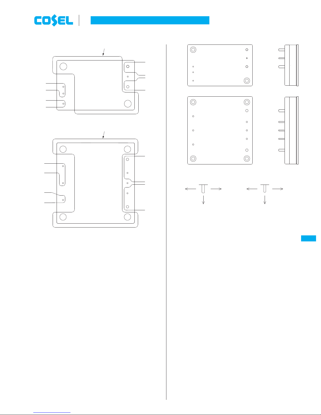
+S
+VOUT
-S
-VOUT
+Co
Short at pin root
Load
+S
Co
-S
+VOUT
-VOUT
+
Wire as close as possible
Load
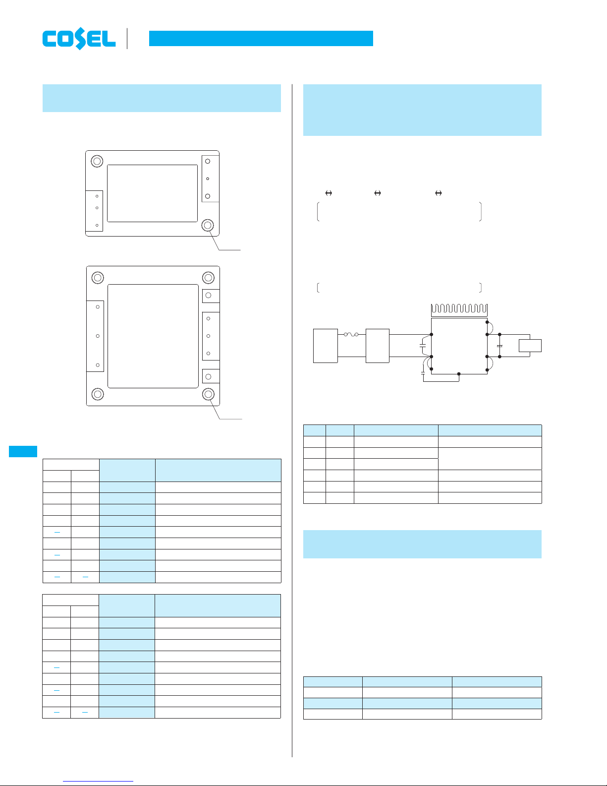
4.4 Remote ON/OFF
¡The remote ON/OFF function is incorporated in the input circuit
and operated with RC and -VIN.
ON/OFF logic Between RC and -VIN Output voltage
Negative L level(0 - 1.2V) or short ON
H level(3.5 - 7.0V) or open OFF
¡When RC is at low level, a current of 0.5mA typ will flow out.
When Vcc is used, keep it within the following rage:
3.5 [VCC [7V.
When remote ON/OFF is not used, short RC and -VIN.
C
1:3.3 - 15V 10
F
24 - 28V 4.7
F
48V 2.2
F
FG
Cin
2200pF
100mm
+VIN
-VIN
FG
+VOUT
-VOUT
-S
+S
C
1
Co
+
+
RC
2200pF
Measuring board
Load
DC
input
Oscilloscope
BW:100MHz
1.5m 50
Coaxial Cable
R=50
C=0.01 F
R
C
+S, -S : DHS200/250
DC-DC Converters Bus Converter.Power Module Type
Instruction Manual
DHS-18
DHS
Fig. 4.1 RC Connection Example
Table 4.1 Remote ON/OFF Specifications
Transistor
IC Relay
Vcc
Opto coupler
RC
-VIN
RC
-VIN
RC
-VIN
RC
-VIN
Fig. 4.2 When Remote Sensing is Not Used (DHS200/250)
Fig. 4.3 When Remote Sensing is Used (DHS200/250)
DHS200
DHS250
DHS200
DHS250
Fig.3.5 Method of Measuring Output Ripple and Ripple Noise
medhs1.inddDHS-18medhs1inddDHS-182015/06/1911:08:052015/06/1911:08:05