Cosel MG15 User manual

2.1 Wiring input pin
2.2 Wiring output pin
1.1 Input Voltage Range
1.2 Overcurrent Protection
1.3 Overvoltage Protection
1.4 Isolation
1.5 Output Voltage Adjustment Range
1.6 Remote ON/OFF
1.7 Thermal protection (MG40 / MG80)
1 Function MG-81
3.1 Series Operation
3.2 Redundancy Operation
7.1 MG15 / MGF15
7.2 MG30 / MGF30
7.3 MGF40
7.4 MGF80
11.1
MG15/MGF15 Lifetime expectancy depends on stress by temperature difference
11.2
MG30/MGF30 Lifetime expectancy depends on stress by temperature difference
11.3
MGF40 Lifetime expectancy depends on stress by temperature difference
11.4
MGF80 Lifetime expectancy depends on stress by temperature difference
5 Cleaning MG-84
6Safety Standards MG-84
7 Temperature Measuring Point MG-84
8 Peak Current (Pulse Load) MG-85
9 Using DC-DC Converters MG-86
10 Note to use ±5V output MG-87
4 Input Voltage/Current Range MG-84
MG-83
MG-83
MG-84
MG-84
MG-85
MG-85
MG-87
MG-87
MG-88
MG-88
2 Wiring to Input/Output Pin MG-82
MG-82
MG-83
3 Series/Redundancy Operation MG-83
11 Lifetime expectancy depends on stress
by temperature difference MG-87
MG-81
MG-81
MG-81
MG-81
MG-81
MG-81
MG-82
DC-DC Converters PCB Mount Type
Instruction Manual
MG15, MG30, MG40, MG80
MG-80
October 21, 2020

1Function
1.1 Input Voltage Range
¡If output voltage value doesn’t fall within specications, a unit may
not operate in accordance with specications and/or fail.
1.2 Overcurrent Protection
¡Overcurrent Operation
An overcurrent protection circuit is built-in and activated over
105% of the rated current or above. It prevents the unit from short
circuit and overcurrent. The output voltage of the power supply
will recover automatically if the fault causing over current is cor-
rected.
When the output voltage drops after OCP works, the power supply
enters a “hiccup mode” where it repeatedly turns on and off at a
certain frequency.
1.3 Overvoltage Protection (Excluding MG15)
¡Over Voltage Protection (OVP) is built in. When OVP works, out-
put voltage can be recovered by shutting down DC input for at
least one second or by turning off the remote control switch for
one second without shutting down the DC input. The recovery
time varies according to input voltage and input capacitance.
Remarks :
Note that devices inside the power supply may fail when a voltage
greater than the rated output voltage is applied from an external
power supply to the output terminal of the power supply. This
could happen in in-coming inspections that include OVP function
test or when voltage is applied from the load circuit.
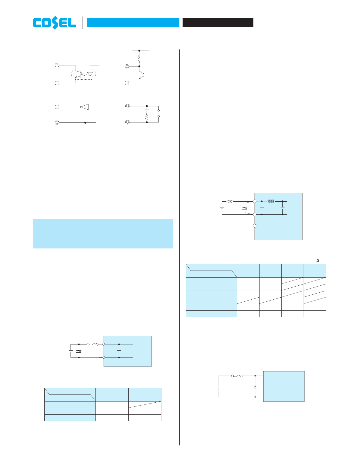
1.4 Isolation
¡When you run a Hi-Pot test as receiving inspection, gradually
increase the voltage to start. When you shut down, decrease the
voltage gradually by using a dial. Please avoid a Hi-Pot tester with
a timer because, when the timer is turned ON or OFF, it may gen-
erate a voltage a few times higher than the applied voltage.
¡
Please note that if foreign matter such as flux during soldering
adheres to the vicinity of the case, the withstand voltage and iso-
latiion resistance may decrease.
1.5
Output Voltage Adjustment Range(MGS/MGFS Only)
¡The output voltage is adjustable through an external potentiom-
eter. Adjust only within the range of ±10% of the rated voltage.
¡To increase the output voltage, turn the potentiometer so that the
resistance value between 2 and 3 becomes small.
¡Please use a wire as short as possible to connect to the potenti-
ometer and connect it from the pin on the power supply side. Tem-
perature coefcient deteriorates when some types of resistors and
potentiometers are used. Please use the following types.
Resistor............
Potentiometer...
¡If output voltage adjustment is not required, open the TRM pin.
¡Output voltage adjustment may increase to overvoltage protection
activation range based on determined external resister values.
Resistor
R2
External
External VR
Resistor
R1
External
Output
TRM
-Vout
+Vout
3
1
2Load
Fig.1.1 Connecting External Devices
Table 1.1 List of External Devices
Item # Output Voltage
Constant of External Device [W]
(Adjustable within ±10%)
VR R1 R2
1 3.3V 1k 100 100
2 5V 1k 100 270
3 12V 5k 10k 1.5k
4 15V 5k 10k 1k
5 ±5V
6 ±12V
7 ±15V
1.6 Remote ON/ OFF
¡The remote ON/OFF function is incorporated in the input circuit
and operated with RC and -Vin. If positive logic control is re-
quired, order the power supply with “-R” option.
Table 1.2 Remote ON/OFF Specications (MG15/MG30)
Model ON/OFF
logic Between RC and -Vin Output
Voltage
Standard
Negative
Llebel (0 - 1.2V) or short ON
Hlebel (3 - 12V) or open OFF
Option-R
Positive
Llebel (0 - 1.2V) or short OFF
Hlebel (3 - 12V) or open ON
Table 1.3 Remote ON/OFF Specications (MG40/MG80)
Model ON/OFF
logic Between RC and -Vin Output
Voltage
MGFO
O05O
Standard Negative
L lebel (0 - 0.4V) or short ON
Hlebel (3 - 12V) or open OFF
Option-R Positive
Llebel (0 - 0.4V) or short OFF
Hlebel (3 - 12V) or open ON
MGFO
O24O/
MGFO
O48O
Standard Negative
Llebel (0 - 0.8V) or short ON
Hlebel (3 - 12V) or open OFF
Option-R Positive
Llebel (0 - 0.8V) or short OFF
Hlebel (3 - 12V) or open ON
¡When RC is at low level, a current of 0.5mA typ will follow out.
(MG15/MG30)
¡When RC is at low level, a current of 0.05mA typ will follow out.
(MG40/MG80)
¡When remote ON/OFF is not used, short RC and -Vin.
Metal Film Type, Temperature Coefficient of
±100ppm/Cor below
Cermet Type, Temperature Coefficient of
±300ppm/Cor below
DC-DC Converters PCB Mount Type
MG15, MG30, MG40, MG80 Instruction Manual
MG-81 October 21, 2020

Vcc
IC Relay
Transistor
Opto coupler
RC
-Vin
RC
-Vin
RC
-Vin
RC
-Vin
Fig.1.2 RC Connection Example
1.7 Thermal protection (MG40/MG80)
¡When the power supply temperature is kept above the values
determined by the derating curve, the thermal protection will be
activated and simultaneously shut down the output.
In this case, the unit should be cool down, and then recovery from
thermal protection is accomplished by cycling the DC input power
off for at least 1 second, or toggling Remote ON/OFF signal.
2 Wiring to Input/Output
Pin
2.1 Wiring input pin
(1) External fuse
¿ MG15, MG30
¡Fuse is built-in on input side.
¿ MG40, MG80
¡Fuse is not built-in on input side. In order to protect the unit, install
the normal-blow type fuse on input side.
¡When the input voltage from a front end unit is supplied to multiple
units, install the normal-blow type fuse in each unit.
Ci
Fuse
-Vin
+Vin
Input
Fig.2.1 Connecting Example of an External Capacitor to the Input Side
Table 2.1 Recommended fuse (normal-blow type)
Model MG40 MG80
Input Voltage[V]
5-12 (MGF) 15A
12-24 (MGF) 10A 15A
24-48 (MGF) 5A 10A
(2) External capacitor on the input side
¡MG series has Pi-shaped lter internally.
You can add a capacitor Ci near the input pin termilal and reduce
reected input noise from the converter. Please connect the ca-
pacitor as needed.
¡When you use a capacitor Ci, please use the one with high fre-
quency and good temperature characteristics.
¡If the power supply is to be turned ON/OFF directly with a switch,
inductance from the input line will induce a surge voltage several
times that of the input voltage and it may damage the power supply.
Make sure that the surge is absorbed, for example, by connecting
an electrolytic capacitor between the input pins.
¡If an external lter containing L (inductance) is added to the input
line or a wire from the input source to the MG series is long, not
only the reected input noise becomes large, but also the output
of the converter may become unstable. In such case, connecting
Ci to the input pin is recommended.
¡If you use an aluminum electrolytic capacitor, please pay attention
to the ripple current rating.
Ci
L
-Vin
+Vin
Input
Fig.2.2 Connecting an External Capacitor to the Input Side
Table 2.2 Recommended Capacitance of an External Capacitor on the Input Side [ F]
Model MG15 MG30 MG40 MG80
Input Voltage[V]
12 220 220
24 100 100
48 47 47
5-12 (MGF) 220
12-24 (MGF) 100 100 100 100
24-48 (MGF) 47 47 47 47
*Please adjust the capacitance in accordance with a degree of the
effect you want to achieve.
¡If a reverse polarity voltage is applied to the input pin, the power
supply will fail.
If there is a possibility that a reverse polarity voltage is applied,
connect a protection circuit externally as described below.
Fuse
Input
+Vin
-Vin
Schottky Barrier
Diode
Fig.2.3 Connecting a Reverse Voltage Protection Circuit
MG15, MG30, MG40, MG80
DC-DC Converters PCB Mount Type
Instruction Manual
MG-82
October 21, 2020

3 Series/Redundancy
Operation
3.1 Series Operation
¡You can use the power supplies in series operation by wiring as
shown below. In the case of (a) below, the output current should
be lower than the rated current for each power supply with the
lowest rated current among power supplies that are serially con-
nected. Please make sure that no current exceeding the rated
current ows into a power supply.
(a)
Power
Supply
Power
Supply
+
-
-
+
Load
(b)
Power
Supply
Power
Supply
+
-
-
+
LoadLoad
Fig.3.1 Series Operation
3.2 Redundancy Operation
¡You can use the power supplies in redundancy operation by wiring
as shown below.
Power
Supply
Power
Supply
I2
I
1
I
3
-
+
+
-
Load
Fig.3.2 Redundancy Operation
¡Even a slight difference in output voltage can affect the balance
between the values of I1and I2.
Please make sure that the value of I3does not exceed the rated
current for each power supply.
I3 [Rated Current Value
2.2 Wiring output pin
¡If you want to further reduce the output ripple noise, connect an
electrolytic capacitor or a ceramic capacitor Co to the output pin
as shown below.
Co
Co
Co
COM
Load
Load
Load
+Vout
-Vout
-Vout
+Vout
MGS/MGFS MGW/MGFW
Fig.2.4 Connecting Example of an External Capacitor to the Output Side
Table 2.3 Recommended Capacitance of External Capacitor on the Output Side [ F]
Model MG15 MG30 MG40 MG80
Output Voltage[V]
3.3 470 470 470 470
5 470 470 470 470
12 150 150 150 150
15 100 100 100 100
±5 330 330
±12 100 100 100 100
±15 47 47 47 47
*If you use a ceramic capacitor, keep the capacitance within the
rage between about 0.1 to 22 F.
*Please adjust the capacitance in light of the effect you want to
achieve.
*If you need to use an unproven external capacitor which capaci-
tance moreover the range provided in Table 2.3, please contact us
for the assistance.
¡If the distance between the output and the load is long and there-
fore the noise is generated on the load side, connect a capacitor
externally to the load as shown below.
Load
Input
+Vin
-Vin
+Vout
-Vout
Fig.2.5 Connecting Example
DC-DC Converters PCB Mount Type
MG15, MG30, MG40, MG80 Instruction Manual
MG-83 October 21, 2020

4 Input Voltage/
Current Range
¡If you use a non-regulated power source for input, please check
and make sure that its voltage uctuation range and ripple voltage
do not exceed the input voltage range shown in specications.
¡Please select an input power source with enough capacity, taking
into consideration of the start-up current (Ip), which ows when a
DC-DC converter starts up.
Ip
Input Current [A]
Input Voltage [V]
Input Voltage Range
Fig.4.1 Input Current Characteristics
5 Cleaning
¡If you need to clean the unit, please clean it under the following
conditions.
Cleaning Method: lmmersion, Ultrasonic or Vapor Cleaning
Cleaning agent: IPA (Solvent type)
Cleaning Time: Within total 2 minutes for lmmersion, ultrasonic
and vapor cleaning
¡Do not apply pressure to the lead and name plate with a brush or
scratch it during the cleaning.
¡Please dry the unit sufciently after cleaning.
¡If you do ultrasonic cleaning, please keep the ultrasonic output at
15W/ or below.
6 Safety Standards
¡To apply for a safety standard approval using the power supply,
please meet the following conditions. Please contact us for de-
tails.
¿Please use the unit as a component of an end device.
¿The area between the input and the output of the unit is isolated
functionally. Depending upon the input voltage, basic insulation,
dual insulation or enhanced insulation may be needed. In such
case, please take care of it within the structure of your end-device.
Please contact us for details.
7 Temperature
Measuring Point
7.1 MG15 / MGF15
¡Please have sufcient ventilation to keep the temperature of point
A in Fig.7.1 at 105Cor below.
Please also make sure that the ambient temperature does not ex-
ceed 85C.
Point A (Center of the Case)
Fig.7.1 Temperature Measuring Point on the case (Top View)
7.2 MG30 / MGF30
¡In case of forced air cooling, please have sufcient ventilation to
keep the temperature of point A in Fig.7.2 at 110Cor below.
Please also make sure that the ambient temperature does not ex-
ceed 85C.
Point A (Center of the Case)
Fig.7.2 Temperature Measuring Point on the case (Top View)
MG15, MG30, MG40, MG80
DC-DC Converters PCB Mount Type
Instruction Manual
MG-84
October 21, 2020

8 Peak Current
(Pulse Load)
¡If a load connected to a converter is a pulse load, you can provide
a pulse current by connecting an electrolytic capacitor externally
to the output side.
Iop
C
+Vin
-Vin
+Vout
-Vout
Pulse Load
External Electrolyti
c
Capacitor
Vo
DVo:Fluctuation of
Output Voltage
Is :
Steady-state Curren
t
Iop:Current at Peak
0
0
Iop
Is
D
T
t
W
aveform of Pulse
L
oad Current
W
aveform of
O
utput Voltage
Vo
¡The average output current lav is expressed in the following for-
mula.
(Iop - Is)Xt
T
lav = ls+
¡Required electrolytic capacitor C can be obtained from the follow-
ing formula.
(Iop - Iav)Xt
DVo
C =
¡Depending on the conditions, output may be stopped by the inter-
nal protection circuit.
7.3 MGF40
¡Please have sufcient ventilation to keep the temperature of point
A in Fig 7.3 at Table 7.1 or below.
Please also make sure that the ambient temperature does not ex-
ceed 85C.
Point A (Center of the Case)
Fig.7.3 Temperature Measuring Point on the case (Top View)
Table 7.1 The temperature of pointA
Model point A
MGFO4005O105C
MGFO4024O110C
MGFO4048O110C
7.4 MGF80
¡Please have sufcient ventilation to keep the temperature of point
A in Fig.7.4 at Fig.7.5 or below.
Please also make sure that the ambient temperature does not ex-
ceed 85C.
Point A (Center of the Case)
Fig.7.4 Temperature Measuring Point on the case (Top View)
-40 -20 0 20 40 60 80 120
100
0
50
100
(105)
Temperature of pointA[C]
Load factor [%]
Fig.7.5 The temperature of PointA
DC-DC Converters PCB Mount Type
MG15, MG30, MG40, MG80 Instruction Manual
MG-85 October 21, 2020

9 Using DC-DC
Converters
¡When using AC power source
-Vin
+Vin
-Vout
COM
+Vout
-15V
0
+15V
¡When using a battery-operated device
-15V
0
+15V
-Vin
+Vin
-Vout
COM
+Vout
¡When a oating mechanism is required for the output circuit
-Vout
+Vout
-Vin
+Vin
Load
Floating from
the GND level
¡To draw a reverse polarity output
-Vout -12V
12V
+Vout
-Vin
+Vin
Example MGS151212
¡To provide a negative voltage to -Vin by using +Vin side of the
converter as GND potential (0V)
-Vout 0-48V
+5V+Vout
-Vin
+Vin
Example MGS154805
¡To draw the sum of input voltage and plus output voltage
-Vout 0
+27V
12V
+Vout
-Vin
+Vin
Example MGS151215
*Output current should be the same as the rated output current of
the converter.
*Output current uctuation is the sum of the input voltage uctua-
tion and the output voltage uctuation of the converter.
¡To use a dual output type
*Dual output type is typically used in the following manner.
-Vout
0
+12V
COM
-12V
+Vout
-Vin
+Vin
Example MGW152412
*The unit can be used as a 24V type single output power supply
as follows.
-Vout
0
+24V
COM
+Vout
-Vin
+Vin
Example MGW152412
*Another way to use the unit is described below.
*The sum of +12V and +24V ows to the 0V line. Please make
sure that this value does not exceed the rated output current of
the converter.
-Vout 0
+24V
+12VCOM
+Vout
-Vin
+Vin
Example MGW152412
¡To draw 48V output
-Vin
+Vin
-Vout
COM
+Vout
0
+48V
-Vin
+Vin
-Vout
COM
+Vout
Example MGW152412
MG15, MG30, MG40, MG80
DC-DC Converters PCB Mount Type
Instruction Manual
MG-86
October 21, 2020

Point A (Center of the Case)
Fig.11.2 Temperature measuring point (Top View)
¡The warranty period is basically 10 years, however it depends on
the lifetime expectancy which is shown in Fig.11.1 if it is less than
10 years.
11.2 MG30 / MGF30 Lifetime expectancy depends on
stress by temperature difference
¡Product lifetime expectancy depends on case temperature differ-
ence ( Tc) and number of cycling in a day is shown in Fig.11.3 (It
is calculated based on our accelerated process test result.)
If case temperature changes frequently by changing output load
factor etc., the above the lifetime expectancy design should be
applied as well. And point A which is shown in Fig.11.4 must keep
below 110C.
Rise/fall temperature difference at point A
Tc [C]
Lifetime expectancy [years]
0
5
10
15
30 35 40 45 50 55 60 65 70 75 80 85
1time ON/OFF/1day
2times ON/OFF/1day
3times ON/OFF/1day
4times ON/OFF/1day
5times ON/OFF/1day
Fig.11.3 Lifetime expectancy against rise/fall temperature difference
Point A (Center of the Case)
Fig.11.4 Temperature measuring point (Top View)
¡The warranty period is basically 10 years, however it depends on
the lifetime expectancy which is shown in Fig.11.3 if it is less than
10 years.
10
Note to use ±5V output
-Vout
R
R
COM
+Vout
-Vin
+Vin
LOAD 100%
LOAD 0-5%
Fig.10.1 Example of decreasing the uctuation of output voltage.
¡If an output current is 0% to 5% of the rated current, the output is
inuenced by the other output load condition.
20% output voltage uctuation may occer.
To avoid the uctuation, external bleeding resister is required to
draw sufcient current.
11
Lifetime expectancy depends on
stress by temperature difference
¡Regarding lifetime expectancy design of solder joint, following
contents must be considered.
It must be careful that the soldering joint is stressed by tempera-
ture rise and down which is occurred by self-heating and ambient
temperature change.
The stress is accelerated by thermal-cycling, therefore the tem-
perature difference should be minimized as much as possible if
temperature rise and down is occurred frequently.
11.1 MG15 / MGF15 Lifetime expectancy depends on
stress by temperature difference
¡Product lifetime expectancy depends on case temperature differ-
ence ( Tc) and number of cycling in a day is shown in Fig.11.1 (It
is calculated based on our accelerated process test result.)
If case temperature changes frequently by changing output load
factor etc., the above the lifetime expectancy design should be
applied as well. And point A which is shown in Fig.11.2 must keep
below 105C.
25 30 35 40 45 50 55 60 65 70 75 80
0
5
10
15
Rise/fall temperature difference at point A
Tc [C]
Lifetime expectancy [years]
1time ON/OFF/1day
2times ON/OFF/1day
3times ON/OFF/1day
4times ON/OFF/1day
5times ON/OFF/1day
Fig.11.1 Lifetime expectancy against rise/fall temperature difference
DC-DC Converters PCB Mount Type
MG15, MG30, MG40, MG80 Instruction Manual
MG-87 October 21, 2020

11.3 MGF40 Lifetime expectancy depends on stress by
temperature difference
¡Product lifetime expectancy depends on case temperature differ-
ence ( Tc) and number of cycling in a day is shown in Fig.11.5 (It
is calculated based on our accelerated process test result.)
If case temperature changes frequently by changing output load
factor etc., the above the lifetime expectancy design should be
applied as well. And point A which is shown in Fig.11.6 must keep
below the values determined by the derating curve.
Rise/fall temperature difference at point A
Tc [C]
Lifetime expectancy [years]
0
5
10
15
30 35 40 45 50 55 60 65 70 75 80
85
1time ON/OFF/1day
2times ON/OFF/1day
3times ON/OFF/1day
4times ON/OFF/1day
5times ON/OFF/1day
Fig.11.5 Lifetime expectancy against rise/fall temperature difference
Point A (Center of the Case)
Fig.11.6 Temperature measuring point (Top View)
¡The warranty period is basically 10 years, however it depends on
the lifetime expectancy which is shown in Fig.11.5 if it is less than
10 years.
11.4 MGF80 Lifetime expectancy depends on stress by
temperature difference
¡Product lifetime expectancy depends on case temperature differ-
ence ( Tc) and number of cycling in a day is shown in Fig.11.7 (It
is calculated based on our accelerated process test result.)
If case temperature changes frequently by changing output load
factor etc., the above the lifetime expectancy design should be
applied as well. And point A which is shown in Fig.11.8 must keep
below the values determined by the derating curve.
Rise/fall temperature difference at point A
Tc [C]
Lifetime expectancy [years]
0
5
10
15
30 35 40 45 50 55 60 65 70 75 80
85
1time ON/OFF/1day
2times ON/OFF/1day
3times ON/OFF/1day
4times ON/OFF/1day
5times ON/OFF/1day
Fig.11.7 Lifetime expectancy against rise/fall temperature difference
Point A (Center of the Case)
Fig.11.8 Temperature measuring point (Top View)
¡The warranty period is basically 10 years, however it depends on
the lifetime expectancy which is shown in Fig.11.7 if it is less than
10 years.
MG15, MG30, MG40, MG80
DC-DC Converters PCB Mount Type
Instruction Manual
MG-88
October 21, 2020
This manual suits for next models
3
Table of contents
Other Cosel Media Converter manuals

Cosel
Cosel TUHS Series Instructions for use

Cosel
Cosel ZUS1R5 User manual

Cosel
Cosel RMC15A User manual

Cosel
Cosel CHS60 User manual

Cosel
Cosel MMC8A User manual

Cosel
Cosel CHS series Use and care manual

Cosel
Cosel DBS100A User manual

Cosel
Cosel DHS50A User manual

Cosel
Cosel TUNS50F User manual

Cosel
Cosel SFS152412C User manual