3
Wiring Input/Output Pin
3.1 Wiring input pin
(1) F1 : External fuse
¡Fuse is not built-in on input side. In order to protect the unit, install
the slow-blow type fuse on input side (as shown in Table 3.1).
Table 3.1 Recommended fuse (Slow-blow type)
Model TUNS50F TUNS100F
Rated current 2A 3.15A
(2) C1 : External Capacitor for input side
¡-
tance and ripple current capability are above the values shown in
Table 3.2.
¡Use a safety approved capacitor with 250V ac rated voltage.
¡If C1 is not connected, it may cause the failure of the power sup-
ply or external components.
Table 3.2 Input Capacitor C1
No. Model Voltage Capacitance Rated ripple
current
1 TUNS50F AC250V 3A or more
2 TUNS100F 3A or more
¡
-
tor CY for low line noise and stable operation of the power supply.
¡The operation of the power supply may be unstable due to the
¡Install a correspondence filter, if it is required to meet a noise
standard or if the surge voltage may be applied to the unit.
¡Install a primary decoupling capacitor CY, with more than 470pF,
near the input pins (within 50mm from the pins).
¡When the total capacitance of the primary decoupling capacitor is
be met by the Hi-Pot test between input and output. A capacitor
should be installed between output and FG.
(4) TH1 : Inrush current limiting thermistor
¡It has a possibility that internal components fail by inrush current,
so please use power thermistor or inrush current limiting circuit to
keep input current below 60A.
¡If you use power thermistor and turn the power ON/OFF repeat-
edly within a short period of time, please have enough intervals
so that a power supply cools down before being turned on. And
appropriate intervals should be set even if inrush current limiting
circuit except power thermistor is used.
¡The output voltage may become unstable at low temperature due
to the ESR of power thermistor. In this case, increase the capaci-
tance of Cbc more than recommended value or connect same
capacitors in parallel. Please evaluate before use.
3.2 Wiring output pin
(1) Co : Output capacitor
¡Install an external capacitor Co between +VOUT and -VOUT pins
for stable operation of the power supply (Fig.2.1).
Recommended capacitance of Co is shown in Table 3.3.
¡Select the high frequency type capacitor. Output ripple and start-
the wiring impedance.
¡Install a capacitor Co near the output pins (within 50mm from the
pins).
¡When the power supply is used under 0Cambient temperature,
output ripple voltage increases. In this case, connect 3 capacitors
Co in parallel connection.
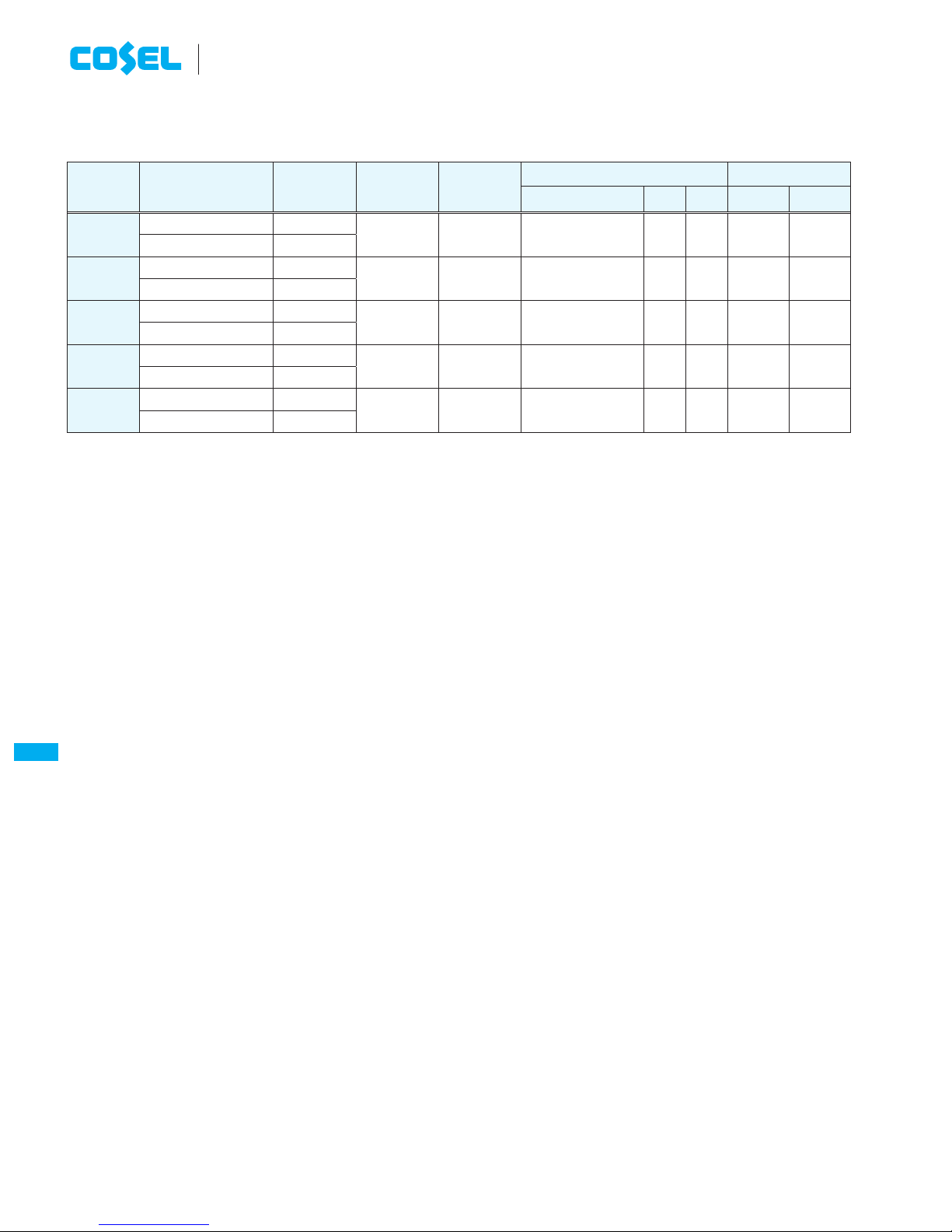
Model Temperature of base plate
Tc=0 to +100CTc=-40 to +100C
Output voltage
(V) TUNS50F TUNS100F TUNS50F TUNS100F
5 2200 2200 2200×3 2200×3
12 470 470 470×3 470×3
24 220 220 220×3 220×3
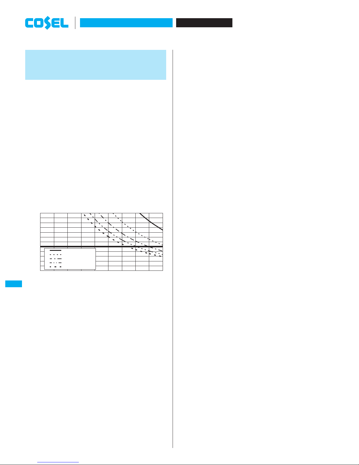
introduced in Fig.3.1.
C4 :
5V,12V 10mF
24V 4 .7mF
FG
+
F1 TH1
FG FG
CY
C1
+BC -BC
Cbc
AC IN
AC1
AC2
+VOUT
-VOUT
-S
+S
TUNS50F
TUNS100F
C2
Load
C4
R
C
+
Co
50mm
Oscilloscope
BW:100MHz
1.5m
50W
Coaxial
Cable R=50W
C=0.01mF
Noise
filter
+S, -S : TUNS100F
Fig.3.1 Method of Measuring Output Ripple and Ripple Noise
3.3 Wiring +BC/-BC pins
(1) Cbc : Smoothing capacitor for boost voltage
¡In order to smooth boost voltage, connect Cbc between +BC and
-BC. Recommended capacitance of Cbc is shown in Table3.4.
¡Note that +BC and -BC terminals have high voltage (DC385V typ).
¡Keep the capacitance within the allowable external capacitance.
¡Select a capacitor of which the boost voltage ripple voltage does
not exceed 30Vp-p.
¡When the power supply is operated under -20C, it may make
the boost voltage unstable due to the characteristic of equivalent
series resistor. Please choose the capacitor which has more than
recommended capacitance.
TUNS50F, TUNS100F
AC-DC Power Supplies Bus Converter.Power Module Type
Instruction Manual
TUNS-15
TUNS