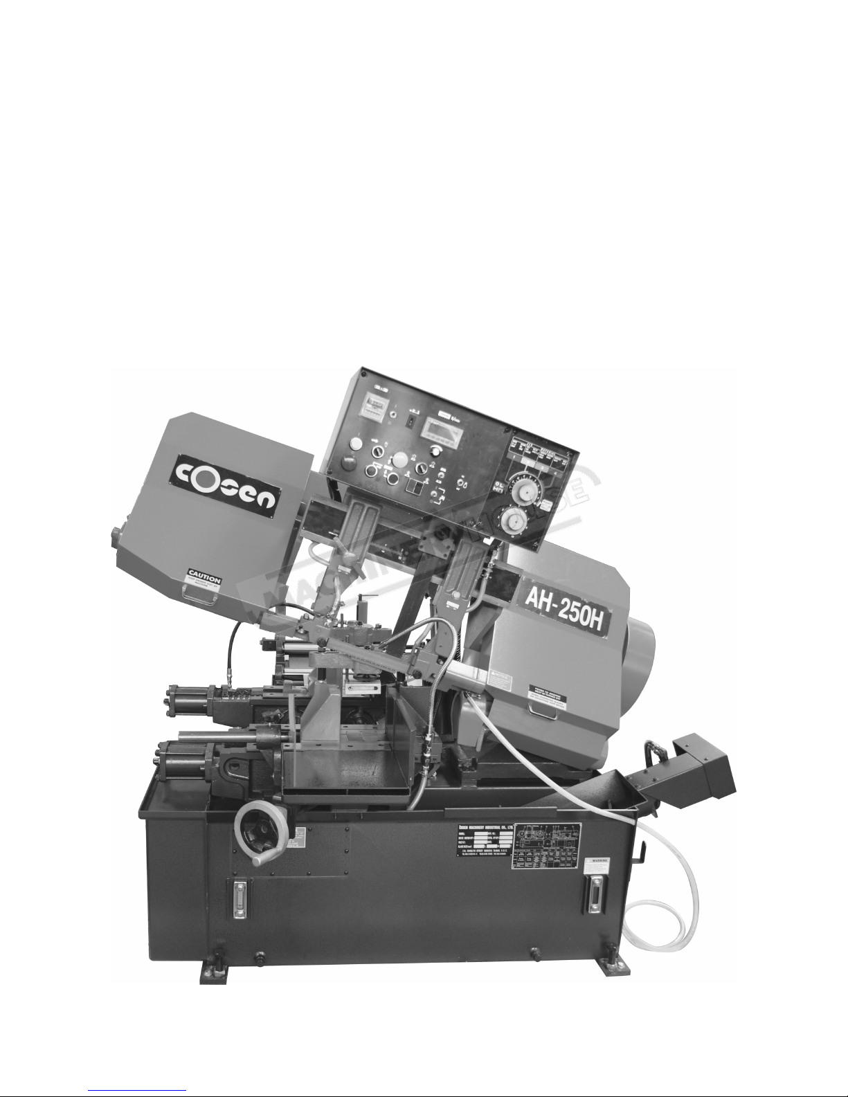
Cosen AH-250H User manual

INSTRUCTION MANUAL
AH-250H
Automatic Hitch Feed Metal Cutting
Band Saw (415V)
280 x 250mm (W x H) Rectangle
B040
Page 1
Instruction Manual for AH-250H (B040)
04/12/2014

Printed in Taiwan
NOTICE: Please read this instruction manual carefully to obtain a
thorough knowledge of installation, operation and maintenance. Please
remember the following: Correctly operate the machine as described in
the manual to prevent accident. Do not operate the machine by guesswork.
We suggest you always keep manual at hand and refer to it whenever you
are not sure of how to perform any procedures for AH-250H.
TECHNICAL ADVICE/ SPARE PARTS
Please contact the COSEN-representative in your local area in case you need any
technical advice or if you want to order spare parts.
Instruction Manual:
AH-250H Automatic Horizontal Bandsaw
Ver. 1—Date : 09/18/1998
Ver. 2 -- Date : 07/01/2003
VER.3 –Date :12/01/2010
©1995 by COSEN CO., LTD./ R&D DIVISION.
110 Ching-Fu Street Hsin-Chu 300, Taiwan, R.O.C.
Tel: 886-3-5332143~5 Fax: 886-3-5348324
No part of this publication may be photocopied or otherwise reproduced without the prior written
permission of COSEN CO., LTD.
Page 2
Instruction Manual for AH-250H (B040)
04/12/2014

Foreword
FROM THE MANUFACTURER
You have just purchased a machine manufactured by the COSEN Machinery
Industrial Co., Ltd. We‘d like to take this chance to express our appreciation to you
for being our valued customer. Any comment from you will help us to design a better
product or provide a better service for you.
The band saw machine will provide low cost cutting accuracy for many years if
the procedures for installation, operation, maintenance and troubleshooting are
followed. However, if there are questions, please contact our agent or our factory for
the nearest service or sales representative.
Enough, already. I hope you find COSEN as incredibly smart as I do. If you
have any suggestions for improvement, please tell us, we will appreciate your help.
“again”
Thank you so much for purchasing COSEN band saw machine.
MikeHuang
President
COSEN Machinery Industrial Co., Ltd.
Page 3
Instruction Manual for AH-250H (B040)
04/12/2014

I
TABLE OF CONTENTS
SECTION
PAGE
1
SAFETY RULES 1-1~5
2
GENERAL INFORMATIONS
2.1 INTRODUCTION 2-1
2.2 EQUIPMENT DESCRIPTION 2-1
2.2.1 SPECIFICATION 2-2
2.2.2 Identification of Main Parts & Terminology 2-3
2.2.3 Emergency Stop Button 2-4
2.2.4 Noise Level 2-4
2.2.5 Safety Devices and Guards 2-5~6
2.2.6 Specification of Electrical Equipment 2-7
2.3 GUIDE TO THE MANUAL 2-8
2.4 DOCUMENTATION 2-8
3
MOVING AND INSTALLATION
3.1 INTRODUCTION 3-1
3.2 MOVING THE MACHINE 3-2
3.3 INSTALLATION OF THE MACHINE 3-3
3.3.1 Safety Precautions 3-4
3.3.2 Initial Inspection 3-4
3.3.3 Space Required 3-4
3.3.4 Unpacking 3-6
3.3.5 Equipment Furnished 3-6
3.3.6 Installation Procedure 3-6
Fixing the Machine on the floor 3-7
Machine Leveling 3-7
Installation of Feed Roller 3-7
Cutting Fluid Supply 3-7
Hydraulic Fluid Supply 3-7
Electrical Connections (Power Requirement) 3-8
Installation Fire Control Devices 3-9
3.4 WORKING CONDITIONS 3-9
3.5 RESHIPMENT PROCEDURE 3-9
Page 4
Instruction Manual for AH-250H (B040)
04/12/2014

II
4
OPERATION INSTRUCTION
4.1 SAFETY PRECAUTIONS 4-1
4.2 PREPARATION FOR USE 4-1
4.3 CONTROLS DESCRIPTION AND OPERATION 4-2
4.3.1 Control panel 4-2
4.3.2 Manual model 4-8
4.4 TEST RUN THE MACHINE 4-15
4.5 HOW TO REPLACE THE SAW BLADE 4-16
4.6 HOW TO LOAD THE WORKPIECE 4-18
4.7 PROCEDURES TO STOP AN OPERATING PROCESS 4-19
4.8 PROHIBITED MEASURES ON THE MACHINE 4-20
5
ELECTRICAL SYSTEM
5.1 INTRODUCTION 5-1
5.2 ELECTRICAL COMPONENTS LAYOUT 5-1
5.3 ELECTRICAL CIRCUIT DIAGRAMS 5-2
6
HYDRAULIC SYSTEM
6.1 INTRODUCTION 6-1
7 BAND SAW CUTTING A PRACTICAL GUIDE
7.1 INTRODUCTION 7-1
7.2 BAND SAW BLADE SELECTION 7-1~3
7.3 Some Sawing Practices 7-4
7.3.1 Selection of Saw Pitch 7-4
7.3.2 Material Size and Saw Pitch 7-4
8
MAINTENANCE & SERVICE
8.1 INTRODUCTION 8-1
8.2 BASIC MAINTENANCE 8-1
8.3 MAINTENANCE SCHEDULE 8-1
Before beginning of work each day 8-2
After ending work each day 8-2
Every monthly maintenance 8-2
Every six months maintenance 8-3
8.4 STORAGE CONDITION OF THE MACHINE 8-3
8.5 TERMINATING THE USE OF THE MACHINE 8-4
8.6 OIL RECOMMENDATION FOR MAINTENANCE 8-5
9
SYSTEM TROUBLE SHOOTING
9.1 INTRODUCTION 9-1
9.2 PRECAUTION 9-1
9.3 GENERAL TROUBLES AND SOLUTIONS 9-2
9.4 MOTOR TROUBLES AND SOLUTIONS 9-3
9.5 BLADE TROUBLES AND SOLUTIONS 9-4
Page 5
Instruction Manual for AH-250H (B040)
04/12/2014

III
9.6 SAWING PROBLEMS AND SOLUTIONS 9-5
9.7 MINOR TROUBLE SHOOTING 9-6
9.8 THE ADJUSTMENT OF THE FEEDING TABLE 9-6
10
PART LIST
INTRODUCTION 10-1
10.01 BAND SAW FOUNDATION ASS'Y 10-2~3
10.02 VISE MACHINE BODY ASS'Y 10-4~5
10.03 TRANSMISSION MACHINCAL ASS'Y 10-6~7
10.04 POWER UNIT ASS'Y 10-8~9
10.05 GUIDE APROACH ASS'Y 10-10~11
10.06 GUIDE BRACKET ASS'Y 10-12~13
10.07 DRIVE WHEEL ASS'Y 10-14~15
10.08 REDUCER GEARBOX BODY ASS'Y 10-16~17
10.09 ELECTRICAL & HYDRAULIC CONTROL BOX ASS'Y 10-18~19
10.10 WIRE BRUSH ASS'Y 10-20~21
10.11 HEAD CYCLINDER ASS'Y 10-22~23
10.12 FEED EQUIPMENT ASS'Y 10-24~25
10.13 MAINFOLD TAPPET CYCLINDER 10-26~27
10.14 WORK FEED DEVICE 10-28~29
10.15 FEED VISE ASS'Y 10-30~31
10.16 MULTI VISE ASS'Y 10-32~33
10.17 FEED CYCLINDER ASS'Y 10-34~35
10.18 IDLE WHEEL ASS'Y 10-36~37
10.19 BLADE TENSION FACILITY ASS'Y 10-38~39
Page 6
Instruction Manual for AH-250H (B040)
04/12/2014

Section 1
SAFETY RULES
Page 7
Instruction Manual for AH-250H (B040)
04/12/2014

SAFETY RULES
Section 1
1-1
SECTION 1
SAFELY RULES
Never wear gloves loose clothing when operating the machine. They may cause danger if they are
caught in a running machine.
Be sure to confirm that the area around the machine is cleared of people and obstacles every time
before starting the machine or operation.
Page 8
Instruction Manual for AH-250H (B040)
04/12/2014

SAFETY RULES
Section 1
1-2
Use a water-soluble cutting fluid on this machine. Oil-based cutting fluids may emit smoke or catch
fire, depending on the condition of their use.
Never try to adjust the wire brush on the saw blade or remove chips when the saw blade is running.
It is dangerous if hands or clothing are caught by the running blade.
Never cut carbon or any other material that produces and disperses explosive dust on this machine.
Sparks from motors and other machine parts may ignite and explode the air-borne dust. The machine
needs special measures for cutting explosive materials.
Page 9
Instruction Manual for AH-250H (B040)
04/12/2014

SAFETY RULES
Section 1
1-3
Stop the saw blade before you clean the machine. It is dangerous if hands or clothing are caught by
the running blade.
Be sure to prohibit any use of fire in the shop, and install a fire extinguisher or other fire control
device near the machine when cutting titanium, magnesium, or any other material that produces
flammable chips. Never operate the machine unattended when cutting flammable materials.
Use roller tables on forward and backward sides of the machine when cutting the long work. It is
dangerous if the work falls off the machine when the roller tables are not used.
Page 10
Instruction Manual for AH-250H (B040)
04/12/2014

SAFETY RULES
Section 1
1-4
Take preventive measures when cutting thin or short pieces from the work to keep them from falling.
It is dangerous if the cut piece falls.
Never start the saw blade unless it has been confirmed that the work is firmly clamped. If the work is
not securely clamped with the vise, pieces will be forced out of the vise during cutting.
Never touch the running saw blade. It is dangerous if your hands or clothing are caught by the
running blade.
Page 11
Instruction Manual for AH-250H (B040)
04/12/2014

SAFETY RULES
Section 1
1-5
Never step or stand on the roller table. It is dangerous if your foot slips on the rollers and you fall.
Turn off the shop circuit breaker switch before servicing the machine. Then post a sign to inform
people that the machine is under maintenance.
Page 12
Instruction Manual for AH-250H (B040)
04/12/2014

Section 2
GENERAL INFORMATION
Page 13
Instruction Manual for AH-250H (B040)
04/12/2014

GENERAL INFORMATION
Section 2
2-1
SECTION 2
GENERAL INFORMATION
2.1 INTRODUCTION
This automatic band saw is a model more popular than any other model as witnessed in many
countries worldwide. This machine was developed by a group of R&D engineers over a considerable
period of time assuring you of the highest efficiency and performance. This machine can automatically
detect the conditions of material supply, cutting and quality control. Each component was developed
by computer design and analysis. This machine is specifically designed to cut metal material. Your
machine has the following advantages:
•Machinery and each component part can be handled safely.
•Machinery and each component part can be easily moved or operated by the user.
•Machinery and each component part has passed strict testing. (Council Directive on the
approximation of the laws of the Member States relating to Machinery)
This manual contains shipping, handling, unpacking, initial checkout, operation, maintenance
information, etc. It is divided into 10 sections. Each section covers a specific aspect of the machine.
This section contains a general description of the machine and other available documentation. We are
going to introduce this smart machine now.
2.2 EQUIPMENT DESCRIPTION
This automatic band saw machine is designed based on the guidelines of low cost and high
performance. It is designed to cut various kinds of materials with the appropriate saw blade installed.
The specific features of this band saw machine are as follows:
1. Concern for safety. This machine is designed to fully protect the operator from its moving
elements while cutting.
2. When the saw blade is broken, the machine will stop automatically.
3. The machine will stop automatically when out of stock.
4. Dual valve system is designed to achieve optimal cutting performance with the simple
setting of feed rate and perspective cutting pressure for different material.
5. The intended life-span of the machine is counted based on regular daily operation. It is
calculated with the life expectancy of 10 years under normal operating condition and
exact attention to the maintenance schedule.
8 hours
× 5 days ×52 weeks ×10 years =20,800 hours
Page 14
Instruction Manual for AH-250H (B040)
04/12/2014

GENERAL INFORMATION
Section 2
2-2
2.2.1 Specifications Specification of The Machine
MODEL Automatic Band Saw Machine (AH-250H)
250 mm (10")
(W×H) 250×250 mm (10"×10")
MAX. CAPACITY
(W×H) 280×250 mm (11"×10")
60 Hz 27, 40, 54, 68, 80 m/min. (27 ~ 80 m/min)
89, 131, 177, 223, 262 fpm. (89 ~ 262 fpm)
SPEED 50 Hz 23, 34, 45, 57, 67 m/min. (23 ~ 67 m/min)
75, 112, 148, 187, 220 fpm. (75 ~ 220 fpm)
SIZE (W×L× T) 27×3505×0.9 mm
34×3505×0.9 mm (OPTION)
TENSION HYDRAULICAL, (Factory adjusted)
GUIDE CARBIDE, (Interchangeable)
SAW BLADE
CLEANING Steel wire brush with flexible drive shaft driven by main motor.
HYDRAULIC 0.75 kW (1 HP)
SAW BLADE 2.2 kW (3 HP)
MOTOR OUTPUT COOLANT PUMP 0.1 kW (1/8 HP)
HYDRAULIC OIL SYSTEM TANK CAPACITY 20 L (5.0 gal.)
COOLANT CAPACITY 38 L (9.5 gal.)
MODE HYDRAULICAL, Automatic
FEEDING LENGTH Max. 3600 mm (max. 141")
VISE CONTROL METHOD STATIONARY & MOVABLE HYDRAULIC VISE
HEIGHT OF WORK BED 550 mm (21.7")
NET WEIGHT 1400 kgs (3080 lbs)
GROSS WEIGHT 1600 kgs (3520 lbs)
2100×2150×1800 mm (74.5"×84.6"×58")
(The length is 4110 mm with the optional roller table)FLOOR SPACE (L×W×H) (The height is 1350 mm when saw bow is at horizontal position)
SHIPPING SPACE (L×W×H) 2200×2170×2000 mm (76.5"×85.4"×62")
* Design and specifications are subjected to change without notice.
Page 15
Instruction Manual for AH-250H (B040)
04/12/2014

GENERAL INFORMATION
Section 2
2-3
2.2.2 Identification of Main Parts & Terminology
FIG 2-1 The main unit of the machine
2.2.3 Emergency Stop Button
Your machine‘s emergency stop button is designed to be very easy to access. When you
press it, it will stop the machine completely to avoid severe injury when an accident occurs.
You should press it immediately without hesitation in the following cases:
•Any emergency situation that would cause severe injury.
•Any abnormal situation or error, such as fire etc.
The button is going to be locked when you press it. To unlock it, you must pull it. Its
appearance has red color and rubber material for safe operation. We hope you do not press this
button inadvertently or otherwise.
2.2.4 Noise Level
Noise has a major effect on the quality of the environment at the work site. We refer you to
testing data and information as follows:
Page 16
Instruction Manual for AH-250H (B040)
04/12/2014

GENERAL INFORMATION
Section 2
2-4
Excessive exposure to high levels of noise may cause impairment to hearing, but the
vulnerability to hearing loss varies between individuals and must be taken into account
in specifying an allowable limit for noise exposure.
A level of 90 dBA is widely accepted as a criterion for 8 hour/day exposure to steady-
state broad-band noise.
The unprotected ear should not be exposed to noise levels higher than 120 dBA. A
machine‘s noise come from the following:
1. Saw blade during cutting or material feed mechanism
2. Wire brush unit
3. Chip conveyor unit
4. Speed reducer
5. Hydraulic motor/pump
6. Belt transmissions variable speed motors
7. Blade motor
8. Coolant Pump
9. Drive wheel
10. Parts, machine not assembled tightly causing mechanical vibration
When your machine is running, noise will come out. This is a machine-electric interface problem
that may make people feel uncomfortable. Our products pass noise testing under 78 dBA. If your
machine produces an undesirable noise while it is running, you should:
1. Be sure maintenance schedule has been followed exactly.
2. If yes, follow section 10 in this manual for system troubleshooting procedures.
2.2.5 Safety Devices and Guards
This manual show safety related components illustration as following:
FIG 2-2 The machine of top view
Page 17
Instruction Manual for AH-250H (B040)
04/12/2014

GENERAL INFORMATION
Section 2
2-5
FIG 2-3 The machine of front view
Safety moving element:
All the major moving elements on the machine include:
1. Saw head assembly.
2. Saw wheels.
3. Saw blade guide/arm.
4. Saw blade guide roller.
5. Quick approcah mechanism.
6. Wire brush.
7. Chip conveyor.
8. Workpiece clamping vises.
9. Material feed mechanism.
10. Multi vises.
11. Belt transmissions variable speed motors or step pulleys.
Safety related switches:
The safety related switches on the machine will be actuated in operating situations. The
automation detector is a proximity sensor used to detect the motion of the drive saw wheel. Once
the saw blade is broken, the driven wheel will stop running. The sensor will be detecting this
problem and then stop the machine.The power switch controls the main power of the machine.
The emergency stop switch on the control panel is a red button (with rubber material). It is used
for emergency stop at any circumstances.
The saw wheel cover interlock switches located on the two wheel housings are used to
assure that the machine will stop whenever the wheel covers are open. This device is to protect
Page 18
Instruction Manual for AH-250H (B040)
04/12/2014

GENERAL INFORMATION
Section 2
2-6
users from being cut by the running saw blades. The vise clamp switch is to assure firm clamping
of the workpiece. If the workpiece is not clamped properly, the saw blade is not allowed to run.
Among all these safety switches, some of them are used to protect the users and some of
them are used to prevent damage to saw blades, the workpiece and the machine itself, etc. We
have taken every precaution to prevent injury or damage and to provide safe and economical
operation of the machine.
Guard mountings:
The locations of all safety guards on the machine are indicated above. All of these protectors
should always be mounted on the machine whenever the machine is running. Users are not
allowed to move any of these elements under any circumstances except when servicing the
machine. However, even skilled service technicians still have to be very careful when performing
repairs or service on the machine with any of these protectors removed. It is the responsibility of
the user to make sure all these elements is not lost and damaged.
2.2.6 Specification of Electrical Equipment
Electrical equipment is very important to the control system. Your machine a new type
system designed for safety by our engineers. We describe briefly as follows:
GROUND DIAGRAM
PLC
UNIT
CONTROL BOX MOTOR
PE
L3
L2
L1
MOTOR
ELECTRICAL CABINET
MOTOR
CHASSIS BODY
GROUND PLATE 1
GROUND PLATE 2
Transformer
DOOR
EMC PROTECTION
1. Provides spark killers on each AC motor, AC control relay.
a. AC Motor : Spark killers are connected between motor phases.
b. AC control relay : Spark killers are connected between coil of AC control circuit.
Page 19
Instruction Manual for AH-250H (B040)
04/12/2014

GENERAL INFORMATION
Section 2
2-7
S1
K1
AC110V
(
2. Waveform measurement circuit and measured waveform.
3. RC circuit
Element marker have introduced in recent years spike killers (sometimes called arrester)
which are made of mainly zinc oxide with a characteristic of varistor. Comparison of their
characteristics toward surge voltage indicates that the former has a smooth attenuation curve
with the crest value of a steep surge voltage being less than 4.5 times of the rated voltage. Noise
entering a signal line due to electromagnetic induction is considered due to the magnitude of
noise change rate rather than due to the noise crest value of the noise generating source. The
attenuation waveform of the RC is therefore less unlikely than the pulse waveform of the
arrester to cause electromagnetic induction. The RC compound element is thus considered better
in noise elimination.
Due to the reasons mentioned above, mount a RC compound element on each of AC motor,
AC solenoid and AC control relay.
2.3 GUIDE TO THE MANUAL
SECTION 1, 2, 3, -------10,
APPENDIX.
The instruction manual is divided into ten sections. Each section contains important information
on how to operate the machine properly. Some of the safety precautions are described at the beginning
of each section. Please read and understand the manual before operating the machine. For other
technical information, please check with the dealer or the manufacturer for further detail.
2.4 DOCUMENTATION
Other than this manual, the manufacturer also provided other related technical documents along
with the machine. Please read through them should there be a need.
Page 20
Instruction Manual for AH-250H (B040)
04/12/2014
Table of contents
Other Cosen Saw manuals

Cosen
Cosen SH-3026L User manual

Cosen
Cosen MH-1016JA User manual

Cosen
Cosen G320 User manual

Cosen
Cosen MH-350DM User manual

Cosen
Cosen SH-1300LDM User manual

Cosen
Cosen SVT-6070H User manual

Cosen
Cosen SH-710LDM User manual

Cosen
Cosen MT-105 User manual

Cosen
Cosen V2230NC User manual

Cosen
Cosen SH-330ER User manual