INSTALLING FURNACE- 9 TO 15" WALLS (CDV1 T.,,-,,3/ tnvz3_Dr Forg"
to 15" wall use Vent Kit No. VK1525/9-15-B. Do not attempt to lengthen the exhaust tube, air intake tube, or wall thimble
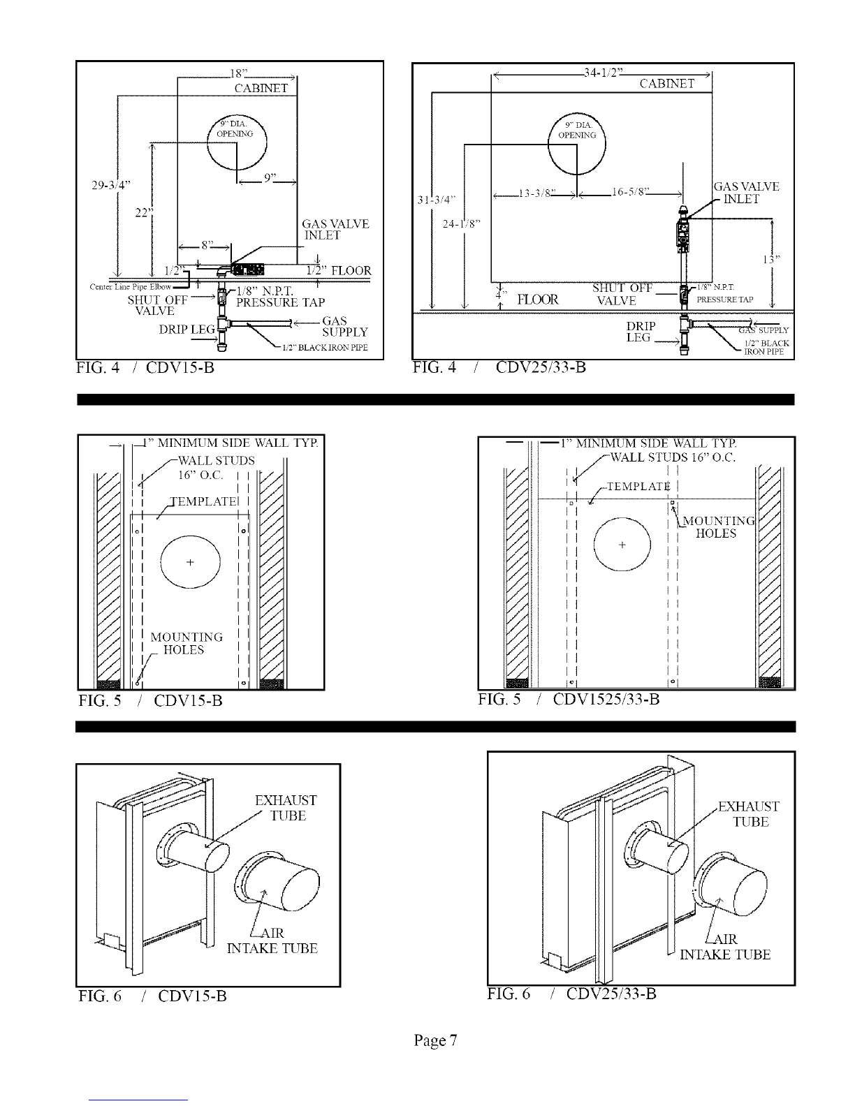
extension provided with furnace or the VK1525/9-15-B Vent Kit. Disconnect the air intake tube, and the exhaust tube fiom the
back of the furnace and discard. See Figure 6. Replace with exhaust tube and air intake tube from Kit No. VK1525/9-15-B.
Discard the 5" telescoping wall thimble extension that surrounds the wall thimble assembly. Center the wall thimble assembly in
the 9" opening and attach to inside wall using eight (8) screws. Install furnace flush to wall by sliding exhaust tube and air intake
tube through the wall thimble assembly. Secure the furnace to the wall with screws through each of the tour holes in the
mounting brackets located on the back of the furnace. These holes are spaced so as to allow the screws to enter into studs that are
on 16-inch centers. On certain types of wall, anchors (not provided) may be required. From outside the building install the thick
wall thimble extension, Part No. 43835, supplied in Vent Kit No. VK1525/9-15-B by sliding it through the cut out and over the
wall thimble asselnbly. The wall thilnble extension should be even with the outside wall (some trimming may be necessary).
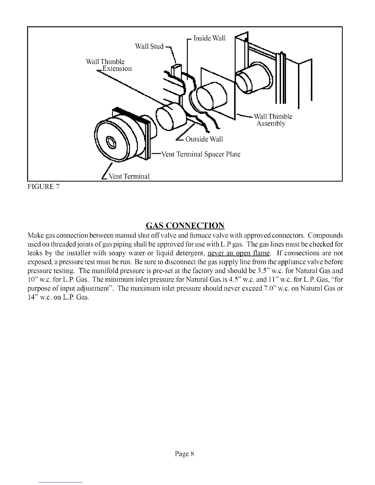
Slide the vent terminal onto the exhaust tube and the air intake tube. Secure vent terminal and vent terminal spacer plate to walt
providing a slight downward slope to the vent tubes. This will prevent water froln entering. Anchors (not provided) may be
required. Caulk around the vent terminal spacer plate with putty provided. See FimJre 7. NOTE: Some flaming may be
necessary to provide a flat surface for the vent terminal spacer plate to butt against, so rain cannot enter through cut out.
INSTALLING FURNACE- 15" TO 24" WALLS (CDV151CDV25-B). For
15" to 24" wall use only Vent Kit No. VK1525/15-24-B. Do not attempt to lengthen the exhaust robe, air intake tube, or wall
thimble extension provided with furnace. The VK1525/15-24-B Vent Kit has a one inch restrictor in the exhaust robe which is
necessary for proper and safe operation of this furnace. Do not use any other vent kit. Disconnect the air intake tube and the
exhaust tube fiom the back of the furnace and discard, see Fimlre 6. Install the exhaust tube and air intake tube from Vent Kit No.
VK1525/15-24-B. Discard the 5" telescoping wall thimble extension that surrounds the wall thimble asselnbly. Center the wall
thimble asselnbly in the 9" opening and attach to inside wall using eight (8) screws. Install furnace flush to wall by sliding
exhaust robe and air intake robe through the wall thimble assembly. Secure the furnace to the wall with screws through each of
the four holes in the mounting brackets located on the back of the furnace. These holes are spaced so as to allow the screws to
enter into studs that are on 16-inch centers. On certain types of walls, anchors (not provided) may be required. From outside the
building install the wall thilnble extension, Part No. 43730, supplied in Vent Kit No. VK1525/15-24-B by sliding it through the
cut out and over the wall thilnble extension. For walls 15" to 19" the wall thimble extension, air intake robe, and the exhaust robe
must be trimmed even with the outside walt. Slide the vent terminal onto the exhaust tube and into the air intake tube. Secure
vent terminal and vent terminal spacer plate to wall providing a slight downwmd slope to the vent tubes. This will prevent water
from entering. Anchors (not provided) may be required. Caulk around the vent terminal spacer plate with putty provided, see
Fire,re 7. NOTE: Some fiaming may be necessary to provide a flat surf:ace for the vent terminal spacer plate to butt against, so
rain cannot enter through the cut out.
INSTALLING FURNACE- 9 TO 15" WALLS (CDV33-B). For9"to 15"walluse Vent
. r
Kit No. VK33/9-15-B. Do not attempt to lengthen the exhaust tube, air intake tube, or wall thimble extension provided with
furnace or the VK33/9-15-B Vent Kit. Disconnect the air intake tube, and the exhaust tube from the back of the furnace and
discard. See Figure 6. Replace with exhaust tube and air intake tube from Kit No. VK33/9-15-B. Discard the 5" telescoping wall
thimble extension that surrounds the wall thimble assembly. Center the wall thimble assembly in the 9" opening and attach to
inside wall using eight (8) screws. Install furnace flush to walt by sliding exhaust tube and air intake robe through the wall
thilnble asselnbly. Secure the furnace to the wall with screws through each of the four holes in the mounting brackets located on
the back of the furnace. These holes are spaced so as to allow the screws to enter into studs that are on 16-inch centers. On
certain types of wall, anchors (not provided) may be required. From outside the building install the thick wall thimble extension,
Part No. 43835, supplied in Vent Kit No. VK33/9-15-B by sliding it through the cut out and over the wall thimble assembly. The
wall thimble extension should be even with the outside walt (some trimlning may be necessary). Slide the vent terminal onto the
exhaust tube and the air intake tube. Secure vent terminal and vent terminal spacer plate to wall providing a slight downward
slope to the vent robes. This will prevent water fiom entering. Anchors (not provided) may be required. Caulk around the vent
terminal spacer plate with putty provided. See Fibre 7. NOTE: Some fiaming may be necessary to provide a flat surfhce f\_rthe
vent terminal spacer plate to butt against, so rain cannot enter through cut out.
Page 6