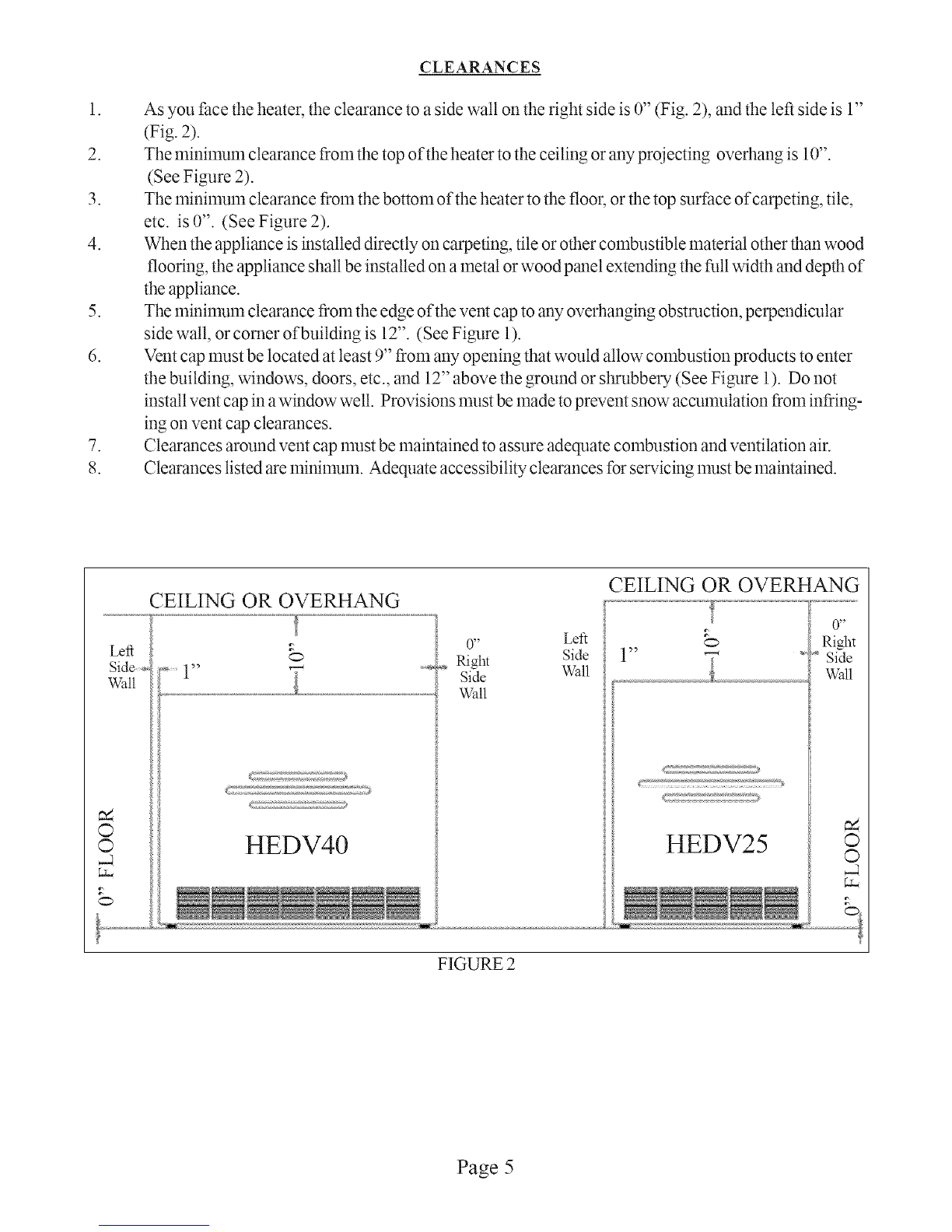
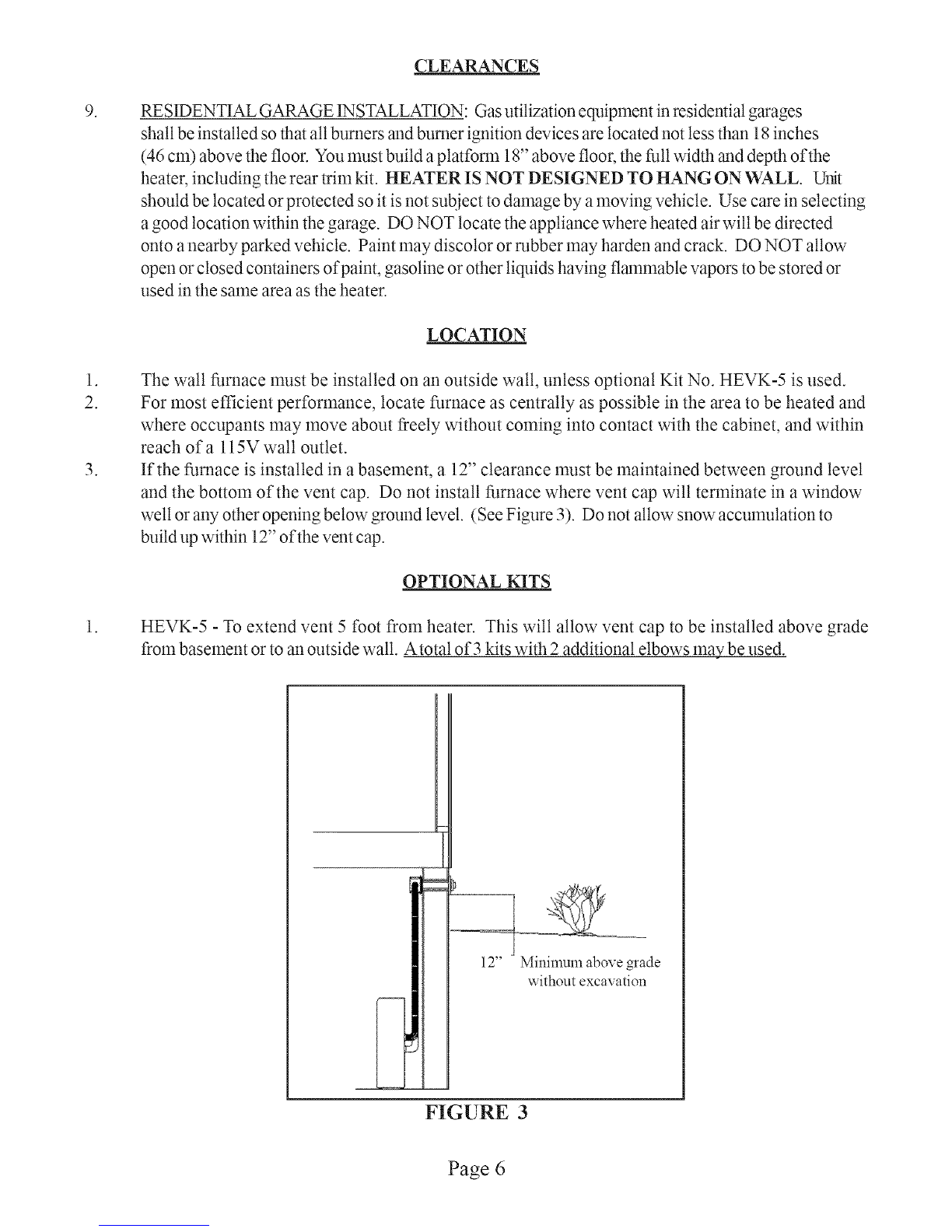
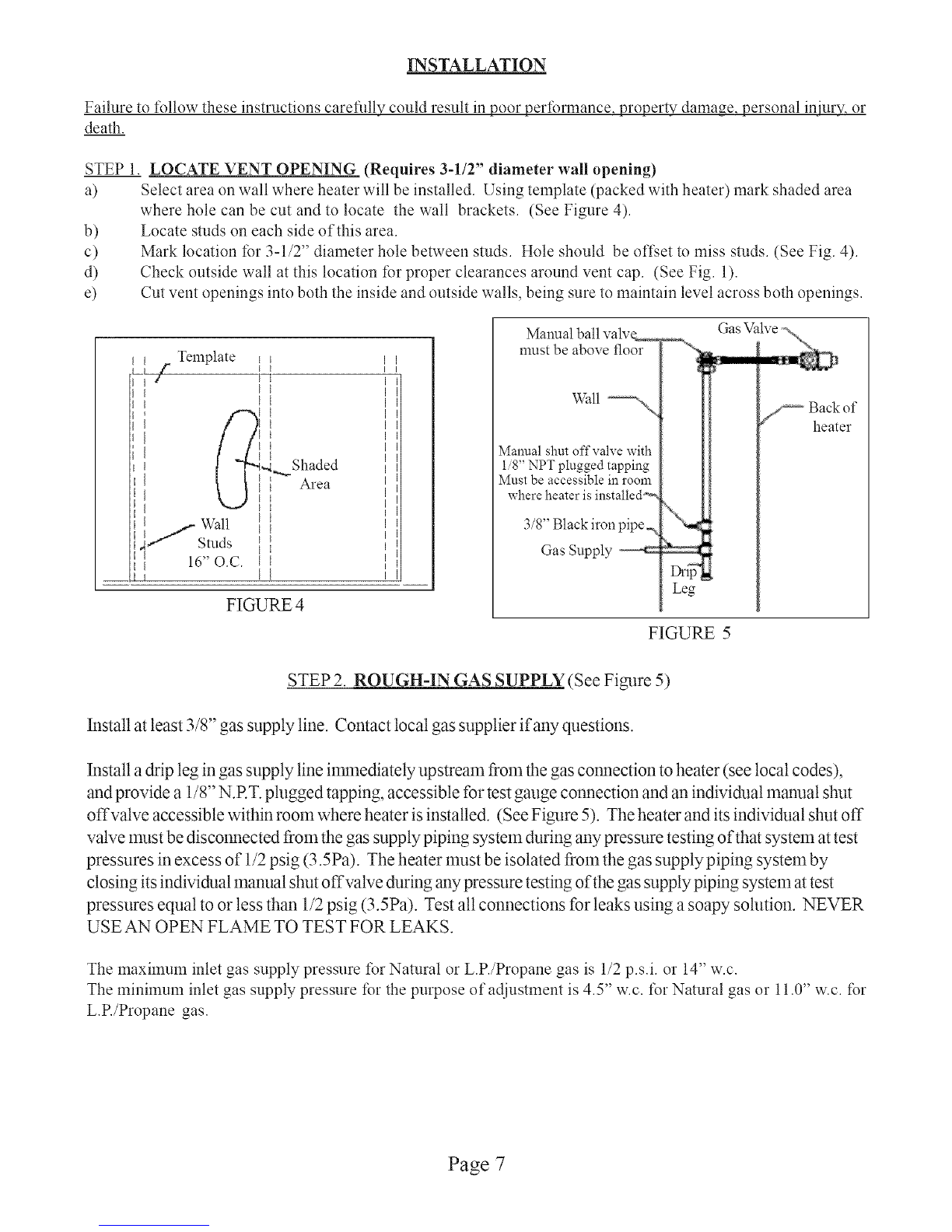
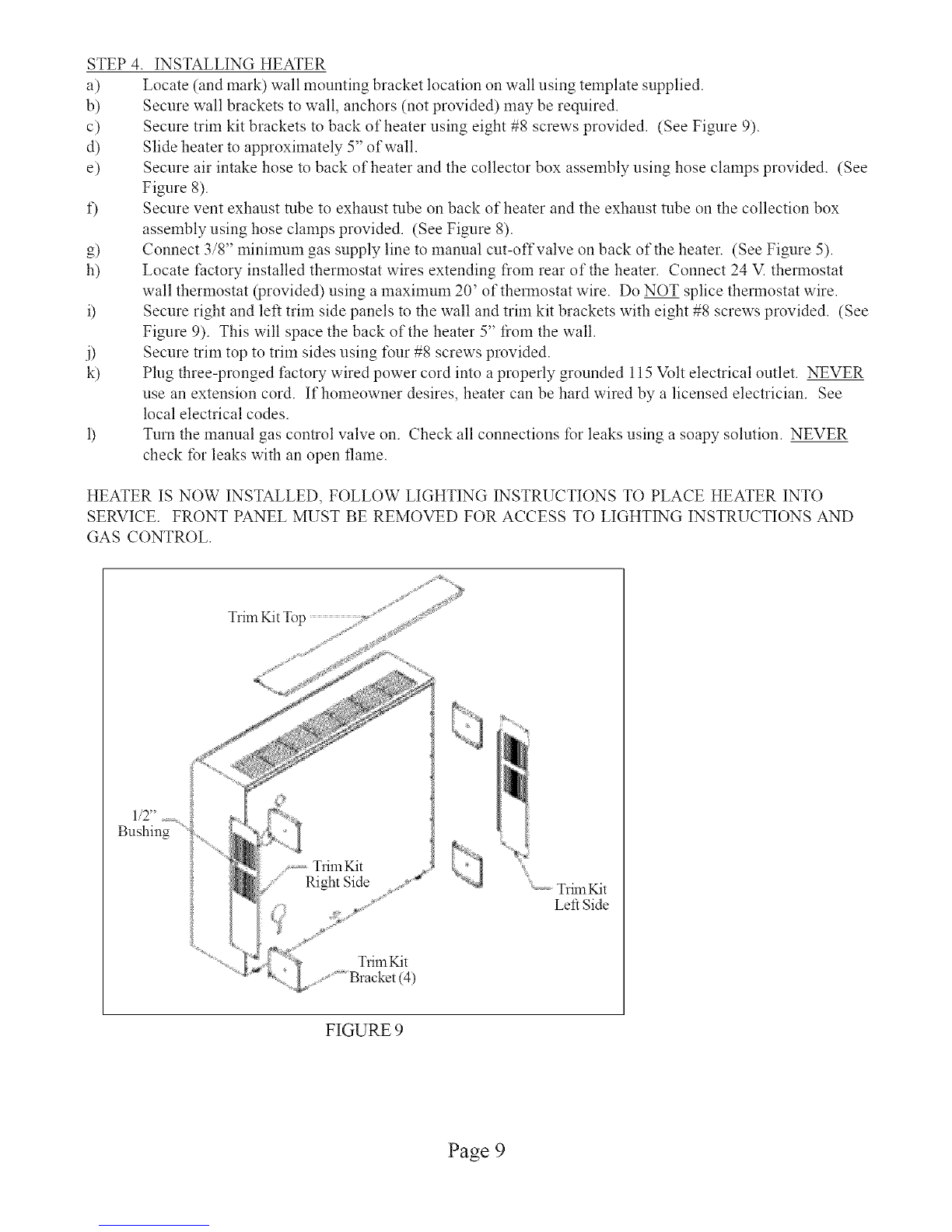
manuals.online logo
Brands
  1. Home
  2. •
  3. Brands
  4. •
  5. COZY
  6. •
  7. Wall Furnace
  8. •
  9. COZY HEDV254A and User manual

COZY HEDV254A and User manual

This manual suits for next models

3

Other COZY Wall Furnace manuals

COZY HEDV404 and User manual

COZY

COZY HEDV404 and User manual

COZY CF553D-H User manual

COZY

COZY CF553D-H User manual

COZY DVCF407B-R and User manual

COZY

COZY DVCF407B-R and User manual

COZY DVCF403C-H User manual

COZY

COZY DVCF403C-H User manual

COZY DVCF653B-H and User manual

COZY

COZY DVCF653B-H and User manual

COZY HEDV253A and User manual

COZY

COZY HEDV253A and User manual

COZY CDV155DPPD User manual

COZY

COZY CDV155DPPD User manual

COZY CDV155B and User manual

COZY

COZY CDV155B and User manual

COZY DVCF40 User manual

COZY

COZY DVCF40 User manual

COZY DVCF403C-H User manual

COZY

COZY DVCF403C-H User manual

COZY CDV15 User manual

COZY

COZY CDV15 User manual

COZY CDV335C User manual

COZY

COZY CDV335C User manual

COZY FSK-A User manual

COZY

COZY FSK-A User manual

COZY CF557C-H and User manual

COZY

COZY CF557C-H and User manual

COZY CF403D-H User manual

COZY

COZY CF403D-H User manual

COZY W255G User manual

COZY

COZY W255G User manual

COZY CDV155B and User manual

COZY

COZY CDV155B and User manual

Popular Wall Furnace manuals by other brands

Empire DV215SGXLP-2 Installation instructions and owner's manual

Empire

Empire DV215SGXLP-2 Installation instructions and owner's manual

Empire Heating Systems FAN TYPE VENTED WALL FURNACE FAW-55IP Installation instructions and owner's manual

Empire Heating Systems

Empire Heating Systems FAN TYPE VENTED WALL FURNACE FAW-55IP Installation instructions and owner's manual

Empire DV-55IP Installation instructions and owner's manual

Empire

Empire DV-55IP Installation instructions and owner's manual

Empire Heating Systems MV 145 Installation instructions and owner's manual

Empire Heating Systems

Empire Heating Systems MV 145 Installation instructions and owner's manual

Empire DV-20E-5 Installation instructions and owner's manual

Empire

Empire DV-20E-5 Installation instructions and owner's manual

USSC 9660 user manual

USSC

USSC 9660 user manual

Empire Heating Systems DV210SGXLP-1 Installation instructions and owner's manual

Empire Heating Systems

Empire Heating Systems DV210SGXLP-1 Installation instructions and owner's manual

Williams 6008532 owner's manual

Williams

Williams 6008532 owner's manual

Braemar WF2000 user manual

Braemar

Braemar WF2000 user manual

Empire FAW40IPXLP-1 Installation instructions and owner's manual

Empire

Empire FAW40IPXLP-1 Installation instructions and owner's manual

Empire Heating Systems DV-35-2SG Installation instructions and owner's manual

Empire Heating Systems

Empire Heating Systems DV-35-2SG Installation instructions and owner's manual

Empire Heating Systems GWT-25-2 SG Installation instructions and owner's manual

Empire Heating Systems

Empire Heating Systems GWT-25-2 SG Installation instructions and owner's manual

Empire Heating Systems GWT-25-2 SG Installation instructions and owner's manual

Empire Heating Systems

Empire Heating Systems GWT-25-2 SG Installation instructions and owner's manual

Empire Heating Systems DVC55SPPXLP-1 Installation instructions and owner's manual

Empire Heating Systems

Empire Heating Systems DVC55SPPXLP-1 Installation instructions and owner's manual

Empire Heating Systems DVC55SPPXLP-2 Installation instructions and owner's manual

Empire Heating Systems

Empire Heating Systems DVC55SPPXLP-2 Installation instructions and owner's manual

Napoleon GDS3700-N Installation and operation instructions

Napoleon

Napoleon GDS3700-N Installation and operation instructions

HouseWarmer HWDV080DVN-1 owner's manual

HouseWarmer

HouseWarmer HWDV080DVN-1 owner's manual

Empire Heating Systems PVS18(N Owner's manual and installation instructions

Empire Heating Systems

Empire Heating Systems PVS18(N Owner's manual and installation instructions

manuals.online logo
manuals.online logoBrands
  • About & Mission
  • Contact us
  • Privacy Policy
  • Terms and Conditions

Copyright 2025 Manuals.Online. All Rights Reserved.

HI-[FFIC|EHT T
VEHTWALLFUR#ACE
INSTALLATION AND
OPERATING INSTRUCTIONS
P/N 72903 August 2007
MODEL NUWIBERS
NAT. GAS HEDV253A
L.E GAS HEDV254A
HEDV403A
HEDV404A
INSTALLER: Leave this manual with the appliance
CONSUMER: Retain this manual for future
reference.
Remove cabinet to access gas control knob.
WARNING: If the information in these instructions are
not followed exactly, a fire or explosion may result
causing property damage, personal injury or loss of life.
Do not store or use gasoline or other flammable vapors
and liquids in the vicinity of this or any other appliance.
WHAT TO DO IF YOU SMELL GAS:
• Do not try to light any appliance.
• Do not touch any electrical switch; do not use any
phone in your building.
• hnmediatety call your gas supplier from a neighbor's
phone. Follow the gas supptier's instructions.
• If you cannot reach your gas supplier, call the
fire departlnent.
INSTALLATION AND SERVICE MUST BE PER-
FORMED BY A QUALIFIED INSTALLER,
SERVICE AGENCY OR THE GAS SUPPLIER. NADE _N UoS_A_
WARNING: Operation of this furnace without the properly installed, factory furnished vent system and vent
cap could result in Carbon Monoxide (CO) poisoning and possible death. For your safety, this furnace and
the vent system should be inspected at least ammalty by a qualified se_wice person.
This appliance may be installed in an aftennarket, permanently located, manufactured home (USA only) or
mobile home, where not prohibited by local codes.
This appliance is only for use with the type of gas indicated on the rating plate. This appliance is not
convertible for use with other gases, unless a certified kit is used.
This unit is not approved for installation in greenhouses, or environments involving dusty, wet,
corrosive, or explosive conditions. Such conditions will invalidate the warranty and may create
unsafe conditions.
performedbyaplumber or gas fitter licensed in the Commonwealth of Massachusetts.
Intro&lction...................................... 2
Specifications and Dimensions ............. 2
Sat}tyRules........................................ 3
Clearm_ces....................................... 4/5
D3cation.......................................... 6/7
Installation....................................... 7/9
Lighting Instructions ......................... 10
Burner Orifice................................... 11
CONTENTS Removing Main Burner ...................... 11
Proper Burner Flmnc........................... 11
WiringDiagrmn.................................. 12
Sequence of Operation ...................... 13
OptionalKits.................................. 14/16
Maintenance Instr./Service Record ...... 17
Trouble Shooting............................... 18/19
PartsDrawing................................... 20
Paris List .......................................... 21
Warrmlty.................................................... 22
INTRODUCTION
THIS IS A GAS-FIRED DRAFT INDUCED, POWER DEPENDENT DIRECT VENT WALL FURNACE
THAT WILL OPERATE SAFELY AND PROVIDE AN EFFICIENT SOURCE OF HEAT WHEN
INSTALLED, OPERATED AND MAINTAINED AS RECOMMENDED IN THESE INSTALLATION AND
OPERATING INSTRUCTIONS. READ THESE INSTRUCTIONS THOROUGHLY BEFORE INSTALLINQ
SERVICING, OR USING THE APPLIANCE. IF YOU DO NOT U2qDERSTAND ANY PART OF THESE
INSTRUCTIONS CONSULT LOCALAUTHORITIES, OTHER QUALIFIED INSTALLERS, SERVICE
AGENCIES, THE GAS SUPPLIER OR THE MANUFACTURER.
SPECIFICATIONS AND DIMENSIONS
Your Direct Vent Wall Furnace is shipped complete in one carton. This carton contains the furnace, vent cap,
collector box, vent exhaust tube, air inlet tube, wall template with rough-in dimensions, installation and operating
instructions, and wall thermostat.
Model
No.
HEDV253A
HEDV403A
HEDV254A
HEDV404A
Input
BTU/HR
25,000
40,000
25,000
40,000
Weight Width Depth
100Lbs. 24-1/2"
120Lbs. 34-5/8"
100Lbs. 24-1/2"
120Lbs. 34-5/8"
9-3/4"
9-3/4"
9-3/4"
9-3/4"
Type
Height Control
NATURALGAS
" 24_
2-1/4
0-1/2 24M
LE GAS
32-1/4" 24V
30-1/2" 24V
CFM
200
500
200
5O0
AMPS
1.88
2.18
1.88
2.18
Center
Gas Vent MAX. MIN.
Conn. to Floor Wall Wall
(Adj.) THICKNESS
3/8" 12-1/2"
3/8" 12-1/2"
3/8" 12-1/2"
3/8" 12-1/2"
32" 5"
32" 5"
32" 5"
32" 5"
Page 2
SAFETY RULES
,
2.
3.
4.
5.
6.
7.
8.
9.
10.
11.
12.
13.
14.
15.
16.
17.
18.
19.
20.
21.
22.
23.
24.
25.
26.
Improper installation, adjustment, alteration, service, or maintenance can cause property damage, bodily
injury, or death.
Use in other than a residential application may result in unsatisfactory performance, may create unsafe
conditions and will invalidate the warranty.
The installation must conform with local codes or in the absence of local codes wtih the National Fuel Gas
Code, ANSI Z223.1/NFPA 54, Natural Gas and Propane Installation Code, CSA B149.1.
DO NOT INSTALL THIS FURNACE IN A RECREATIONAL VEHICLE OR TRAILER.
Do not operate wall furnace unless it is connected to the factory supplied vent system with vent cap in
place.
Check the rating label attached to the wall furnace to be sure it is equipped for the type gas you intend to
use.
Never use a match, candle, flame or other source of ignition to check for gas leaks. Use only soapy water
or liquid detergent.
Have your wall furnace and vent system inspected at least annually by a qualified service technician.
Before cleaning or servicing, turn off the gas and allow furnace to cool.
Do not operate wall furnace without all components properly installed (top, fiont, etc.).
Due to high temperatures, the appliance should be located out of traffic and away from furniture and
Children and adults should be alerted to the hazards of high surface temperature and should stay away
to avoid burns or clothing ignition.
Young children should be carefully supervised when they are in the same room as the appliance.
Clothing or other flammable material should not be placed on or near the appliance.
INSTALLATION AND REPAIR SHOULD BE DONE BY A OUALIFIED SERVICE PERSON. THE
APPLIANCE SHOULD BE INSPECTED BEFORE USE AND AT LEAST ANNUALLY BY A
£)UALIFIED SERVICE PERSON. More frequent cleaning may be required due to excessive lint from
carpeting, bedding material, etc. It is imperative that control compartments, burners, and circulating air
passageways of the appliance be kept clean.
Do not install in a closet, alcove, or small hallway where the furnace could be isolated from the space to
be heated by closing a door.
Do not put anything around the furnace or vent cap that will obstruct the flow of combustion and
ventilation air.
The appliance, when installed, must be electrically grounded in accordance with local codes or, in the
absence of local codes, with the latest edition of National Electrical Code, ANSI/NFPA 70, or Canadian
Electrical Code, CSA C22.1, if an external electrical source is utilized.
Never operate this furnace without the sight glass in place or with the glass broken or missing.
If it is suspected that rising water may enter the furnace, turn off the gas immediately.
Do not use this appliance if any part has been under water. Immediately call a qualified service technician
to inspect the appliance and to replace any part of the control system and any gas control which has
been under water.
It is necessary to replace damaged gaskets or sealing material within the vent or air intake system. Faifure
to do so may result in property damage, personal iNmy or loss of life.
Any safety screen or guard removed for servicing must be replaced prior to operating heater.
A gas appliance must not be connected to a chinmey flue serving a separate solid fuel burning appliance.
The appliance area must be kept clear and free from combustilbe materials, gasoline and other flammable
vapors and liquids.
Any safety screen or guard removed for servicing an appliance must be replaced prior to operating the
appliance.
Page 3
FIGURE 1
Vent Terminal _ Air Supply Inlet [] Area where terminal is not permitted
VENT TERMINAL CLEARANCES
REFERENCELETTERTO
DRAWING
A = Clearance above grade,
veranda, porch, deck, or
balcony
B = Clearance to window or door
that may be opened
C = Clearance to permanently
closed window
D = Vertical clearance to
ventilated soffit located above
the terminal within a horizontal
distance of 2 Feet (61 cm) from
the center line of the terminal
E= Clearance to unventilated
soffit
F = Clearance to outside corner
G = Clearance to inside corner
H = Clearance to each side of
center line extended above
meter/regulator assembly
I = Clearance to service regulator
vent outlet
J = Clearance to nonmechanical
air supply inlet to building or the
combustion air inlet to any other
appliance
K = Clearance to a mechanical
air supply inlet
L= Clearance above paved
sidewalk or paved driveway
located on public property
M = Clearance under veranda,
porch, deck, or balcony
CANADIAN
INSTALLATIONSI
12 Inches (30 cm)
12 Inches (30 cm)
12 Inches (30 cm)
18 Inches (46 cm)
18 Inches (46 cm)
12 Inches (30 cm)
12 Inches (30 cm)
3 Feet (91 cm) within a height
15 Feet (4.5m) above the
meter/regulator assembly
3 Feet (91 cm)
12 Inches (30 cm)
6 Feet (1.83 m)
7 Feet (2.13m) Avent shall
not terminate directly above
a sidewalk or paved driveway
that islocated between two
single family dwellings and
serves both dwellings.
12 Inches (30cm) permitted
only if veranda, porch, deck,
or balcony isfully open on a
minimum of two sides.
U.S. INSTALLATIONS2
12 Inches (30 crn)
9 Inches (23 cm)
9 Inches (23 cm)
18 Inches (46 cm)
18 Inches (46 cm)
12 Inches (30 cm)
12 Inches (30 cm)
Clearances are in accordance
with local installation codes and
the requirements of the gas
supplier
Clearances are in accordance
with local installation codes and
the requirements of the gas
supplier
12 Inches (30 cm)
3 Feet (91 cm) above if within
10 Feet (3 m) horizontally
Clearances are in accordance
with local installation codes and
the requirements of the gas
supplier.
Clearances are in accordance
with local installation codes and
the requirements of the gas
supplier.
In accordance with the current CSA-B149.1 Natural Gas and Propane Installation Code
2 In accordance with the current ANSI Z223.1 /NFPA 54 National Fuel Gas Code
Page 4
.
2.
3.
4.
.
6.
.
8.
CLEARANCES
As you Pace the heater, the clearance to a side watt on the right side is 0" (Fig. 2), and the left side is 1"
(Fig. 2).
The minimum clearance from the top of the heater to the ceiling or any projecting overhang is 10".
(See Figure 2).
The minimum clearance from the bottom of the heater to the floo_; or the top surface of carpeting, tile,
etc. is 0". (See Figure 2).
When the appliance is installed directly on carpeting, tile or other combustible material other than wood
flooring, the appliance shall be installed on a metal or wood panel extending the full width and depth of
the appliance.
The minimum clearance from the edge of the vent cap to any overhanging obstruction, perpendicular
side wall, or comer of building is 12". (See Figure 1).
Vent cap must be located at least 9" from any opening that would allow combustion products to enter
the building, windows, doors, etc., and 12" above the ground or shrubbel T (See Figure 1). Do not
install vent cap in awindow well. Provisions must be made to prevent snow accumulation from infring-
ing on vent cap clearances.
Clearances around vent cap must be maintained to assure adequate combustion and ventilation air.
Clearances listed are minimum. Adequate accessibility clearances for servicing must be maintained.
CEILING OR OVERHANG
Side_
V_all
0
0
0
0" Left
1" Right Side
Side V_all
Wa!!
HEDV40
CEILING OR OVERHANG
0
<2_2:7/
0 _
Right
Side
Wall
HEDV25 c
c
C
FIGURE 2
Page 5
.
.
2.
.
CLEARANCES
RESIDENTIAL GARAGE INSTALLATION: Gas utilization equipment in residential garages
shall be installed so that all burners and burner ignition devices are located not less than ! 8 inches
(46 cm) above the floor. You must build a platform 18" above floor, the full width aa_ddepth of the
heatec including the rear trim ldt. HEATER IS NOT DESIGNED TO HANG ON WALL. Unit
should be located or protected so it is not subject to damage by a moving vehicle. Use care in selecting
a good location within the garage. DO NOT locate the appliance where heated air will be directed
onto a nearby parked vehicle. Paint may discolor or rubber may harden and crack. DO NOT allow
open or closed containers of paint, gasoline or other liquids having flmnmable vapors to be stored or
used in the same area as the heater.
LOCATION
The wall furnace must be installed on an outside wall, unless optional Kit No. HEVK-5 is used.
For most efficient performance, locate furnace as centrally as possible in the area to be heated and
where occupants may move about freely without coming into contact with the cabinet, and within
reach ofa l15V wall outlet.
If the furnace is installed in a basement, a 12" clearance must be maintained between ground level
and the bottom of the vent cap. Do not install furnace where vent cap will terminate in a window
welt or any other opening below grotmd level. (See Figure 3). Do not allow snow accumulation to
build up within 12" of the vent cap.
OPTIONAL KITS
HEVK-5 - To extend vent 5 foot from heater. This wilt allow vent cap to be installed above grade
from basement or to an outside wall. Atotal of 3 kits with 2 additional elbows may be used.
12" Minimum above grade
without excavation
FIGURE 3
Page 6
INSTALLATION
Failure to follow these instructions carefilllv could result in poor performance, property damage, personal injury, or
death.
STEP 1. LOCATE VENT OPENING (Requires 3-112" diameter wall opening)
a) Select area on wall where heater will be installed. Using template (packed with heater) mark shaded area
b)
c)
d)
e)
where hole can be cut and to locate the wall brackets. (See Figure 4).
Locate studs on each side of this area.
Mark location for 3-1/2" diameter hole between studs. Hole should be oft;et m miss studs. (See Fig. 4).
Check outside wall at this location for proper clearances around vent cap. (See Fig. 1).
Cut vent openings into both the inside and outside walls, being sure to maintain level across both openings.
I__ [
L_l g" I I
d
iI
Template _L
b
It Shaded
Area
j Wall
Studs
II16" O.C.
FIGURE 4
Manual ball valv_
must be above floor
V,?a11_.,,
Manual shin offvalve with
1/8" NPT plugged tapping
Must be accessible in room
where heater is installed _
./8 Blackiron pipe_.
Gas Supply
Leg
j_ Back of
heater
FIGURE 5
STEP 2. ROUGH-IN GAS SUPPLY (See Figure 5)
Install at least _/8 gas supply line. Contact local gas supplier if any questions.
Install a drip leg in gas supply line immediately upstream from the gas connection to heater (see local codes),
and provide a 1/8" N.RT. plugged tapping, accessible for test gauge connection and an individual manual shut
offvalve accessible within room where heater is installed. (See Figure 5). The heater and its individual shut off
valve must be disconnected from the gas supply piping system during any pressure testing of that system at test
pressures in excess of 1/2 psig (3.5Pa). The heater must be isolated from the gas supply piping system by
closing its individual manual shut offvatve during any pressure testing of the gas supply piping system at test
pressures equal to or less than 1/2 psig (3.5Pa). Test all connections for leaks using a soapy solution. NEVER
USE AN OPEN FLAME TO TEST FOR LEAKS.
The maxmmm inlet gas supply pressure for Natural or L.P./Propane gas is 1/2 p.s.i, or 14" w.c.
The minimum inlet gas supply pressure for the purpose of adjustment is 4.5" w.c. for Natural gas or 11.0" w.c. for
L.P./Propane gas.
Page 7
INSTALLATION - CONTINUED
STEP3
a)
b)
c)
d)
INSTALLING VENT SYSTEM 5" - 32" WALL THICKNESS (12.7 cm - 81.3 cm)
Use only factory supplied parts. Do not attempt to modify in any way. To do so could cause a system
imbalance resulting in poor performance and/or unsafe operating conditions.
Slide collection box pipes through cutout and secure collection box to inside wall. Anchors (not supplied)
may be required. (See Figure 5).
From outside house, mark collection box pipes and cut off 1/2" beyond outside wall.
Slide vent cap pipes onto collection box pipes and push in until flange is flush against house. Secure vent
cap assembly to outside wall with a slight downward slope. This will prevent water from entering and
allow condensation to drain. Caulk around the edges of the vent cap mounting plate. NOTE: It may
be necessary to build a metal or wood frame to provide a flat surthce for the mounting plate to be flush
against or to attain the 5" minimuln wall thickness.
Trim Kit Brackets
Gas Inlet
Air Intake
,///-- Fine Ontlet
(i49 cm)
HEDV25 - Figure 6 FIGURE 5
Trim Kit Brackets------.
Gas Inlet
-- Air Intake
..... ......
(i56 cm)
HEDV40 - Figure 6
Collection Box _,_
Assembly
Vent Cap
sembly
Vent Cap
Mounting
Plate
FIGURE 7 FIGURE 8
Page 8
STEP 4.
a)
b)
c)
d)
e)
,3
g)
h)
J)
k)
INSTALLING HEATER
Locate (and mark) wall mounting bracket location on wall using template supplied.
Secure wall brackets to wall, anchors (not provided) may be required.
Secure trim kit brackets to back of heater using eight #8 screws provided. (See Figure 9).
Slide heater to approximately 5" of wall.
Secure air intake hose to back of heater and the collector box assembly using hose clamps provided. (See
Figure 8).
Secure vent exhaust tube to exhaust tube on back of heater and the exhaust tube on the collection box
assembly using hose clamps provided. (See Figure 8).
Connect 3/8" minimum gas supply line m manual cut-offvalve on back of the heater. (See Figure 5).
Locate factory installed thermostat wires extending from rear of the heater. Connect 24 _ thermostat
wall thermostat (provided) using a maximum 20' of thermostat wire. Do NOT splice thermostat wire.
Secure right and left trim side panels to the wall and trim kit brackets with eight #8 screws provided. (See
Figure 9). This will space the back of the heater 5" from the wall.
Secure trim top to trmr sides using four #8 screws provided.
Plug three-pronged factory wired power cord into a properly grounded 115 Volt electrical outlet. NEVER
use an extension cord. If homeowner desires, heater can be hard wired by a licensed electrician. See
local electrical codes.
Turn the manual gas control valve on. Check all connections for leaks using a soapy solution. NEVER
check for leaks with an open flame.
HEATER IS NOW INSTALLED, FOLLOW LIGHTING INSTRUCTIONS TO PLACE HEATER INTO
SERVICE. FRONT PANEL MUST BE REMOVED FOR ACCESS TO LIGHTING INSTRUCTIONS AND
GAS CONTROL.
1/2"
Bushing
Trim Kit
(4)
_...........TrimKit
Left Side
FIGURE 9
Page 9
_FOR YOUR SAFETY READ BEFORE OPERATING 1
WARNING: If you do not follow these instructions exactly, a fire or explosion may result
causing property damage, personal injury or loss of life.
A,
B,
This appliance does not have a pilot. It is
equipped with an ignition device which
automatically lights the burner. Do not try
to light the buruer by hand.
BEFORE OPERATING smell all around the
appliance area for gas. Be sure to smell next
to the floor because some gas is heavier than
air and will settle on the floor.
C,
•If you cannot reach your gas supplier, call
the fire department.
Use only your hand to push in or turn the gas
control knob. Never use tools. If the knob will
not push in or turn by hand, don't try to repair
it, call a qualified service technician. Force or
attempted repair may result in a fire or explosion.
WHAT TO DO IF YOU SMELL GAS:
•Do not try to light any appliance.
• Do not touch any electric switch; do not
use any phone in your building.
• hnmediately call your gas supplier from a
neighbor's phone. Follow the gas supplier's
instructions.
D. Do not use this appliance if any part has been
under water. Immediately call a qualified service
technician to inspect the appliance and to
replace any part of the control system and any
gas control which has been under water.
OPERATING INSTRUCTIONS
l,
2.
3.
4..
.
6.
STOP! Read safety information on this label. 7.
Set the thermostat to the lowest setting.
Turn off all electric power to the appliance.
This appliance is equipped with an ignition device
which automatically lights the burner. Do not try 8.
to light the burner by hand.
Remove cabinet to access gas control knob. 9.
Turn gas control knob clockwise g'N to 10.
"ofF'. Do not force. 11.
Gas control knob
in "OFF" position
12.
Wait five (5) minutes to clear out any gas. If
you smell gas, STOP! Follow "B" in safety
information on this label. If you don't smell
gas, go to next step.
Turn gas control knob counterclockwise _'N
to "ON".
Turn on all electric power to the appliance.
Set thermostat to desired setting.
If the appliance does not operate, follow
instructions "To Turn Off Gas To Appliance"
and call your se_wice technician or gas
supplier.
Replace cabinet.
_TO TURN OFF GAS TO APPLIANCE
l.
2.
3.
Set the thermostat to lowest setting.
Turu off all electric power to the appliance if service is to be performed.
Turn gas control knob clockwise g'X to "OFF". Do not force.
Page 10