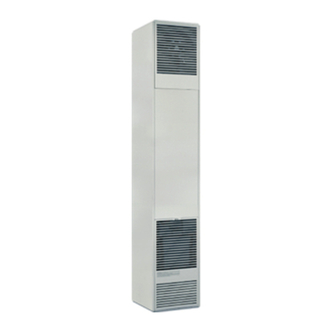
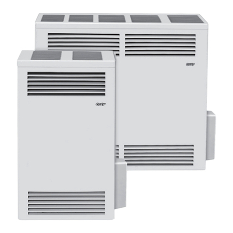
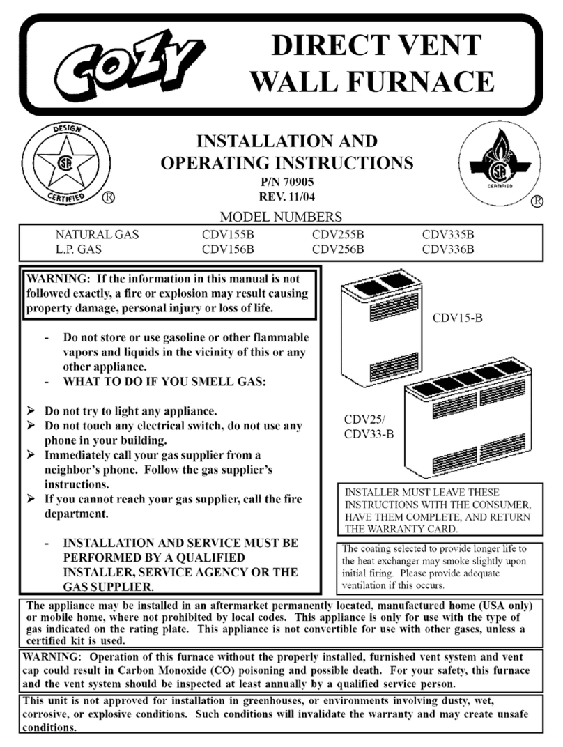
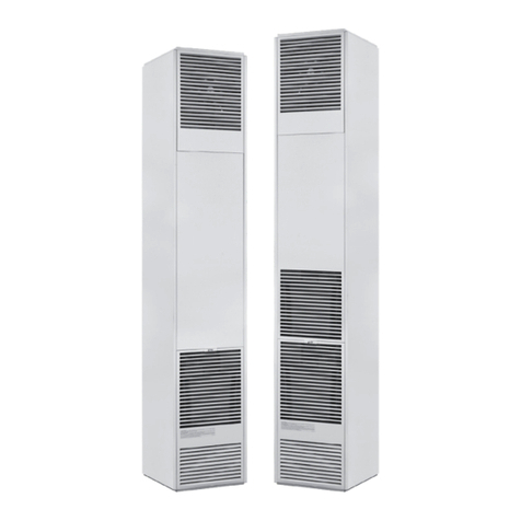
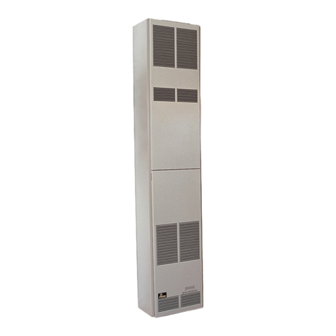
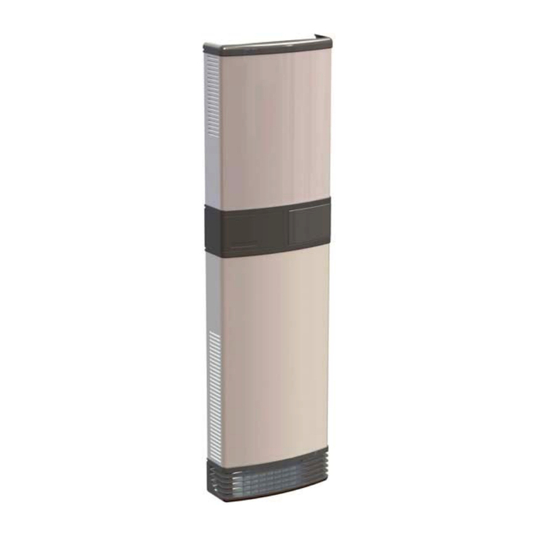
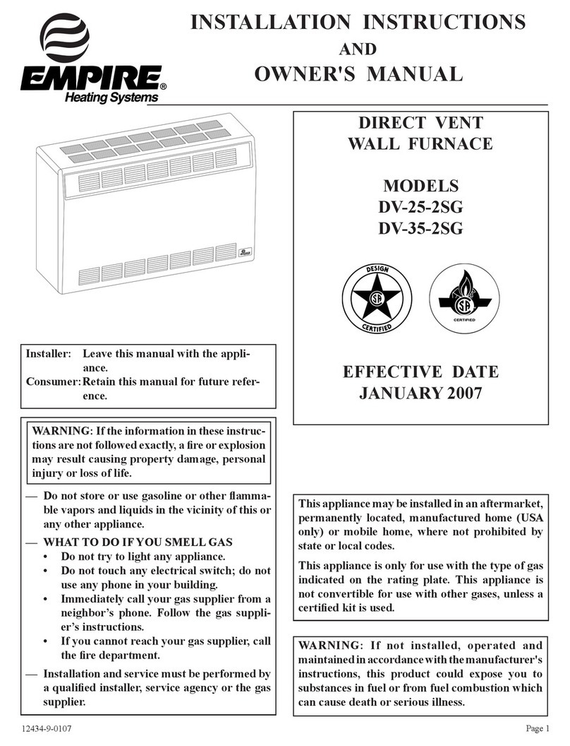
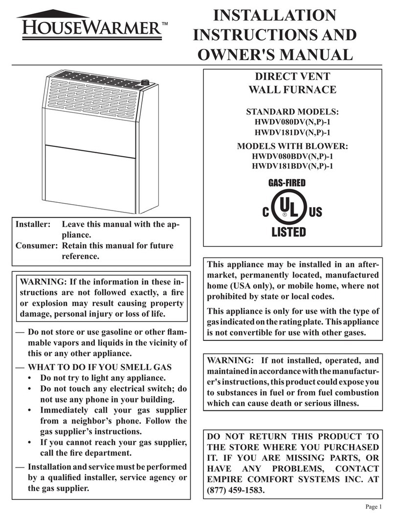
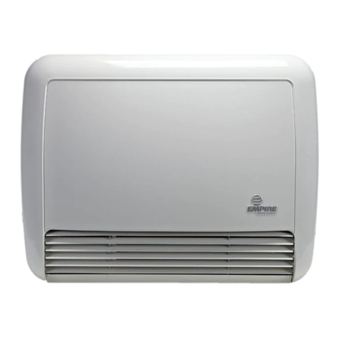
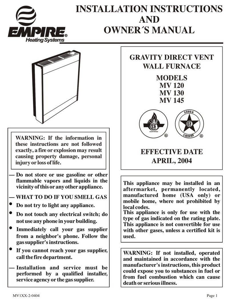
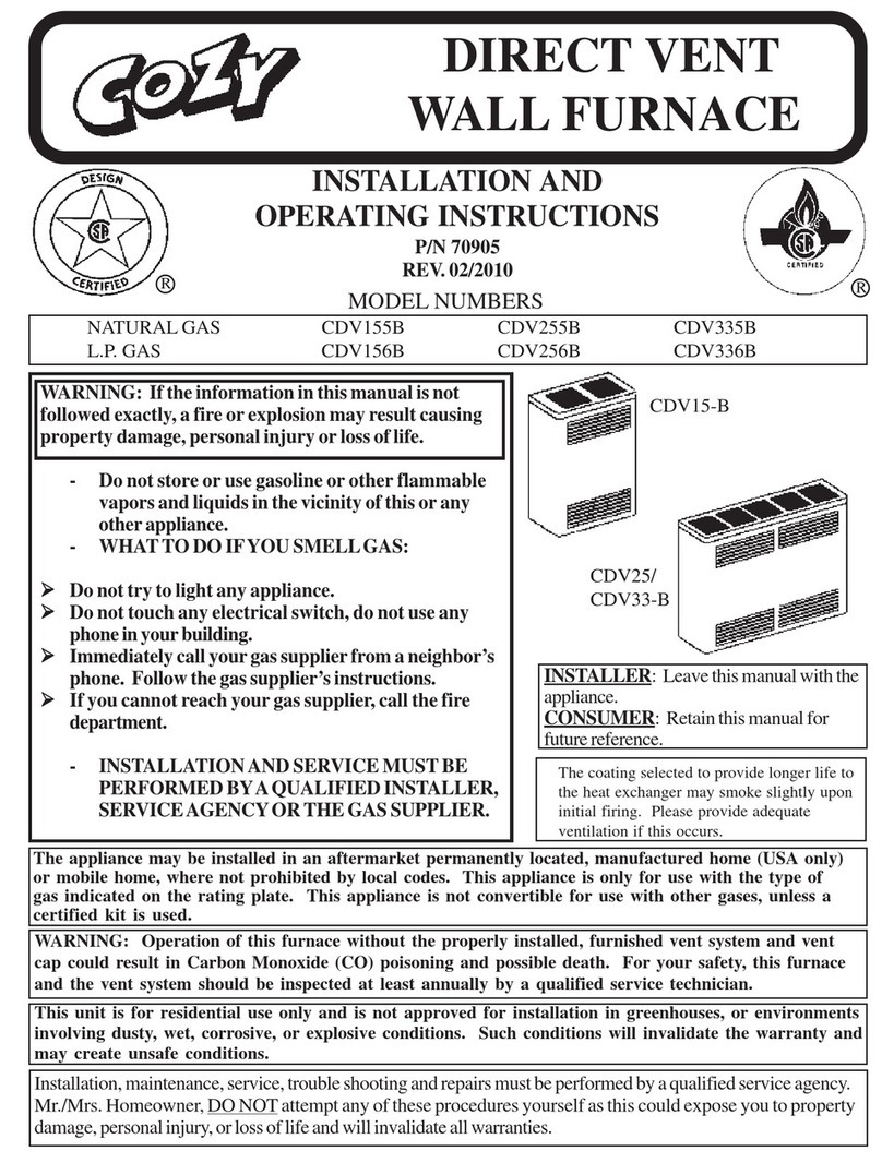
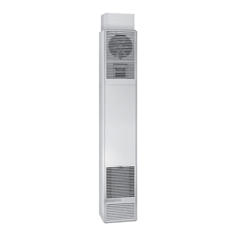
COZY CDV335C User manual

ENGLISH
Click here for the full manual or
click on the links below to quickly
locate what you’re looking for:
ESPAÑOL
Haga clic aquí para ver el manual
completo o haga clic en los
siguientes enlaces para localizar
rápidamente lo que está buscando:
FRANÇAIS
Cliquez ici pour le manuel complet
ou cliquez sur les liens ci-dessous
pour localiser rapidement ce que
vous recherchez:
Before Installation
Standards ............................................ 2
Specications ...................................... 3
Introduction ......................................... 3
Safety ............................................. 3 - 4
Venting ................................................. 4
Clearances .................................... 5 - 6
Special Precautions & Location ........... 6
Installation Steps ........................... 7 - 10
Gas Connection ................................. 10
Lighting Instructions ........................... 11
Pilot Adjustment ................................. 12
Burner Orice
& Orice Chart ................................... 13
Thermostat Installation ...................... 13
Removing Burner ............................... 14
Service Records ................................ 14
Troubleshooting Charts ..................... 15
DVB-3 Blower Installation ............ 16 - 17
BBSK Installation ............................... 18
BBSK Lighting Instructions ................ 19
Part List:
CDV155 & CDV156 .................... 20 - 21
CDV255, CDV256, CDV335 &
CDV356 ...................................... 22 - 23
Warranty ............................................ 24
Antes de la Instalación
Las Normas ......................................... 2
Especicaciones ................................... 3
Introducción ......................................... 3
Seguridad ......................................... 3 - 4
Ventilation ............................................. 4
Espacios Libres .............................. 5 - 6
Ubicación y Precauciones .................... 6
Pasos de Instalación ....................... 7 -10
Conexión de Gas ................................ 10
Instrucciones de Encendido ................ 11
Ajuste del Piloto .................................. 12
Espreas del Quemador y Diagrama
de Oricios ......................................... 13
Instalación del Termostato .................. 13
Quemador Principal ........................... 14
Registros de Servicio .......................... 14
Tabla de Localización de Problemas .. 15
Instalación del Soplador DVB-3 .... 16 -17
Instalación del BBSK .......................... 18
Encendido BBSK ................................ 19
Lista de Piezas:
CDV155 & CDV156 ..................... 20 - 21
CDV255, CDV256, CDV335 &
CDV356 ....................................... 22 - 23
Garantía .............................................. 24
Avant L’Installation
Les Normes ........................................ 2
Spécications ...................................... 3
Introduction ......................................... 3
Sécurité .......................................... 3 - 4
Ventilation ............................................ 4
Dégagements ................................ 5 - 6
Emplacement et Précautions ............... 6
Étapes D’installation ...................... 7 - 10
Connexion au Gaz ............................. 10
Instructions Pour L’allumage ............. 11
Réglace de la Veilleuse ..................... 12
Orice du brûleur et diagramme
d’orice .............................................. 13
Installation du Thermostat ................. 13
Enlever le Brûleur ............................. 14
Fiche de Service ................................ 14
Tableau de Dépannage ..................... 15
D’installation Soufeur DVB-3 .... 16 - 17
Installation du BBSK .......................... 18
Allumage du BBSK ............................ 19
Liste des Pièces:
CDV155 & CDV156 .................... 20 - 21
CDV255, CDV256, CDV335 &
CDV356 ...................................... 22 - 23
Garantie ............................................. 24
DIRECT VENT
WALL FURNACE
Installation and Operating Instructions
1017757-A_webcvr

1017757-APage 1
—Donotstoreorusegasolineorotherammable
vapors and liquids in the vicinity of this or any
other appliance.
— WHAT TO DO IF YOU SMELL GAS
•Donottrytolightanyappliance.
•Donottouchanyelectricalswitch;donotuse
anyphoneinyourbuilding.
•Immediatelycallyourgassupplierfroma
neighbor’sphone.Followthegassupplier’s
instructions.
•Ifyoucannotreachyourgassupplier,callthe
redepartment.
—Installationandservicemustbeperformedby
aqualiedinstaller,serviceagencyorthegas
supplier.
!WARNING:Iftheinformationinthese
instructionsisnotfollowedexactly,areor
explosionmayresultcausingpropertydamage,
personal injury or loss of life.
INSTALLER:Leavethismanualwiththeappliance.
CONSUMER:Retainthismanualforfuturereference.
DIRECT VENT
WALL FURNACE
Installation and Operating Instructions
Cozy Heating Systems, LLC | cozyheaters.com | 855-589-5380 | 3230 Industrial Pkwy | Jeffersonville, IN 47130
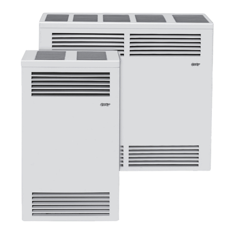
CDV15-C
CDV25-C
CDV33-C
The appliance may be installed in an aftermarket permanently located, manufactured home (USA only) or mobile home,
where not prohibited by local codes. This appliance is only for use with the type of gas indicated on the rating plate. This
appliance is not convertible for use with other gases, unless a certied kit is used.
- The coating selected to provide longer
life to the heat exchanger may smoke
slightly upon initial ring.Provide
adequate ventilation if this occurs.
- Installation, maintenance, service,
troubleshooting & repairs must be performed
by a qualied service agency. DO NOT
attempt any of these procedures if you are
not qualied as this could expose you to
property damage, personal injury, or loss of
life and will invalidate all warranties.
- This unit is for residential use only and is not
approved for installation in greenhouses,
or environments involving dusty, wet,
corrosive, or explosive conditions. Such
conditions will invalidate the warranty and
may create unsafe conditions.
Natural Gas - CDV155C, CDV255C, CDV335C | Propane Gas - CDV156C, CDV256C, CDV336C

1017757-A Page 2
Before Installation
Standards ........................................... 2
Specications ..................................... 3
Introduction ........................................ 3
Safety ............................................. 3 -4
Venting ............................................... 4
Clearances .................................... 5 -6
Installation
Special Precautions & Location .......... 6
Installation Steps .......................... 7 -10
Gas Connection ................................ 10
Lighting Instructions .......................... 11
Maintenance
Pilot Adjustment ................................ 12
Burner Orice & Orice Chart ........... 13
Thermostat Installation ..................... 13
Removing Burner .............................. 14
Service Records ............................... 14
Troubleshooting Charts ..................... 15
DVB-3 Blower Installation ............... 16 -17
BBSK Installation ................................. 18
BBSK Lighting Instructions ................... 19
Parts
Part List:
CDV155 & CDV156 ................... 20 - 21
Part List: CDV255, CDV256,
CDV335 & CDV356 ................... 22 - 23
Warranty ............................................. 24
CONTENTS
The State of Massachusetts requires that installation
andserviceofagasappliancebeperformedbya
plumberorgastterlicensedintheCommonwealthof
Massachusetts.
These installation instructions are a general guide and do not
supersede applicable local codes and ordinances. Before planning
or making the installation be sure it complies with all phases of the
local heating code. (Or, in the absence of local codes, with the latest
edition of National Fuel Gas Code, ANSI.Z223.1, or CAN1-B149).
The appliance, when installed, must be electrically grounded in
accordance with local codes, or in the absence of local codes, with
the latest edition of National Electrical Code ANSI / NFPA 70, or
Canadian Electrical Code CSA-C22.1.
All of the ANSI and NFPA standards referred to in these installation
instructions are the ones that were applicable at the time the design
of this appliance was certified.
The design of this appliance was certified to comply with the latest
edition of ANSI Z21.86 and CSA 2.32.
Installer must leave these instructions with the consumer, have
them complete, and return the warranty card.
READ CAREFULLY BEFORE INSTALLING UNIT
NFPA Standards:
NATIONAL FIRE PROTECTION
ASSOCIATION
1 Batterymarch Park
Quincy, Massachusetts | USA 02169-7471
ANSI & Canadian Standards:
CSA GROUP
178 Rexdale Boulevard,
Toronto, Ontario | Canada M9W 1R3

1017757-APage 3
Your Direct Vent Wall Furnace is shipped complete in one carton. This carton contains the furnace, vent cap, vent tube, air
inlet tube, template with rough-in dimensions, installation and operating instructions, and the thermostat with thermostat wire.
SPECIFICATIONS & DIMENSIONS
MODEL NUMBERS CDV155C CDV156C CDV255C CDV256C CDV355C CDV356C
Gas Type Natural Propane Natural Propane Natural Propane
Height 29-3/4” 31-3/4” 31-3/4”
Width 18” 34-1/2” 34-1/2”
Depth 9-3/4” 9-3/4” 9-3/4”
Input (BTU / HR) 15,000 35,000 50,000
Gas Inlet 1/2” 1/2” 1/2”
Vent Size / Wall Opening 9” 9” 9”
Minimum - Maximum Wall Thickness 5” - 24” 5” - 24” 5” - 15”
Approximate Shipping Weight 65 lbs 99 lbs 99 lbs
Optional Blower Model DVB3 DVB3 DVB3
NOTE: There will be two cartons if an optional vent kit or blower is purchased.
THIS IS A GAS-FIRED, DIRECT VENT WALL FURNACE THAT WILL OPERATE SAFELY AND PROVIDE AN EFFICIENT
SOURCE OF HEAT WHEN INSTALLED, OPERATED AND MAINTAINED AS RECOMMENDED IN THESE INSTALLATION
AND OPERATING INSTRUCTIONS. READ THESE INSTRUCTIONS THOROUGHLY BEFORE INSTALLING, SERVICING,
OR USING THE APPLIANCE. IF YOU DO NOT UNDERSTAND ANY PART OF THESE INSTRUCTIONS CONSULT
LOCAL AUTHORITIES, OTHER QUALIFIED INSTALLERS, SERVICE TECHNICIAN, THE GAS SUPPLIER OR THE
MANUFACTURER.
INTRODUCTION
SAFETY
1. Improper installation, adjustment, alteration, service, or
maintenance can cause property damage, bodily injury
or death.
2. Use in anything other than a residential application may
result in unsatisfactory performance and may void the
warranty.
3. This appliance must be installed in accordance with local
codes, if any; if not, follow the National Fuel Gas Code
ANSI Z223.1/NFPA 54 or the National Gas and Propane
Installation Code CSA-B149.1.
4. Do not install this wall furnace in a recreational vehicle or
trailer.
5. Do not operate wall furnace unless it is connected to the
factory supplied vent system with vent cap in place.
6. Check the rating label attached to the wall furnace to be
sure it is equipped for the type gas you intend to use.
7. Never use a match, candle, ame or other source of
ignition to check for gas leaks. Use only soapy water or
liquid detergent.
8. Have your wall furnace and vent system inspected at
least annually by a qualied service technician.
9. Before cleaning or servicing, turn off the gas and allow
furnace to cool.
10. Do not operate wall furnace without outer casing in place.
11. Due to high temperatures, the wall furnace should be
located out of trafc and away from furniture and drapes.
12. Children and adults should be alerted to the hazard of
high surface temperature and should be kept away to
avoid burns or clothing ignition.
13. Young children should be carefully supervised when they
are in the same room with the wall furnace.
14. Do not place clothing or other ammable material on/
near the furnace.
15. Installation and repair should be done by a qualied
service technician. The wall furnace should be inspected
before use and at least annually by a professional service
technician. More frequent cleaning may be required due
to excessive lint from carpeting, bedding material, etc.

1017757-A Page 4
SAFETY - Continued
VENTING
1) Seal any unused openings in the venting system.
2) Inspect the venting system for proper size and horizontal
pitch, as required in the National Fuel Gas Code, ANSI
Z223.1/NFPA54 or the Natural Gas and Propane Installation
Code, CSA B149.1 and these instructions. Determine that
there is no blockage or restriction, leakage, corrosion and
other deciencies which could cause an unsafe condition.
3) As far as practical, close all building doors and windows
and all doors between the space in which the appliance(s)
connected to the venting system are located and other
spaces of the building.
4) Close replace dampers.
5) Turn on clothes dryers and any appliance not connected
to the venting system. Turn on any exhaust fans, such as
range hoods and bathroom exhausts, so they are operating
at maximum speed. Do not operate a summer exhaust fan.
6) Follow the lighting instructions. Place the appliance
being inspected into operation. Adjust the thermostat so
appliance is operating continuously.
7) Test for spillage from draft hood equipped appliances at
the draft hood relief opening after 5 minutes of main burner
operation. Use the ame of a match or candle.
8) If improper venting is observed during any of the above
tests, the venting system must be corrected in accordance
with the National Fuel Gas Code, ANSI Z223.1/NFPA 54
and/or Natural Gas and Propane Installation Code, CSA
B149.1.
9) After it has been determined that each appliance
connected to the venting system properly vents when
tested as outlined above, return doors, windows, exhaust
fans, replace dampers and any other gas-red burning
appliance to their previous conditions of use.
!WARNING: CARBON MONOXIDE POISONING HAZARD
Failuretofollowthestepsoutlinedbelowforeachapplianceconnectedtotheventingsystembeingplacedinto
operationcouldresultincarbonmonoxidepoisoningordeath.
The following steps shall be followed for each appliance connected to the venting system being placed into operation,
while all other appliances connected to the venting system are not in operation:
It is imperative that control compartments, burner, and
circulating air passageways of the furnace be kept clean.
16. Do not install in a closet, alcove, or small hallway where
the furnace could be isolated from the space to be heated
by closing a door.
17. Do not put anything around the furnace or vent cap that
will obstruct the ow of combustion and ventilation air.
18. The appliance, when installed, must be electrically
grounded in accordance with local codes or, in the
absence of local codes, with the latest edition of National
Electrical Code, ANSI/NFPA 70. In Canada, use CSA
C22.1 Canadian Electrical Code.
19. Never operate this furnace without the sight glass in
place or with the glass broken or missing.
20. If it is suspected that rising water may enter the furnace,
turn off the gas immediately. Do not use this appliance
if any part has been under water. Immediately call a
qualied service technician to inspect the appliance and
to replace any part of the control system and any gas
control which has been under water.
21. It is necessary to replace damaged gaskets or sealing
material within the vent or air intake system. Failure to do
so may result in property damage, personal injury or loss
of life.
22. Any safety screen or guard removed for servicing must
be replaced prior to operating heater.
23. A gas appliance must not be connected to a chimney ue
serving a separate solid-fuel burning appliance.

1017757-APage 5
CLEARANCES
E
D
B
FIXED
CLOSED FIXED
CLOSED
OPERABLE
C
H
B
B
B
B
F
B
AJ
I
M
K
OPERABLE
Clearance in accordance
with local installation codes &
requirements of the gas supplier
AClearance above grade, veranda, porch, deck, or balcony
E Clearance to unventilated soft
CClearance to permanently closed window
GClearance to inside corner
IClearance to service regulator vent outlet
BClearance to window or door that may be opened
FClearance to outside corner
JClearance to nonmechanical air supply inlet to building or
the combustion air inlet to any other appliance
K Clearance to a mechanical air supply inlet
HClearance to each side of center line extended above
meter/regulator assembly
M Clearance under veranda, porch, deck, or balcony
D Vertical clearance to ventilated soft located above the
terminal within a horizontal distance of 2 Feet (61 cm)
from the center line of the terminal
LClearance above paved sidewalk or paved driveway
located on public property
12 Inches (30 cm)
18 Inches (46 cm)
12 Inches (30 cm)
12 Inches (30 cm)
3 Feet (91 cm)
12 Inches (30 cm)
12 Inches (30 cm)
12 Inches (30 cm)
6 Feet (1.83 m)
3 Feet (91 cm) within a height
15 Feet (4.5m) above the meter /
regulator assembly
12 Inches (30 cm)
Permitted only if veranda, porch,
deck, or balcony is fully open on a
minimum of two sides
18 Inches (46 cm)
7 Feet (2.13m)
A vent shall not terminate directly
above a sidewalk or paved driveway
that is located between two single
family dwellings & serves both dwellings
12 Inches (30 cm)
18 Inches (46 cm)
9 Inches (23 cm)
12 Inches (30 cm)
9 Inches (23 cm)
12 Inches (30 cm)
12 Inches (30 cm)
3 Feet (91 cm) above if within
10 Feet (3 m) horizontally
Clearance in accordance
with local installation codes &
requirements of the gas supplier
18 Inches (46 cm)
REFERENCE LETTER TO DRAWING
CANADIAN
INSTALLATIONS* U.S. INSTALLATIONS**
G
A
Inside
Corner
Detail
*In accordance with the current CSA-B149.1
Natural Gas and Propane Installation Code
**In aaccordance with the current ANSI
Z223.1 / NFPA 54 National Fuel Gas Code
= Air Supply Inlet
= Vent Terminal
= Area where terminal is
not permitted

1017757-A Page 6
CLEARANCES - Continued
1. If the wall furnace is installed directly on carpeting, tile or any combustible material other than wood ooring, the wall furnace
shall be installed on a metal plate or wood panel secured to the oor, extending the full width and depth of the wall furnace.
2. RESIDENTIAL GARAGE INSTALLATION:
Gas utilization equipment in residential garages shall be installed so that all burners and burner ignition devices are located
not less than 18 inches (46cm) above the oor. Such equipment shall be located, or protected so it is not subject to damage
by a moving vehicle. Use care in selecting a good location within the garage.
• DO NOT locate the appliance where heated air will be directed onto a nearby parked vehicle.
• Paint may discolor or rubber may harden and crack.
• DO NOT allow heated discharge air to blow directly onto open or closed containers of paint, gasoline
or other liquids having ammable vapors.
SPECIAL PRECAUTIONS
Due to high temperatures the appliance should be located out of
trafc and away from furniture and draperies.
Children and adults should be alerted to the hazards of high surface
temperature and should stay away to avoid burns or clothing ignition.
Young children should be carefully supervised when they are in the
same room as the appliance.
Clothing or other ammable material should not be placed on or near
the appliance.
Any safety screen, guard, or casing top removed for servicing a room
heater must be replaced prior to operating the appliance.
Do not use this heater if any part has been under water. Immediately
call a qualied service technician to inspect the heater and to replace
any part of the control system and any gas control which has been
under water.
LOCATION
1) The wall furnace must be
installed on an outside wall.
2) For optimal heat distribution,
locate furnace as centrally as
possible in the area to be heated
and where occupants may move
about freely without coming into
contact with the grille.
3) If the furnace is installed in a
basement, a 12” clearance must
be maintained between ground
level and the bottom of the vent
cap. Do not install furnace where
vent cap will terminate in a
window well or any other opening
below ground level.
ALL VENT CAPS
FIG. 3
9”
Min.
12”
Min.
18” Minimum
12” Minimum
FIG. 2
CDV25-C / CDV33-C-CCDV15-C
FIG. 1
Left Side Wall
Ceiling
1”
24”
1/2” Floor
Right Side Wall
1”
Left Side Wall
Ceiling
Floor
0”
1”
4”
30”
Right Side Wall

1017757-APage 7
INSTALLATION
!WARNING: Failuretofollowtheseinstructionscarefullycouldresultin
poorperformance,propertydamage,personalinjuryordeath.
STEP 1. LOCATE VENT OPENING
Locate wall studs and center 9” vent opening a minimum of 22” for CDV15 or 24-1/8” for CDV25/33 above
the oor. To locate furnace at minimum clearance from oor, remove template from carton and set on oor
at location desired.
FormodelCDV15:
Position template no closer
than 1” from either side wall.
FormodelCDV25/33:
Position template 1” minimum from a
left side wall or 0” from a right side wall.
Check outside wall to be sure there is proper clearances around the vent cap. SeeFigure3. Next, mark
and cut out the vent openings on both the inside and outside walls (be sure to keep the holes level). See
Figure5. If a higher location on the wall is desired, raise bottom of template to desired height, make sure
template is level and centered between studs, mark and cut out vent openings.
STEP2. ROUGH-INGASSUPPLY
Install a ½” diameter gas supply line. This line can enter through the oor, side, or rear wall. For location
of gas connection to valve, See Figure 4. The gas supply line must have an individual manual shut off
valve located outside the cabinet, accessible from the room where the heater is installed. Install a drip leg
immediately ahead of the gas valve and provide a 1/8” N.P.T. plugged tapping, accessible for test gauge
connection, immediately upstream of the gas supply connection. The furnace and the individual shut off
valve must be disconnected from the gas supply piping system during any pressure testing of that system
at test pressures in excess of 1/2” psig (3.5kPa). The furnace must be isolated from the gas supply piping
system by closing the individual manual shut off valve during any pressure testing of the gas piping system
at test pressures equal to or less than 1/2” psig (3.5kPa).
STEP3. INSTALLINGFURNACEONSTANDARDWALLS(5”-9”)
Use only the exhaust tube, air intake tube, wall thimble extension, and vent terminal provided with furnace.
Do not attempt to lengthen the exhaust or air intake tubes, this could cause an imbalance in the furnace
resulting in poor performance and pilot outage, see Figure 6.
Extend the telescoping wall thimble extension (surrounding the wall thimble assembly) to approximately
9 inches. Center the wall thimble assembly in the 9-inch opening and attach to inside wall using eight (8)
screws. The wall thimble extension should extend through the opening and be adjusted so end of wall
thimble extension is even with outside wall. Install furnace ush to wall by sliding exhaust tube and air
intake tube through the wall thimble assembly. Secure the furnace to the wall with screws through each of
the four holes in the mounting brackets located on the back of the furnace. These holes are spaced so as
to allow the screws to enter into studs that are on 16-inch centers. On certain types of wall, anchors (not
provided) may be required.
Slide the vent terminal onto the exhaust tube and the air intake tube. Secure vent terminal and vent
terminal spacer plate to wall providing a slight downward slope to the vent tubes. This will prevent water
from entering. Anchors (not provided) may be required. Caulk around vent terminal spacer plate with putty
provided. See Figure 7.
NOTE: Some framing may be necessary to provide a at surface for the vent terminal spacer plate to butt
against, so rain cannot enter through cut out.

1017757-A Page 8
INSTALLATION FOR ALTERNATE WALL DIMENSIONS
9”TO15"WALLS
(CDV15/CDV25-C)
For 9" to 15" wall use Vent Kit No.
VK1525/9-15-B. Do not attempt to
lengthen the exhaust tube, air intake tube,
or wall thimble extension provided with
furnace or the VK1525/9-15-B Vent Kit.
Disconnect the air intake tube, and the
exhaust tube from the back of the furnace
and discard. See Figure 6. Replace with
exhaust tube and air intake tube from Kit
No. VK1525/9-15-B.
Discard the 5" telescoping wall thimble
extension that surrounds the wall thimble
assembly. Center the wall thimble
assembly in the 9" opening and attach to
inside wall using eight (8) screws. Install
furnace ush to wall by sliding exhaust
tube and air intake tube through the wall
thimble assembly. Secure the furnace
to the wall with screws through each of
the four holes in the mounting brackets
located on the back of the furnace. These
holes are spaced so as to allow the screws
to enter into studs that are on 16-inch
centers. On certain types of wall, anchors
(not provided) may be required.
From outside the building install the thick
wall thimble extension, Part No. 43835,
supplied in Vent Kit No. VK1525/9-15-B by
sliding it through the cut out and over the
wall thimble assembly. The wall thimble
extension should be even with the outside
wall (some trimming may be necessary).
Slide the vent terminal onto the exhaust
tube and the air intake tube. Secure vent
terminal and vent terminal spacer plate
to wall providing a slight downward slope
to the vent tubes. This will prevent water
from entering. Anchors (not provided)
may be required. Caulk around the vent
terminal spacer plate with putty provided.
See Figure 7.
NOTE: Some framing may be necessary to
provide a at surface for the vent terminal
spacer plate to butt against, so rain cannot
enter through cut out.
15”TO24”WALLS
(CDV15/CDV25-C)
For 15" to 24" wall use only Vent Kit
No. VK1525/15-24-B. Do not attempt to
lengthen the exhaust tube, air intake tube,
or wall thimble extension provided with
furnace. The VK1525/15-24-B Vent Kit has
a one inch restrictor in the exhaust tube
which is necessary for proper and safe
operation of this furnace. Do not use any
other vent kit. Disconnect the air intake
tube and the exhaust tube from the back
of the furnace and discard, see Figure 6.
Install the exhaust tube and air intake tube
from Vent Kit No. VK1525/15-24-B.
Discard the 5" telescoping wall thimble
extension that surrounds the wall thimble
assembly. Center the wall thimble
assembly in the 9" opening and attach to
inside wall using eight (8) screws. Install
furnace ush to wall by sliding exhaust
tube and air intake tube through the wall
thimble assembly. Secure the furnace
to the wall with screws through each of
the four holes in the mounting brackets
located on the back of the furnace. These
holes are spaced so as to allow the screws
to enter into studs that are on 16-inch
centers. On certain types of walls, anchors
(not provided) may be required.
From outside the building install the
wall thimble extension, Part No. 43730,
supplied in Vent Kit No. VK1525/15-24-B
by sliding it through the cut out and over
the wall thimble extension. For walls
15" to 19" the wall thimble extension, air
intake tube, and the exhaust tube must be
trimmed even with the outside wall. Slide
the vent terminal onto the exhaust tube
and into the air intake tube. Secure vent
terminal and vent terminal spacer plate
to wall providing a slight downward slope
to the vent tubes. This will prevent water
from entering. Anchors (not provided)
may be required. Caulk around the vent
terminal spacer plate with putty provided,
See Figure 7.
NOTE: Some framing may be necessary to
provide a at surface for the vent terminal
spacer plate to butt against, so rain cannot
enter through the cut out.
9”TO15”WALLS
(CDV33-C)
For 9” to 15” wall use Vent Kit No. VK33/9-
15-B. Do not attempt to lengthen the
exhaust tube, air intake tube, or wall
thimble extension provided with furnace or
the VK33/9-15-B Vent Kit. Disconnect the
air intake tube, and the exhaust tube from
the back of the furnace and discard. See
Figure 6. Replace with exhaust tube and
air intake tube from Kit No. VK33/9-15-B.
Discard the 5” telescoping wall thimble
extension that surrounds the wall thimble
assembly. Center the wall thimble assembly
in the 9” opening and attach to inside wall
using eight (8) screws. Install furnace
ush to wall by sliding exhaust tube and
air intake tube through the wall thimble
assembly. Secure the furnace to the wall
with screws through each of the four holes
in the mounting brackets located on the
back of the furnace. These holes are
spaced so as to allow the screws to enter
into studs that are on 16-inch centers.
On certain types of walls, anchors (not
provided) may be required.
From outside the building install the thick
wall thimble extension, Part No. 43835,
supplied in Vent Kit No. VK33/9-15-B by
sliding it through the cut out and over the
wall thimble assembly. The wall thimble
extension should be even with the outside
wall (some trimming may be necessary).
Slide the vent terminal onto the exhaust
tube and the air intake tube. Secure vent
terminal and vent terminal spacer plate
to wall providing a slight downward slope
to the vent tubes. This will prevent water
from entering. Anchors (not provided)
may be required. Caulk around the vent
terminal spacer plate with putty provided.
See Figure 7.
NOTE: Some framing may be necessary to
provide a at surface for the vent terminal
spacer plate to butt against, so rain cannot
enter through cut out.

1017757-APage 9
INSTALLATION
FIG. 5 CDV15-C CDV25/33-C
FIG. 4 CDV15-C CDV25/33-C
9” Dia.
Opening
22"
8"
9"
18"
1/2" Floor
1/8” N.P.T.
Pressure Tap
Gas Supply
Gas
Valve
Inlet
1/2" Black Iron Pipe
Drip Leg
Shut Off Valve
1/2” Min. Center
Line Pipe Elbow
29-3/4"
Cabinet 34-1/2" Cabinet
Shut Off Valve
9" Dia.
Opening
Gas
Valve
Inlet
16-5/8"13-3/8"
31-3/4"
13”
4”
24-1/8"
Drip Leg
1/2” Black
Iron Pipe
Gas
Supply
Floor
FIG. 6 CDV15-C CDV25/33-C
1” Minimum Both Sides
Wall Studs
16” O.C.
Template
Mounting
Holes
1” Minimum Both Sides
Wall Studs 16” O.C.
Template
Mounting
Holes
Exhaust Tube
Exhaust Tube
Air Intake
Tube
Air Intake
Tube

1017757-A Page 10
FIG. 7
INSTALLATION
FIG. 8
TO HEATER GAS
CONTROL VALVE
MANUAL CUT-OFF VALVE
DRIP LEG
1/8” NPT
PRESSURE TAP
GAS
SUPPLY
LINE
GAS CONNECTION
This heater must be connected to a gas supply capable of
supplying the full rated capacity. Provide a 1/8 inch N.P.T.
plugged tapping, accessible for test gauge connection,
immediately upstream of the gas supply connection to the
appliance.
The gas supply piping should be sized in accordance
with ANSI Z223.1 National Fuel Gas Code.
7” w.c. 14” w.c.
3.5” w.c. 10.0” w.c.
NATURAL
GAS
PROPANE
GAS
4.5” w.c. 11.0” w.c.
MaximumInletPressure
(Must NEVER Exceed):
NormalManifoldPressure:
(Pre-set at the factory)
GAS SUPPLY PIPE
MinimumInletPressure
(For purpose of input adjustment):
Vent Terminal
Spacer Plate
Outside Wall
Wall Thimble
Extension
Wall Thimble
Assembly
Vent Terminal
Wall Stud
Inside Wall
If the outlet pressure of the gas valve must be adjusted, this
must be done by a qualified service technician using proper
tools and instruments.
Check all connections with soapy water for possible gas
leaks. Never use a match, candle or other ignition source.
It is recommended that pipe compound which is resistant to
the action of liquefied petroleum gases be used. Do not use
Teflon tape or Teflon impregnated compound.
The appliance and its individual shutoff valve must be
FOR CDV15, CDV25 and CDV33
disconnected from the gas supply piping during any
pressure testing of that system at test pressure in excess
of ½ psig.
The appliance must be isolated from the gas supply piping
by closing its individual manual shutoff valve during any
pressure testing of the gas supply piping system at test
pressures equal to or less than ½ psig.

1017757-APage 11
Sight Glass Cover
Pilot
Sight Glass
A. This appliance has a pilot which must be
lighted by hand. When lighting the pilot,
follow these instructions exactly.
B. BEFORE LIGHTING smell all around the
appliance area for gas. Be sure to smell next
to the oor because some gas is heavier
than air and will settle on the oor.
WHAT TO DO IF YOU SMELL GAS:
• DO NOT try to light any appliance.
• DO NOT touch any electric switch.
• DO NOT use any phone in your building.
• Immediately call your gas supplier from
a neighbor’s phone. Follow the gas
supplier’s instructions.
FOR YOUR SAFETY READ BEFORE LIGHTING
MODELS: CDV155C / CDV156C / CDV255C / CDV256C / CDV335C / CDV336C
• If you cannot reach your gas supplier, call
the re department.
C. Use only your hand to push in or turn the gas
control knob. Never use tools. If the knob
will not push in or turn by hand, don’t try to
repair it, call a qualied service technician.
Force or attempted repair may result in a
re or explosion.
D. Do not use this appliance if any part has
been under water. Immediately call a
qualied service technician to inspect the
appliance and to replace any part of the
control system and any gas control which
has been under water.
6. Wait five (5) minutes to clear out any gas. Then
smell for gas, including near the floor. Ifyousmell
gas,STOP! Follow “B” in the safety information on
the safety label. If you don’t smell gas, go to the
next step.
7. Open sight glass cover.
8. Locate red piezo ignitor button inside gas control
compartment. Locate pilot behind sight glass. (Follow
metal pilot tube from gas control).
9. Turn gas control knob counterclockwise to
“PILOT”.
LIGHTING INSTRUCTIONS
WARNING:
If you do not
followthese
instructions
exactly,are
orexplosion
mayresult
causing
property
damage,
personal
injury or loss
of life.
LIGHTING INSTRUCTIONS
TURNING OFF GAS TO APPLIANCE
1. STOP!Read the information on the safety label.
2. Set thermostat to lowest setting.
3. Turn off all electric power to the appliance.
4. Remove cabinet.
5. Push in gas control knob slightly and turn clockwise
to “OFF”.
1. Set the thermostat to it’s lowest setting.
2. Turn off all electric power to the appliance if service is
to be performed.
3. Open cabinet door.
4. Push in gas control knob slightly and turn clockwise
to “OFF”. Do not force.
5. Close cabinet door.
10. Push in gas control knob and hold in. Immediately
begin a series of pushing and releasing the red piezo
ignitor button, while observing the pilot through the
sight glass. Continue to spark until pilot is lit. Continue
to hold the gas control knob in for about one (1) minute
after the pilot is lit. Release the gas control knob and
it will pop back up. Pilot should remain lit. If pilot goes
out, repeat steps 4 thru 9.
• If knob does not pop up when released, STOP and
immediately call your service technician or gas supplier.
• If the pilot will not stay lit after several tries, turn the gas
control knob to “OFF” and call your service technician
or gas supplier.
11. Close sight glass cover.
12. Turn gas control knob counterclockwise to “ON”
13. Replace cabinet.
14. “Turn on all electric power to the appliance”.
15. Set thermostat to desired setting.
IN
PILOT ADJ
NOTE:
Knob cannot
be turned from
“PILOT” to
“OFF” unless
knob is pushed
in slightly.
Do not force.
Gas Control Knob

1017757-A Page 12
FIG. 10: Pilot Flame Adjustment
MAINTENANCE
PILOT ADJUSTMENT
1. Locate pilot adjustment cap on
valve and remove. Fig. 9
2. Pilot ame should surround the top 3/8 to ½ inch of
powerpile or thermocouple. See Figure 10.
3. After a proper pilot ame is established replace pilot
adjustment cap, be sure gasket located on bottom of
cap head is in place.
The gas supply to the pilot is unregulated. When
line pressure exceeds 7” w.c. Natural Gas, 11” w.c.
Propane Gas, pilot adjustment must be made.
Pilot
Adj. Screw
IN
PILOT ADJ
Pilot Adj. Cap
Gasket
Pilot ame should
envelop 3/8 to
1/2 inch of the
powerpile or
thermocouple.
3/8” to 1/2”
TO DECREASE
THE PILOT FLAME
Turn the pilot
adjustment
screw (Fig. 9)
clockwise.
TO INCREASE
THE PILOT FLAME
Turn the pilot
adjustment
screw (Fig. 9)
counterclockwise.
For proper and safe operation keep furnace and furnace
area clean. At regular intervals turn control valve to off,
let cool and clean inside control compartment and under
heater. To clean front panel use only a damp cloth, do not
use any kind of solvent or cleaning uid that could leave a
residue or invisible coating that would burn or give off fumes
when furnace is turned on.
Have the furnace checked, cleaned, and repaired by a
qualied service technician. Check venting system, pilot,
and burner operation prior to use each year.
Follow a regular service and maintenance schedule for safe
and efcient operation.
Do not obstruct combustion and ventilation air. Examine the
venting system as a routine part of the safety performance
check on an annual basis.
WARNING: Thisisagas-redappliance.Keeptheareaclearofgasolineandotherammablevapors
andliquids.Allcombustiblematerialmustbekeptclearofthisareatoavoidreorexplosion.
If the air intake tube or the exhaust tube is removed, follow
Step 3 of the installation section for re-assembly. Be sure to
check gaskets and replace if there is any sign of damage.
If the heat exchanger is removed, check the heat exchanger
intake gasket and replace if there is any sign of damage.
Be sure the gasket is in place when the heat exchanger is
replaced.
Failure to replace any gasket that has been damaged may
result in property damage, personal injury or loss of life.
FIG. 9
!
CAUTION:
Label all wires prior to disconnection when servicing
controls. Wiring errors can cause improper & dangerous
operation. Verify proper operation after servicing.
!

1017757-APage 13
BURNER ORIFICE
This appliance is oriced at the factory for elevations up
to 2,000 ft. If installed above 2,000 ft., the BTU input
must be reduced 4% per 1,000 ft. See the following
orice chart for the proper orice for a specic elevation.
Orice change must be completed by a qualied installer
or service technician.
PROPER BURNER FLAME
The burner ame may be observed by raising the sight
glass cover. A proper ame will have a dark blue inner
mantle that sits right on top of the burner with a lighter blue
outer mantle rising over the burner, see Figure 12. There
may be some yellow where the pilot ame and burner ame
meet. There is no primary air adjustment on the burner, and
proper ame is assured since the correct manifold pressure
and oricing has been done at the factory.
MAINTENANCE
ORDERKIT#49800 44-1 High Altitude Kit
Model
No.
0 to
2,000’
2,000’ -
4,000’
4,000’ -
6,000’
6,000’ -
8,000’
8,000’ -
10,000’
NATURAL GAS
Fig11:SpecicElevations
CDV155C 48 49 50 51 52
CDV255C 2.45mm 41 42 43 44
CDV335C 2.75mm 37 38 40 42
CDV156C 1.2mm 56 57 59 60
CDV256C 1.55mm 54 54 55 55
CDV336C 1.65mm 51 52 52 53
PROPANE GAS
4" - 5" Outer Flame
3/8" Inner MantleCDV25/33-C
3/8" Inner
Mantle
3"- 4"
Outer Flame
CDV15-C
FIG. 12
THERMOSTAT INSTALLATION
Only for Models: CDV155C, CDV156C, CDV255C, CDV256C, CDV335C & CDV336C
Follow the instructions included with the thermostat. If the thermostat is to be wall mounted, select a location in the
same room as the heater, approximately ve feet above the oor on an inside wall where it won’t be affected by heat
or cold sources such as direct sunlight, televisions, replaces, hidden hot or cold water pipes, drafts, etc.
The thermostat must not be placed in an adjacent room. The furnace is equipped with a self-generating control
system; never connect to a 24-volt transformer or household electric system. Do not splice or attempt to use more
thermostat wire than is supplied. Connect thermostat wires to thermostat and mount thermostat to wall, run wire
to furnace, securing with insulated staples provided, and connect to valve terminals marked TH. See Figure 10
on page 12.

1017757-A Page 14
FIG. 13: Wiring Diagram
SERVICE RECORDS
MAINTENANCE
TO REMOVE MAIN BURNER FOR
INSPECTION AND CLEANING
1. Remove outer casing.
2. Disconnect gas supply to valve.
3. Remove 11 screws holding burner door to heat
exchanger and lift out complete burner, valve assembly.
4. After inspecting burner, place back into heat exchanger.
Be sure door gasket is not damaged & will effect a
proper seal or pilot outage will occur.
5. Tighten screws holding burner door to heat exchanger.
6. Connect gas supply back to valve.
7. Install front panel and follow lighting instructions.
IN
PILOT ADJ
IN
PILOT ADJ
Pilot Generator Leads Thermostat Wire
!CAUTION: Labelallwirespriortodisconnectionwhenservicingcontrols.Wiringerrorscancause
improperanddangerousoperation.Verifyproperoperationafterservicing.
NOTE: The furnace and all components must be inspected at least annually by a qualied service technician. This should
include the burner, heat exchanger, and vent system. Be sure that the ow of combustion and ventilation air are not obstructed.

1017757-APage 15
Flame
Too Large
SYMPTOM POSSIBLE CAUSES CORRECTIVE ACTION
TROUBLESHOOTING CHART(FORQUALIFIEDSERVICETECHNICIAN)
1. Defective operator section of valve.
2. Burner orice too large.
3. If installed above 2,000 ft.
1. Replace valve.
2. Check with local gas company for proper orice size and replace.
3. See burner orice section, Page13.
1. Clogged burner ports.
2. Obstruction around vent cap.
1. Gas leak.
1. Pilot ame too small.
2. Burner ports clogged at pilot.
3. Low gas pressure.
4. Pilot decreases in size when main
burners come on.
1. Main gas off.
2. Thermostat not set high enough
to call for heat.
3. Clogged burner orice.
4. Thermostat wired wrong or defective.
5. Defective valve.
1. Weak powerpile or thermocouple.
2. Input too high.
3. Cover around pilot lighter hole not air tight.
4. Vent tubes not properly installed
or sealed.
5. Incorrect vent tubes.
1. Gas input not checked.
2. Clogged orice.
1. Thermostat set too high.
2. Combination control valve stuck open.
1. Defective or damaged thermostat wire,
or thermostat.
2. Thermostat location.
3. Defective or sticking valve.
4. Excessive gas pressure.
Yellow
BurnerFlame
Gas Odor
Delayed
Ignition
Failure
to Ignite
Pilot and
Main Burner
Go Out During
Normal
Operation
Incorrect
Gas Input
Too Much
Heat
Burner
Won’tTurn
Off
1. Remove main burner and check for obstructions in throat, ports, and orices.
Clean - but do not enlarge ports or orices.
2. Make sure area around vent cap is clear, be sure vent system is sealed.
1. See Page 1.
1. Adjust pilot ame.
2. Clean burner ports (do not enlarge).
3. Check gas supply pressure.
4. Supply piping is too small. Consult local gas company or competent installer.
1. Re-check gas input.
2. Clean orice with a smooth wood toothpick, do not enlarge.
1. Lower temperature setting.
2. Replace combination control valve.
1. Can be checked by removing wire from valve terminal. If valve goes off,
replace wire or thermostat.
2. Follow instructions, check location.
3. Clean or replace valve.
4. Contact utility supplying gas.
1. Furnace undersized.
2. Thermostat set too low.
3. Incorrect supply pressure.
Not Enough
Heat
1. This is especially true when a dwelling or room is enlarged. Have the heat loss
calculated and compare to furnace output. Your gas company can supply you with
this information. If furnace is undersized, replace with correct size unit.
2. Raise temperature setting.
3. Check supply pressure.
1. Open all manual gas valves.
2. Set thermostat to higher temperature.
3. Clean burner orice, (do not enlarge).
4. Check wiring, jump across thermostat terminals at valve, if valve opens - re-check
wires, replace thermostat.
5. Replace valve.
1. Check millivoltage and replace if low.
2. Check input rate.
3. Tighten wing nuts securing cover and sight glass. Check and replace gasket if
needed.
4. Follow instructions. Check both exhaust and air intake tubes, and vent cap.
Be sure all gaskets are in place and properly sealed. Use only tubes and vent
cap supplied. Do not alter vent tubes or cap.
5. Replace with correct tubes.

1017757-A Page 16
Floor
Shield
Cover Shield
(Remove
& Discard)
Blower
DVB-3BLOWERKITINSTALLATION-(OPTIONAL)
This kit must be installed by a qualified installer or service technician only.
Compatable with CDV15-C / CDV25-C / CDV33-C Series.
STEP 1. Remove outer casing.
STEP2. Remove floor shield from bottom of heater and disconnect
piezo wire.
STEP3. Remove and discard cover shield. Save screws.
STEP 4. Attach blower to bottom of floor shield using screws saved
in Step 3. Note: Blower motor should be on the opposite
end from piezo.
STEP5. For models CDV25/33-C, secure P/N 43625 blower shield
to bottom of heat shield using two (2) #8x1/2” screws
provided. See figures 14-A and 14-B.
STEP 6. Connect piezo wire and attach floor shield to heater.
Slide the white cable clamp (provided) over both motor
lead wires and the power cord. Secure to left side of
heater with the front screw used to secure the floor shield.
STEP 7. Attach the junction box to left side of wrapper using four
#8x1/2” screws provided.
STEP 8. Plug power cord into a 115 volt grounded outlet.
STEP9. Replace outer casing and follow lighting instructions to
place heater in operation.
Note: This blower assembly is equipped with a temperature activated
fan switch that will automatically cycle the blower on when the heat
exchanger has reached a predetermined temperature. Once the
burner shuts off, this switch will cycle the blower off after the heat
exchanger cools to the fan switch differential setting. This blower will
not operate unless the main burner is in use.
WARNING: The unit must be electrically grounded
according to the national electrical code ANSI/NFPA no.
70-1987. This appliance is equipped with a three-prong
(grounding)plugforyourprotectionagainstshockhazard
and must be plugged directly into a properly grounded
three-prongreceptacle.Donotcutorremovethegrounding
prongfromthisplug.
CAUTION: Label all wires prior to disconnection when servicing controls. Wiring errors can
cause improper and dangerous operation. Verify proper operation after servicing.
Floor
Shield
Blower
Shield
P/N 43625
Cover Shield
(Remove
& Discard)
Blower
3-5/8”
1-3/4”
FIG. 14-A CDV15-C
FIG. 14-B CDV25-C / CDV33-C

1017757-APage 17
DVB-3BLOWERKITINSTALLATION-(OPTIONAL)
This kit must be installed by a qualified installer or service technician only.
Compatable with CDV15-C / CDV25-C / CDV33-C Series.
L1 L2
Blue Black
Fan Switch
LADDER
SCHEMATIC
Motor
Fan Switch
Blower Motor
Green
Power Cord
Black
Black
Black
Blue
PICTORIAL
SCHEMATIC
Junction Box Floor
Shield
Power
Cord
Blower
Cover
Shield
(Remove
& Discard)
Blower
Shield
Junction
Box
Wrapper
Fig. 15-B
If any of the original wire supplied with this appliance has
to be replaced, it must be replaced with type 105 degree
C wire or its equivalent.
PART DESCRIPTION PART NO.
BLOWER HOUSING w/ Motor & Blower 70201
JUNCTION 43610
JUNCTION BOX COVER 43620
FAN SWITCH 120 Degree 70110
CORD SET 80202
COVER SHIELD 43078
BLOWER SHIELD CDV25/33-C 43625
FIG. 15-A
Black
Black

1017757-A Page 18
CDV15 CDV25/33
BBSK INSTALLATION INSTRUCTIONS-(OPTIONAL)
This kit must be installed by a qualified installer or service technician only.
STEP 1. Locate dimple at right rear of the cabinet top.
See Figure 16-A.
STEP2. Using dimple as a locator, drill a ½” hole.
STEP3. Straighten the capillary tube.
DO NOT KINK THE CAPILLARY TUBE OR
SENSING BULB. See Figure 16-B.
STEP 4. From top of heater, install sensing bulb down and under the
gas control valve so that the capillary tube is between the back
of the heater and the wall. Slide white cable clamp (provided)
onto sensing bulb and secure to the bottom of the gas valve
using the 10-24x3/8” screw provided.
STEP5. Secure P/N 1016899 CDV switch bracket to the BBSK control
switch (see Figure B) using two (2) #6 x 1/4” screws provided.
Secure the control switch and bracket to the right side of
the inner wrapper using prepunched holes and two #8 x 1/2”
screws provided. See Figure 16-C. Note: Switch and bracket
must be installed to be outside the wrapper.
STEP 6. Run the two control wires from the switch down the right
outside of wrapper. Connect one wire to the “TH” terminal
and one to the “TH-TP” terminal on the gas valve. See
Figure 16-D. Slide a white cable clamp (provided) over both
wires and secure to wrapper using screw that secures the
floor shield.
STEP 7. If heater is not installed to wall, follow instructions to do so.
STEP 8. Remove and discard the lighting instructions supplied with
heater. Replace with lighting instruction supplied in BBSK kit.
STEP9. Place cabinet onto heater, the control rod should extend up
through the ½” hole in top of cabinet.
STEP 10. Place the control knob onto the control rod and secure by
pushing down.
STEP 11. Follow the lighting instructions to place the heater in operation.
13/16"
3-1/4"
DIMPLE
CDV15
CDV Switch Bracket
Capillary Tube
Control Unit
Sensing
Bulb
5/8"
Right Side of
Inner Wrapper
3" 2"
1-7/8" Right Side of
Inner Wrapper
2"3-1/8"
IN
PILOT ADJ
TH
TH-TP
DIMPLE
3-1/4"
6-1/2
CDV25/33
FIG. 16-A
FIG. 16-B
FIG. 16-C FIG. 16-D

1017757-APage 19
BBSK-CDV LIGHTING INSTRUCTIONS-(OPTIONAL)
A. This appliance has a pilot which must be
lighted by hand. When lighting the pilot,
follow these instructions exactly.
B. BEFORE LIGHTING smell all around the
appliance area for gas. Be sure to smell next
to the oor because some gas is heavier
than air and will settle on the oor.
WHAT TO DO IF YOU SMELL GAS:
• DO NOT try to light any appliance.
• DO NOT touch any electric switch.
• DO NOT use any phone in your building.
• Immediately call your gas supplier from
a neighbor’s phone. Follow the gas
supplier’s instructions.
FOR YOUR SAFETY READ BEFORE LIGHTING
• If you cannot reach your gas supplier, call
the re department.
C. Use only your hand to push in or turn the gas
control knob. Never use tools. If the knob
will not push in or turn by hand, don’t try to
repair it, call a qualied service technician.
Force or attempted repair may result in a
re or explosion.
D. Do not use this appliance if any part has
been under water. Immediately call a
qualied service technician to inspect the
appliance and to replace any part of the
control system and any gas control which
has been under water.
6. Wait five (5) minutes to clear out any gas. Then
smell for gas, including near the floor. Ifyousmell
gas,STOP! Follow “B” in the safety information on
the safety label. If you don’t smell gas, go to the
next step.
7. Open sight glass cover.
8. Locate red piezo ignitor button inside gas control
compartment. Locate pilot behind sight glass. (Follow
metal pilot tube from gas control).
9. Turn gas control knob counterclockwise to
“PILOT”.
WARNING:
If you do not
followthese
instructions
exactly,are
orexplosion
mayresult
causing
property
damage,
personal
injury or loss
of life.
LIGHTING INSTRUCTIONS
TURNING OFF GAS TO APPLIANCE
1. STOP!Read the information on the safety label.
2. Set temperature control knob located on top of cabinet
to lowest setting.
3. Remove temperature control knob by pulling straight up.
4. Remove cabinet.
5. Push in gas control knob slightly & turn clockwise
to “OFF”.
1. Set the temperature control knob to it’s lowest setting.
2. Remove temperature control knob.
3. Remove cabinet.
4. Push in gas control knob slightly and turn clockwise
to “OFF”. Do not force.
5. Replace cabinet.
6. Replace temperature control knob.
10. Push in gas control knob and hold in. Immediately
begin a series of pushing and releasing the red piezo
ignitor button, while observing the pilot through the
sight glass. Continue to spark until pilot is lit. Continue
to hold the gas control knob in for about one (1) minute
after the pilot is lit. Release the gas control knob and
it will pop back up. Pilot should remain lit. If pilot goes
out, repeat steps 4 thru 9.
• If knob does not pop up when released, STOP and
immediately call your service technician or gas supplier.
• If the pilot will not stay lit after several tries, turn the gas
control knob to “OFF” and call your service technician
or gas supplier.
11. Close sight glass cover.
12. Turn gas control knob counterclockwise to “ON”
13. Replace cabinet.
14. Replace temperature control knob.
15. Set temperature control knob to desired setting.
IN
PILOT ADJ
NOTE:
Knob can not
be turned from
“PILOT” to
“OFF” unless
knob is pushed
in slightly.
Do not force.
Gas Control Knob
Sight Glass Cover
Pilot
Sight Glass
This manual suits for next models
5
Table of contents
Languages:
Other COZY Wall Furnace manuals

COZY
COZY W255G User manual

COZY
COZY DVCF40 User manual

COZY
COZY DVCF403C-H User manual

COZY
COZY HEDV253A and User manual

COZY
COZY CF557C-H and User manual

COZY
COZY CDV155B and User manual

COZY
COZY DVCF653B-H and User manual

COZY
COZY CDV155B and User manual

COZY
COZY DVCF403C-H User manual

COZY
COZY CDV15 User manual