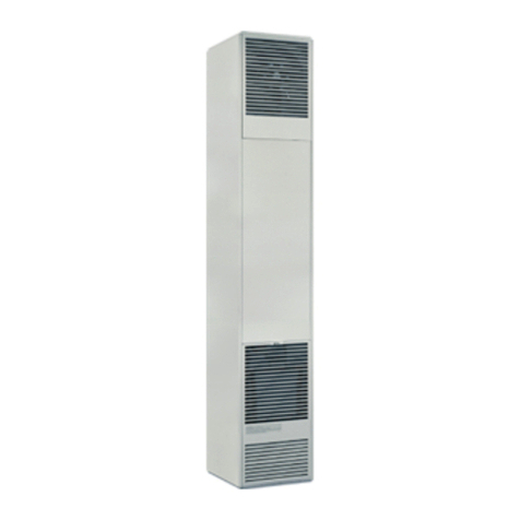
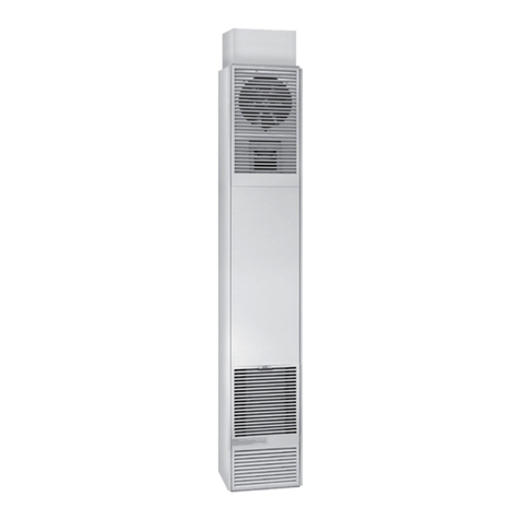
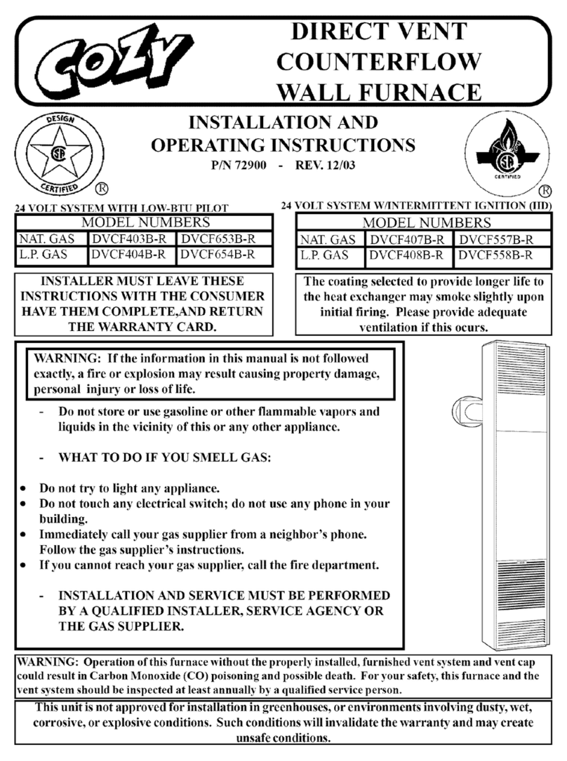
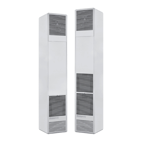
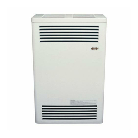
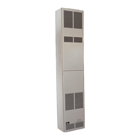
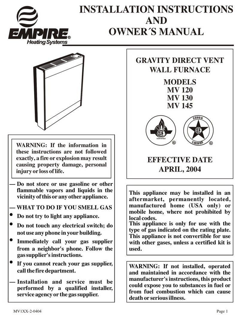
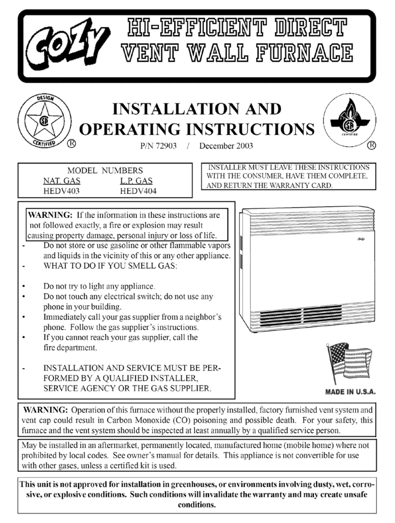
COZY CDV155DPPD User manual

1019068-CPage 1
DIRECT VENT
WALL FURNACE WITH
PILOT PRO
Installation and Operating Instructions
CDV155DPPD
CDV255DPPD
CDV305DPPD
- The coating selected to provide longer life to
the heat exchanger may smoke slightly upon
initial ring.Provide adequate ventilation if
this occurs.
- Installation, maintenance, service,
troubleshooting & repairs must be performed
by a qualied service agency. DO NOT attempt
any of these procedures if you are not qualied
as this could expose you to property damage,
personal injury, or loss of life and will invalidate
all warranties.
- This unit is for residential use only and is not
approved for installation in greenhouses, or
environments involving dusty, wet, corrosive,
or explosive conditions. Such conditions will
invalidate the warranty and may create unsafe
conditions.
Natural Gas - CDV155DPPD, CDV255DPPD & CDV305DPPD
— Do not store or use gasoline or other ammable
vapors and liquids in the vicinity of this or any
other appliance.
— WHAT TO DO IF YOU SMELL GAS
• Do not try to light any appliance.
• Do not touch any electrical switch; do not use
any phone in your building.
• Immediately call your gas supplier from a
neighbor’s phone. Follow the gas supplier’s
instructions.
• If you cannot reach your gas supplier, call the
re department.
— Installation and service must be performed by
a qualied installer, service agency or the gas
supplier.
!WARNING: If the information in these
instructions is not followed exactly, a re or
explosion may result causing property damage,
personal injury or loss of life.
INSTALLER: Leave this manual with the appliance.
CONSUMER: Retain this manual for future reference.
Cozy Heating Systems, LLC | cozyheaters.com | 888-444-1212 | 250 West Laurel Street | Colton, CA 92324
The appliance may be installed in an aftermarket permanently located, manufactured home (USA only) or mobile home,
where not prohibited by local codes. This appliance is only for use with the type of gas indicated on the rating plate. This
appliance is not convertible for use with other gases, unless a certied kit is used.
WARNING:
This product can expose you to chemicals including epichlorohydrin
which is known to the State of California to cause cancer and birth defects and/or
other reproductive harm. For information go to www.p65warnings.ca.gov.
!
WARNING: Improper installation, adjustment
,
alteration, service or maintenance can cause
injury or property damage. Refer to this manual
for proper installation. For assistance or for
additional information consult a qualied installer,
service agency or the gas
supplier.
!

Page 2 1019068-C
Before Installation
Standards ........................................... 2
Specications ..................................... 3
Introduction ........................................ 3
Safety ............................................. 3 -4
Venting ............................................... 4
Clearances .................................... 5 -6
Installation
Special Precautions & Location .......... 6
Installation Steps .......................... 7 -27
Lighting Instructions .......................... 28
Maintenance
Pilot Adjustment ................................ 29
Burner Orice & Orice Chart ........... 30
Thermostat Installation ..................... 30
Removing Burner .............................. 31
Installations In The State Of
Massachusetts .................................. 31
Troubleshooting Chart ...................... 32
DVB-3 Blower Installation ............... 34 -35
BBSK Installation ................................. 36
BBSK Lighting Instructions ................... 37
Parts
CDV155 ..................................... 38 -39
CDV255 & CDV305 .................... 40 -41
Pilot Pro (all models) ...................... 42 -43
Warranty ............................................. 44
CONTENTS
The State of Massachusetts requires that installation
and service of a gas appliance be performed by a
plumber or gas tter licensed in the Commonwealth of
Massachusetts. See page 31.
These installation instructions are a general guide and do not
supersede applicable local codes and ordinances. Before planning
or making the installation be sure it complies with all phases of the
local heating code. (Or, in the absence of local codes, with the latest
edition of National Fuel Gas Code, ANSI.Z223.1, or CAN1-B149).
The appliance, when installed, must be electrically grounded in
accordance with local codes, or in the absence of local codes, with
the latest edition of National Electrical Code ANSI / NFPA 70, or
Canadian Electrical Code CSA-C22.1.
All of the ANSI and NFPA standards referred to in these installation
instructions are the ones that were applicable at the time the design
of this appliance was certified.
The design of this appliance was certified to comply with the latest
edition of ANSI Z21.86 and CSA 2.32.
Installer must leave these instructions with the consumer, have
them complete, and return the warranty card.
READ CAREFULLY BEFORE INSTALLING UNIT
NFPA Standards:
NATIONAL FIRE PROTECTION
ASSOCIATION
1 Batterymarch Park
Quincy, Massachusetts | USA 02169-7471
ANSI & Canadian Standards:
CSA GROUP
178 Rexdale Boulevard,
Toronto, Ontario | Canada M9W 1R3

1019068-CPage 3
Your Direct Vent Wall Furnace is shipped complete in one carton. This carton contains the furnace, vent cap, vent tube, air
inlet tube, template with rough-in dimensions, installation and operating instructions, and the thermostat with thermostat wire.
SPECIFICATIONS & DIMENSIONS
MODEL NUMBERS CDV155DPPD CDV255DPPD CDV305DPPD
Gas Type Natural Natural Natural
Height 29-3/4” 31-3/4” 31-3/4”
Width 21-1/2” 38” 38”
Depth 9-3/4” 9-3/4” 9-3/4”
Input (BTU / HR) 15,000 25,000 30,000
Gas Inlet 1/2” 1/2” 1/2”
Vent Size / Wall Opening 9” 9” 9”
Minimum - Maximum Wall Thickness 5” - 24” 5” - 24” 5” - 15”
Approximate Shipping Weight 66 lbs 100 lbs 100 lbs
Optional Blower Model DVB3 DVB3 DVB3
NOTE: There will be two cartons if an optional vent kit or blower is purchased.
THIS IS A GAS-FIRED, DIRECT VENT WALL FURNACE THAT WILL OPERATE SAFELY AND PROVIDE AN EFFICIENT
SOURCE OF HEAT WHEN INSTALLED, OPERATED AND MAINTAINED AS RECOMMENDED IN THESE INSTALLATION
AND OPERATING INSTRUCTIONS. READ THESE INSTRUCTIONS THOROUGHLY BEFORE INSTALLING, SERVICING,
OR USING THE APPLIANCE. IF YOU DO NOT UNDERSTAND ANY PART OF THESE INSTRUCTIONS CONSULT
LOCAL AUTHORITIES, OTHER QUALIFIED INSTALLERS, SERVICE TECHNICIAN, THE GAS SUPPLIER OR THE
MANUFACTURER.
INTRODUCTION
SAFETY
1. Improper installation, adjustment, alteration, service, or
maintenance can cause property damage, bodily injury
or death.
2. Use in anything other than a residential application may
result in unsatisfactory performance and may void the
warranty.
3. This appliance must be installed in accordance with local
codes, if any; if not, follow the National Fuel Gas Code
ANSI Z223.1/NFPA 54 or the National Gas and Propane
Installation Code CSA-B149.1.
4. Do not install this wall furnace in a recreational vehicle or
trailer.
5. Do not operate wall furnace unless it is connected to the
factory supplied vent system with vent cap in place.
6. Check the rating label attached to the wall furnace to be
sure it is equipped for the type gas you intend to use.
7. Never use a match, candle, ame or other source of
ignition to check for gas leaks. Use only soapy water or
liquid detergent.
8. Have your wall furnace and vent system inspected at
least annually by a qualied service technician.
9. Before cleaning or servicing, turn o the gas and allow
furnace to cool.
10. Do not operate wall furnace without outer casing in place.
11. Due to high temperatures, the wall furnace should be
located out of trac and away from furniture and drapes.
12. Children and adults should be alerted to the hazard of
high surface temperature and should be kept away to
avoid burns or clothing ignition.
13. Young children should be carefully supervised when they
are in the same room with the wall furnace.
14. Do not place clothing or other ammable material on/
near the furnace.
15. Installation and repair should be done by a qualied
service technician. The wall furnace should be inspected
before use and at least annually by a professional service
technician. More frequent cleaning may be required due
to excessive lint from carpeting, bedding material, etc.

Page 4 1019068-C
SAFETY - Continued
VENTING
1) Seal any unused openings in the venting system.
2) Inspect the venting system for proper size and horizontal
pitch, as required in the National Fuel Gas Code, ANSI
Z223.1/NFPA 54 or the Natural Gas and Propane Installation
Code, CSA B149.1 and these instructions. Determine that
there is no blockage or restriction, leakage, corrosion and
other deciencies which could cause an unsafe condition.
3) As far as practical, close all building doors and windows
and all doors between the space in which the appliance(s)
connected to the venting system are located and other
spaces of the building.
4) Close replace dampers.
5) Turn on clothes dryers and any appliance not connected
to the venting system. Turn on any exhaust fans, such as
range hoods and bathroom exhausts, so they are operating
at maximum speed. Do not operate a summer exhaust fan.
6) Follow the lighting instructions. Place the appliance
being inspected into operation. Adjust the thermostat so
appliance is operating continuously.
7) Test for spillage from draft hood equipped appliances at
the draft hood relief opening after 5 minutes of main burner
operation. Use the ame of a match or candle.
8) If improper venting is observed during any of the above
tests, the venting system must be corrected in accordance
with the National Fuel Gas Code, ANSI Z223.1/NFPA 54
and/or Natural Gas and Propane Installation Code, CSA
B149.1.
9) After it has been determined that each appliance
connected to the venting system properly vents when
tested as outlined above, return doors, windows, exhaust
fans, replace dampers and any other gas-red burning
appliance to their previous conditions of use.
!WARNING: CARBON MONOXIDE POISONING HAZARD
Failure to follow the steps outlined below for each appliance connected to the venting system being placed into
operation could result in carbon monoxide poisoning or death.
The following steps shall be followed for each appliance connected to the venting system being placed into operation,
while all other appliances connected to the venting system are not in operation:
It is imperative that control compartments, burner, and
circulating air passageways of the furnace be kept clean.
16. Do not install in a closet, alcove, or small hallway where
the furnace could be isolated from the space to be heated
by closing a door.
17. Do not put anything around the furnace or vent cap that
will obstruct the ow of combustion and ventilation air.
18. The appliance, when installed, must be electrically
grounded in accordance with local codes or, in the
absence of local codes, with the latest edition of National
Electrical Code, ANSI/NFPA 70. In Canada, use CSA
C22.1 Canadian Electrical Code.
19. Never operate this furnace without the sight glass in
place or with the glass broken or missing.
20. If it is suspected that rising water may enter the furnace,
turn o the gas immediately. Do not use this appliance
if any part has been under water. Immediately call a
qualied service technician to inspect the appliance and
to replace any part of the control system and any gas
control which has been under water.
21. It is necessary to replace damaged gaskets or sealing
material within the vent or air intake system. Failure to do
so may result in property damage, personal injury or loss
of life.
22. Any safety screen or guard removed for servicing must
be replaced prior to operating heater.
23. A gas appliance must not be connected to a chimney ue
serving a separate solid-fuel burning appliance.

1019068-CPage 5
CLEARANCES
E
D
B
FIXED
CLOSED FIXED
CLOSED
OPERABLE
C
H
B
B
B
B
F
B
AJ
I
M
K
OPERABLE
Clearance in accordance
with local installation codes &
requirements of the gas supplier
A Clearance above grade, veranda, porch, deck, or balcony
E Clearance to unventilated sot
C Clearance to permanently closed window
G Clearance to inside corner
I Clearance to service regulator vent outlet
B Clearance to window or door that may be opened
F Clearance to outside corner
J Clearance to nonmechanical air supply inlet to building or
the combustion air inlet to any other appliance
K Clearance to a mechanical air supply inlet
H Clearance to each side of center line extended above
meter/regulator assembly
M Clearance under veranda, porch, deck, or balcony
D Vertical clearance to ventilated sot located above the
terminal within a horizontal distance of 2 Feet (61 cm)
from the center line of the terminal
L Clearance above paved sidewalk or paved driveway
located on public property
12 Inches (30 cm)
18 Inches (46 cm)
12 Inches (30 cm)
12 Inches (30 cm)
3 Feet (91 cm)
12 Inches (30 cm)
12 Inches (30 cm)
12 Inches (30 cm)
6 Feet (1.83 m)
3 Feet (91 cm) within a height
15 Feet (4.5m) above the meter /
regulator assembly
12 Inches (30 cm)
Permitted only if veranda, porch,
deck, or balcony is fully open on a
minimum of two sides
18 Inches (46 cm)
7 Feet (2.13m)
A vent shall not terminate directly
above a sidewalk or paved driveway
that is located between two single
family dwellings & serves both dwellings
12 Inches (30 cm)
18 Inches (46 cm)
9 Inches (23 cm)
12 Inches (30 cm)
9 Inches (23 cm)
12 Inches (30 cm)
12 Inches (30 cm)
3 Feet (91 cm) above if within
10 Feet (3 m) horizontally
Clearance in accordance
with local installation codes &
requirements of the gas supplier
18 Inches (46 cm)
REFERENCE LETTER TO DRAWING
CANADIAN
INSTALLATIONS* U.S. INSTALLATIONS**
G
A
Inside
Corner
Detail
*In accordance with the current CSA-B149.1
Natural Gas and Propane Installation Code
**In aaccordance with the current ANSI
Z223.1 / NFPA 54 National Fuel Gas Code
= Air Supply Inlet
= Vent Terminal
= Area where terminal is
not permitted

Page 6 1019068-C
CLEARANCES - Continued
1. If the wall furnace is installed directly on carpeting, tile or any combustible material other than wood ooring, the wall furnace
shall be installed on a metal plate or wood panel secured to the oor, extending the full width and depth of the wall furnace.
2. RESIDENTIAL GARAGE INSTALLATION:
Gas utilization equipment in residential garages shall be installed so that all burners and burner ignition devices are located
not less than 18 inches (46cm) above the oor. Such equipment shall be located, or protected so it is not subject to damage
by a moving vehicle. Use care in selecting a good location within the garage.
• DO NOT locate the appliance where heated air will be directed onto a nearby parked vehicle.
• Paint may discolor or rubber may harden and crack.
• DO NOT allow heated discharge air to blow directly onto open or closed containers of paint, gasoline
or other liquids having ammable vapors.
SPECIAL PRECAUTIONS
Due to high temperatures the appliance should be located out of
trac and away from furniture and draperies.
Children and adults should be alerted to the hazards of high surface
temperature and should stay away to avoid burns or clothing ignition.
Young children should be carefully supervised when they are in the
same room as the appliance.
Clothing or other ammable material should not be placed on or near
the appliance.
Any safety screen, guard, or casing top removed for servicing a room
heater must be replaced prior to operating the appliance.
Do not use this heater if any part has been under water. Immediately
call a qualied service technician to inspect the heater and to replace
any part of the control system and any gas control which has been
under water.
LOCATION
1) The wall furnace must be
installed on an outside wall.
2) For optimal heat distribution,
locate furnace as centrally as
possible in the area to be heated
and where occupants may move
about freely without coming into
contact with the grille.
3) If the furnace is installed in a
basement, a 12” clearance must
be maintained between ground
level and the bottom of the vent
cap. Do not install furnace where
vent cap will terminate in a
window well or any other opening
below ground level.
ALL VENT CAPS
FIG. 3
9”
Min.
12”
Min.
18” Minimum
12” Minimum
FIG. 2
CDV25-D / CDV30-DCDV15-D
FIG. 1
Left Side Wall
Ceiling
1”
24”
1/2” Floor
Right Side Wall
1”
Left Side Wall
Ceiling
Floor
0”
1”
4”
30”
Right Side Wall

1019068-CPage 7
INSTALLATION
!WARNING: Failure to follow these instructions carefully could result in
poor performance, property damage, personal injury or death.
STEP 1. LOCATE VENT OPENING
Locate wall studs and center 9” vent opening a minimum of 22” for CDV15 or 24-1/8” for CDV25/30 above
the oor. To locate furnace at minimum clearance from oor, remove template from carton and set on oor
at location desired.
For model CDV15:
Position template no closer
than 1” from either side wall.
For model CDV25/30:
Position template 1” minimum from a
left side wall or 0” from a right side wall.
Check outside wall to be sure there is proper clearances around the vent cap. See Figure 3. Next, mark
and cut out the vent openings on both the inside and outside walls (be sure to keep the holes level). See
Figure 5. If a higher location on the wall is desired, raise bottom of template to desired height, make sure
template is level and centered between studs, mark and cut out vent openings.
STEP 2. ROUGH-IN GAS SUPPLY
Install a ½” diameter gas supply line. This line can enter through the oor, side, or rear wall. For location
of gas connection to valve, See Figure 4. The gas supply line must have an individual manual shut o
valve located outside the cabinet, accessible from the room where the heater is installed. Install a drip leg
immediately ahead of the gas valve and provide a 1/8” N.P.T. plugged tapping, accessible for test gauge
connection, immediately upstream of the gas supply connection. The furnace and the individual shut o
valve must be disconnected from the gas supply piping system during any pressure testing of that system
at test pressures in excess of 1/2” psig (3.5kPa). The furnace must be isolated from the gas supply piping
system by closing the individual manual shut o valve during any pressure testing of the gas piping system
at test pressures equal to or less than 1/2” psig (3.5kPa).
STEP 3-A. INSTALLING FURNACE ON STANDARD WALLS (5” - 9”)
Use only the exhaust tube, air intake tube, wall thimble extension, and vent terminal provided with furnace.
Do not attempt to lengthen the exhaust or air intake tubes, this could cause an imbalance in the furnace
resulting in poor performance and pilot outage, see Figure 6.
Extend the telescoping wall thimble extension (surrounding the wall thimble assembly) to approximately
9 inches. Center the wall thimble assembly in the 9-inch opening and attach to inside wall using eight (8)
screws. The wall thimble extension should extend through the opening and be adjusted so end of wall
thimble extension is even with outside wall. Install furnace ush to wall by sliding exhaust tube and air
intake tube through the wall thimble assembly. Secure the furnace to the wall with screws through each of
the four holes in the mounting brackets located on the back of the furnace. These holes are spaced so as
to allow the screws to enter into studs that are on 16-inch centers. On certain types of wall, anchors (not
provided) may be required.
Slide the vent terminal onto the exhaust tube and the air intake tube. Secure vent terminal and vent
terminal spacer plate to wall providing a slight downward slope to the vent tubes. This will prevent water
from entering. Anchors (not provided) may be required. Caulk around vent terminal spacer plate with putty
provided. See Figure 7.
NOTE: Some framing may be necessary to provide a at surface for the vent terminal spacer plate to butt
against, so rain cannot enter through cut out.

Page 8 1019068-C
INSTALLATION FOR ALTERNATE WALL DIMENSIONS
9” TO 15" WALLS
( CDV15 / CDV25-D )
For 9" to 15" wall use Vent Kit No.
VK1525/9-15-B. Do not attempt to
lengthen the exhaust tube, air intake tube,
or wall thimble extension provided with
furnace or the VK1525/9-15-B Vent Kit.
Disconnect the air intake tube, and the
exhaust tube from the back of the furnace
and discard. See Figure 6. Replace with
exhaust tube and air intake tube from Kit
No. VK1525/9-15-B.
Discard the 5" telescoping wall thimble
extension that surrounds the wall thimble
assembly. Center the wall thimble
assembly in the 9" opening and attach to
inside wall using eight (8) screws. Install
furnace ush to wall by sliding exhaust
tube and air intake tube through the wall
thimble assembly. Secure the furnace
to the wall with screws through each of
the four holes in the mounting brackets
located on the back of the furnace. These
holes are spaced so as to allow the screws
to enter into studs that are on 16-inch
centers. On certain types of wall, anchors
(not provided) may be required.
From outside the building install the thick
wall thimble extension, Part No. 43835,
supplied in Vent Kit No. VK1525/9-15-B by
sliding it through the cut out and over the
wall thimble assembly. The wall thimble
extension should be even with the outside
wall (some trimming may be necessary).
Slide the vent terminal onto the exhaust
tube and the air intake tube. Secure vent
terminal and vent terminal spacer plate
to wall providing a slight downward slope
to the vent tubes. This will prevent water
from entering. Anchors (not provided)
may be required. Caulk around the vent
terminal spacer plate with putty provided.
See Figure 7.
NOTE: Some framing may be necessary to
provide a at surface for the vent terminal
spacer plate to butt against, so rain cannot
enter through cut out.
15” TO 24” WALLS
( CDV15 / CDV25-D )
For 15" to 24" wall use only Vent Kit
No. VK1525/15-24-B. Do not attempt to
lengthen the exhaust tube, air intake tube,
or wall thimble extension provided with
furnace. The VK1525/15-24-B Vent Kit has
a one inch restrictor in the exhaust tube
which is necessary for proper and safe
operation of this furnace. Do not use any
other vent kit. Disconnect the air intake
tube and the exhaust tube from the back
of the furnace and discard, see Figure 6.
Install the exhaust tube and air intake tube
from Vent Kit No. VK1525/15-24-B.
Discard the 5" telescoping wall thimble
extension that surrounds the wall thimble
assembly. Center the wall thimble
assembly in the 9" opening and attach to
inside wall using eight (8) screws. Install
furnace ush to wall by sliding exhaust
tube and air intake tube through the wall
thimble assembly. Secure the furnace
to the wall with screws through each of
the four holes in the mounting brackets
located on the back of the furnace. These
holes are spaced so as to allow the screws
to enter into studs that are on 16-inch
centers. On certain types of walls, anchors
(not provided) may be required.
From outside the building install the
wall thimble extension, Part No. 43730,
supplied in Vent Kit No. VK1525/15-24-B
by sliding it through the cut out and over
the wall thimble extension. For walls
15" to 19" the wall thimble extension, air
intake tube, and the exhaust tube must be
trimmed even with the outside wall. Slide
the vent terminal onto the exhaust tube
and into the air intake tube. Secure vent
terminal and vent terminal spacer plate
to wall providing a slight downward slope
to the vent tubes. This will prevent water
from entering. Anchors (not provided)
may be required. Caulk around the vent
terminal spacer plate with putty provided,
See Figure 7.
NOTE: Some framing may be necessary to
provide a at surface for the vent terminal
spacer plate to butt against, so rain cannot
enter through the cut out.
9” TO 15” WALLS
( CDV30-D )
For 9” to 15” wall use Vent Kit No. VK30/9-
15. Do not attempt to lengthen the exhaust
tube, air intake tube, or wall thimble
extension provided with furnace or the
VK30/9-15 Vent Kit. Disconnect the air
intake tube, and the exhaust tube from
the back of the furnace and discard. See
Figure 6. Replace with exhaust tube and
air intake tube from Kit No. VK30/9-15.
Discard the 5” telescoping wall thimble
extension that surrounds the wall thimble
assembly. Center the wall thimble assembly
in the 9” opening and attach to inside wall
using eight (8) screws. Install furnace
ush to wall by sliding exhaust tube and
air intake tube through the wall thimble
assembly. Secure the furnace to the wall
with screws through each of the four holes
in the mounting brackets located on the
back of the furnace. These holes are
spaced so as to allow the screws to enter
into studs that are on 16-inch centers.
On certain types of walls, anchors (not
provided) may be required.
From outside the building install the thick
wall thimble extension, Part No. 43835,
supplied in Vent Kit No. VK30/9-15 by
sliding it through the cut out and over the
wall thimble assembly. The wall thimble
extension should be even with the outside
wall (some trimming may be necessary).
Slide the vent terminal onto the exhaust
tube and the air intake tube. Secure vent
terminal and vent terminal spacer plate
to wall providing a slight downward slope
to the vent tubes. This will prevent water
from entering. Anchors (not provided)
may be required. Caulk around the vent
terminal spacer plate with putty provided.
See Figure 7.
NOTE: Some framing may be necessary to
provide a at surface for the vent terminal
spacer plate to butt against, so rain cannot
enter through cut out.

1019068-CPage 9
INSTALLATION
FIG. 5 CDV15-D CDV25/30-D
FIG. 4 CDV15-D CDV25/30-D
9” Dia.
Opening
22"
8"
9"
18"
1/2" Floor
1/8” N.P.T.
Pressure Tap
Gas Supply
Gas
Valve
Inlet
1/2" Black Iron Pipe
Drip Leg
Shut O Valve
1/2” Min. Center
Line Pipe Elbow
29-3/4"
Cabinet 34-1/2" Cabinet
Shut O Valve
9" Dia.
Opening
Gas
Valve
Inlet
16-5/8"13-3/8"
31-3/4"
13”
4”
24-1/8"
Drip Leg
1/2” Black
Iron Pipe
Gas
Supply
Floor
FIG. 6 CDV15-D CDV25/30-D
1” Minimum Both Sides
Wall Studs
16” O.C.
Template
Mounting
Holes
1” Minimum Both Sides
Wall Studs 16” O.C.
Template
Mounting
Holes
Exhaust Tube
Exhaust Tube
Air Intake
Tube
Air Intake
Tube

Page 10 1019068-C
INSTALLATION
FIG. 7
Vent Terminal Spacer Plate
Outside Wall
Wall Thimble
Extension
Wall Thimble Assembly
Wall Stud Inside Wall
Vent
Terminal
If the outlet pressure of the gas valve must be adjusted, this
must be done by a qualied service technician using proper tools
and instruments.
Check all connections with soapy water for possible gas leaks. Never
use a match, candle or other ignition source. It is recommended
that pipe compound which is resistant to the action of liqueed
petroleum gases be used. Do not use Teon tape or Teon impreg-
nated compound.
The appliance and its individual shuto valve must be disconnected
from the gas supply piping during any pressure testing of that
system at test pressure in excess of ½ psig.
The appliance must be isolated from the gas supply piping by
closing its individual manual shuto valve during any pressure
testing of the gas supply piping system at test pressures equal to
or less than ½ psig.
The gas supply piping should be sized in accordance
with ANSI Z223.1 National Fuel Gas Code.
7” w.c.
3.5” w.c.
Natural Gas
4.5” w.c.
Maximum Inlet Pressure
(Must NEVER Exceed):
Normal Manifold Pressure:
(Pre-set at the factory)
GAS SUPPLY PIPE
Minimum Inlet Pressure
(For purpose of input adjustment):
This heater must be connected to a gas supply capable of supplying the full rated capacity. Provide a 1/8 inch N.P.T. plugged
tapping, accessible for test gauge connection, immediately upstream of the gas supply connection to the appliance.
STEP 3-B. GAS CONNECTION
FIG. 8
For the CDV15,
CDV25 and CDV30
TO HEATER
GAS CONTROL
VALVE
MANUAL CUT-OFF VALVE
DRIP
LEG
1/8” NPT
PRESSURE TAP
GAS
SUPPLY
LINE

1019068-CPage 11
INSTALLATION
STEP 4.
The next few steps
will vary depending on
the model of CDV you are
assembling.
For the smaller
155 model:
CDV155DPPD
Continue to page 12.
NOTE: Pages 12-14 are assembly
steps specically for the CDV155DPPD
(this section has a gray background).
NOTE: Pages 15-17 are assembly
steps specically for the CDV255DPPD
and CDV305DPPD models.
For the larger,
255 / 305 models:
CDV255DPPD
OR CDV305DPPD
Skip ahead to page 15.

Page 12 1019068-C
INSTALLATION (CDV155DPPD)
TH
TP
THTP
ADJ
PILOT
IN
34
green
wire
orange
wire
black
wire
46
47
33
STEP 5-A.
Connecting the PilotPro Wires
Find the three connection terminals at the
base of the heater IID Valve (34).
Find the green,
orange and black
wires that are
together on one
end of the Wiring
Harness (57).
Connect:
- Green TH wire to TH terminal of the valve.
- Black TP wire to the TP terminal of valve.
- Orange THTP wire to the THTP terminal of
the valve.
NOTE: Ensure that all of the
connections are tightened firmly.
57
47 33
STEP 5-B.
On the inside of the CDV, locate
the Flame Sensor (46) and Ignitor (32).
Plug the Flame
Sensor (46) into one
end of the Flame
Sensor Wire (47).
Plug the Orange
Ignitor Wire (33) into
the Ignitor (32).
32

1019068-CPage 13
INSTALLATION (CDV155DPPD)
STEP 5-D.
The wires from Steps 5-B
and 5-C should appear as
illustrated here.
Find cable ties (64) within the
hardware bag to be used on
step 6.
Choose which side of your heater will best accomodate the PilotPro attachment.
• It can be installed on your choice of the left OR right side.
• Be sure to allow room for future removal of the PilotPro cover.
• Do not install the PilotPro more than 10” from the base of the heater.
≤10” ≤10”
Right Side
Install
Left Side
Install
STEP 5-C.

Page 14 1019068-C
INSTALLATION (CDV155DPPD)
NOTE IF USING BLOWER KIT DVB3:
Attach the wires to the Blower Shield
B
OR:
STEP 6.
Right Side Install
Left Side Install
A. Bundle and loop the
wires, neatly settling them
on the valve bracket.
B. Allow the free ends
of the wires to extend to
the RIGHT, approximately
16” from the rear of the
valve bracket.
C. Bundle and secure the
wires to each end of
the valve bracket with
two cable ties (64) as
illustrated.
WARNING:
Ensure wires
do not touch
combustion
chamber.
WARNING:
Ensure wires
do not touch
combustion
chamber.
A. Bundle and loop the
wires, neatly settling them
on the valve bracket.
B. Allow the free ends
of the wires to extend to
the LEFT, approximately
16” from the rear of the
valve bracket.
C. Bundle and secure the
wires to each end of
the valve bracket with
two cable ties (64) as
illustrated.
SKIP TO STEP 7 ( PAGE 18 )
A
C
16”
B
A
C
16”

1019068-CPage 15
47
INSTALLATION (CDV255DPPD and CDV305DPPD)
TH
TP
THTP
ADJ
PILOT
IN
green
wire
orange
wire
black
wire
STEP 5-A.
Connecting the PilotPro Wires
Find the three connection terminals at the
base of the heater IID Valve (34).
Find the green,
orange and black
wires that are
together on one
end of the Wiring
Harness (57).
- Connect Orange THTP wire to the THTP
terminal of the valve.
- Connect Black TP wire to the TP terminal of valve.
- Connect Green TH wire to TH terminal of
the valve.
NOTE: Ensure that all of the
connections are tightened firmly.
34
57
STEP 5-B.
On the inside of the CDV, locate the Flame
Sensor (46) and Ingitor (32).
Plug the Flame Sensor
(46) into one end of
the Flame Sensor
Wire (47).
Plug the Orange
Ignitor Wire (33) into
the Ignitor (32). 32
46
47
33
33

Page 16 1019068-C
INSTALLATION (CDV255DPPD and CDV305DPPD)
STEP 5-D.
The wires from Steps 5-A
and 5-B should appear as
illustrated here.
Find cable ties (64) within the
hardware bag to be used on
step 6.
Choose which side of your heater will best accommodate the PilotPro attachment.
• It can be installed on your choice of the left OR right side.
• Be sure to allow room for future removal of the PilotPro cover.
• Do not install the PilotPro more than 10” from the base of the heater.
≤10” ≤10”
Right Side
Install
Left Side
Install
STEP 5-C.

1019068-CPage 17
NOTE: If using Blower Kit DVB3 -
Attach the wires to the Blower Shield.
B
C
A
A
B
OR:
STEP 6.
Right Side Install
Left Side Install
A. Connect the orange
sparker wire and
black sensor wire to
the lower heat shield
with a cable tie (64)
directly below the
burner sight glass.
A. Bundle wires
together and
pull toward the
left side of
the unit.
B. Route the orange
and black wires over
to the wiring harness
(connected to the
valve).
B. Allow the free ends of wires to
extend approximately 16” from
the edge of the heat shield.
Connect the wires to the left
side of the lower heat shield with
a cable tie (64).
C. Allow the free ends of
the wires extend approx-
imately 6” from the rear
of the valve bracket.
Bundle and secure the
wires to the valve bracket
with two cable ties (64)
as illustrated.
C. Secure the
hanging wires to
lower heat shield
(directly below
burner sight glass)
with a cable tie (64).
6”
16”
C
INSTALLATION (CDV255DPPD and CDV305DPPD)
WARNING:
Ensure wires
do not touch
combustion
chamber.
WARNING:
Ensure wires
do not touch
combustion
chamber.

Page 18 1019068-C
WARNING: Add the wiring sleeves on this step to prevent PilotPro damage during testing.
INSTALLATION
Black
Black
Orange
Red
Brown
Green
50
57
STEP 7.
Plug main Wiring Harness (57) into the
Control Module (50).
NOTE: Plug the wiring harness into
place with the clip facing out as
illustrated here.
STEP 8.
Add the protective Wire Sleeves (63)
to both wires that extend from the Battery
Pack (49) and slide back the clear
insulation on both wires.
Connect the red wire from the Battery
Pack (49) and the red wire from the Wiring
Harness (57). Slide the Electrical Sleeve (63)
over the connection.
Connect the black wire
from the Battery Pack (49) to
the black wire from the Wiring
Harness (57).
Slide the Electrical Sleeve (63)
over the connection.
Red
Wire
Red
Wire
49 57
63
Black
Wire
49 57
Black Wire
63

1019068-CPage 19
INSTALLATION
STEP 10-A.
Plug the orange wire (33) from
Ignitor (32) into the port labeled
“I” on the control module (50).
NOTE: Ensure it is rmly
seated.
SWI
SWI
B
a
r
e
B
r
o
w
n
W
i
r
e
B
a
r
e
B
r
o
w
n
W
i
r
e
A
B
White Wire
(Thermostat)
Red Wire
(Thermostat)
57
STEP 9.
A. Connect bare brown
SWI wire from the
control module wiring
harness (57) to the white
thermostat wire, using a
wire nut.
B. Connect the bare
brown wire from the
control module wiring
harness (57) to the red
thermostat wire, using a
wire nut.
A
B
33
50
I
33
32

Page 20 1019068-C
INSTALLATION
STEP 10-B.
Plug the black ame sensor
wire (47) into the port labeled “S” on
the control module (50). Ensure it is
rmly seated.
47
NOTE: Base of
the connector
terminal may be
slightly exposed.
STEP 10-C.
S
50
47
ENSURE THE WIRING IS DONE
ACCORDING TO THIS DIAGRAM
This manual suits for next models
2
Table of contents
Languages:
Other COZY Wall Furnace manuals

COZY
COZY CDV335C User manual

COZY
COZY DVCF403C-H User manual

COZY
COZY CF553D-H User manual

COZY
COZY CDV155B and User manual

COZY
COZY HEDV253A and User manual

COZY
COZY DVCF403C-H User manual

COZY
COZY W255G User manual

COZY
COZY CDV155B and User manual

COZY
COZY DVCF40 User manual

COZY
COZY DVCF653B-H and User manual