COZY W255G User manual

GAS-FIRED VENTED
WALL FURNACE
Installation and Operating Instructions
ENGLISH
Click here for the full manual or
click on the links below to quickly
locate what you’re looking for:
ESPAÑOL
Haga clic aquí para ver el manual
completo o haga clic en los
siguientes enlaces para localizar
rápidamente lo que está buscando:
FRANÇAIS
Cliquez ici pour le manuel complet
ou cliquez sur les liens ci-dessous
pour localiser rapidement ce que
vous recherchez:
1017754-A_webcvr
Antes de la Instalación
Las Normas ......................................... 2
Especicaciones .................................. 3
Introducción ........................................ 4
Normas de Seguridad .......................... 4
Espacios Libres ................................... 5
Controles y Orices ............................. 5
Aire de Combustion y Ventilacion .... 6 - 8
Instalación
Instrucciones para Instalación ....... 9 - 11
Diagrama de Cableado ...................... 11
Instalación ......................................... 12
Instrucciones para
el Encendido ...................................... 13
Mantenimiento
Instrucciones para el Mantenimiento . 14
Ajuste del Piloto ................................. 14
Ajuste de la Llama de la Hornilla ....... 14
Kit:
Instalación del BBSK ................... 15 -17
Kit del Registro Posterior de
40542-A (Opcional) ...................... 18 -19
Kit del Ventilador de WFF81-C ......... 20
Tabla para la Solución
de Problemas .............................. 21 -23
Dibujos y Lista de los Piezas ...... 24 - 27
Garantia Limitada .............................. 28
Avant L’installation
Normes ................................................ 2
Spécications ...................................... 3
Introduction ......................................... 4
Règles De Sécurité .............................. 4
Dégagements ...................................... 5
Commandes y Orices ........................ 5
Air Combustion et de Ventilation .... 6 - 8
Installation
Instructions D’installation à
L’intérieur du Mur .......................... 9 - 11
Schéma de Câblage .......................... 11
Installation ......................................... 12
Instructions D’allumage ..................... 13
D’entretien
Instructions D’entretien ...................... 14
Réglage de la Veilleuse ..................... 14
Réglage des Flammes du Brûleur ..... 14
Fourniment:
BBSK: Installation....................... 15 - 17
40542-A: (Optionnel)
Kit Post-Registre ......................... 18 - 19
WFF81-C: Kit de Ventilateur ............. 20
Guide de Dépannage ................ 21 - 23
Dessins et Liste de Pièces ......... 24 - 27
Limitation de Garantie ....................... 28
Before Installation
Standards ............................................ 2
Specications ...................................... 3
Introduction ......................................... 4
Safety .................................................. 4
Clearances .......................................... 5
Controls & Orices ............................... 5
Combustion & Venting ..................... 6 - 8
Installation
Rough-In Instructions .................... 9 - 11
Wiring Diagram .................................. 11
Installation ......................................... 12
Lighting Instructions ........................... 13
Maintenance
Maintenance Instructions ................... 14
Pilot Adjustment ................................. 14
Burner ame Adjustment ................... 14
Kits:
BBSK Installation ......................... 15 -17
40542-A
Rear Register Kit ......................... 18 -19
WFF81-C Fan Kit .............................. 20
Troubleshooting Charts ............... 21 -23
GWF Part List .............................. 24 -27
Warranty ............................................ 28

1017754-A
Page 1
GAS-FIRED VENTED
WALL FURNACE
Installation and Operating Instructions
NATURAL GAS - W255G, W355G, W505G, W255G-3, W355G-3, W505G-3, W255G-5,
W355G-5, W505G-5, W255G-7, W355G-7, W505G-7 | PROPANE GAS - W256G, W356G, W506G
— Donotstoreorusegasolineorotherammablevaporsand
liquidsinthevicinityofthisoranyotherappliance.
— WHAT TO DO IF YOU SMELL GAS
•Donottrytolightanyappliance.
•Donottouchanyelectricalswitch;donotuseanyphone
inyourbuilding.
•Immediatelycallyourgassupplierfromaneighbor’sphone.
Followthegassupplier’sinstructions.
•Ifyoucannotreachyourgassupplier,calltheredepartment.
— Installationandservicemustbeperformedbyaqualied
installer,serviceagencyorthegassupplier.
!WARNING:Iftheinformationintheseinstructionsisnot
followedexactly,areorexplosionmayresultcausingproperty
damage,personalinjuryorlossoflife.
INSTALLER:Leavethismanualwiththeappliance.
CONSUMER:Retainthismanualforfuturereference.
The coating selected to provide
longer life to the heat exchanger
may smoke slightly upon initial
ring. Please provide adequate
ventilation if this occurs.
This unit is NOT to be installed
in mobile homes.
Cozy Heating Systems, LLC | cozyheaters.com | 855-589-5380 | 3230 Industrial Pkwy | Jeffersonville, IN 47130
- Installation, maintenance, service, troubleshooting & repairs must be performed by a qualified service agency. DO NOT attempt
any of these procedures if you are not qualified as this could expose you to property damage, personal injury, or loss of life and
will invalidate all warranties.
- This unit is for residential use only and is not approved for installation in mobile homes, greenhouses, or environments involving
dusty, wet, corrosive, or explosive conditions. Such conditions will invalidate the warranty and may create unsafe conditions.
- This appliance is equipped with a blocked flue switch designed to protect against a blocked flue condition.
WARNING: Operation of this furnace without the properly installed, factory furnished vent system & vent cap could result in Carbon
Monoxide (C.O.) poisoning and possible death. For your safety, this furnace & the vent system should be inspected at least annually
by a qualified service technician.

1017754-A
Page 2
BeforeInstallation
Standards ........................................... 2
Specications ..................................... 3
Introduction ........................................ 4
Safety ................................................. 4
Clearances ......................................... 4
Controls & Orices .............................. 4
Combustion & Venting .................... 6 -8
Installation
Rough-In Instructions .................... 9 -11
Wiring Diagram ................................. 11
Installation ........................................ 12
Lighting Instructions .......................... 13
Maintenance
Maintenance Instructions .................. 14
Pilot Adjustment ................................ 14
Burner ame Adjustment ................... 14
Kits:
• BBSK Installation ........................ 15 -17
• 40542-A Rear Register Kit ........... 18 -19
• WFF81-C Fan Kit ............................. 20
Troubleshooting Charts ............... 21 -23
Parts
GWF Part List ............................. 24 -27
Warranty ............................................. 28
CONTENTS
TheStateofMassachusettsrequiresthatinstallation
andserviceofagasappliancebeperformedbya
plumberorgastterlicensedintheCommonwealthof
Massachusetts.
These installation instructions are a general guide and do not
supersede applicable local codes and ordinances. Before planning
or making the installation be sure it complies with all phases of the
local heating code. (Or, in the absence of local codes, with the latest
edition of National Fuel Gas Code, ANSI.Z223.1, or CAN1-B149).
The appliance, when installed, must be electrically grounded in
accordance with local codes, or in the absence of local codes, with
the latest edition of National Electrical Code ANSI / NFPA 70, or
Canadian Electrical Code CSA-C22.1.
All of the ANSI and NFPA standards referred to in these installation
instructions are the ones that were applicable at the time the design
of this appliance was certified.
The design of this appliance was certified to comply with the latest
edition of ANSI Z21.86 and CSA 2.32.
Installer must leave these instructions with the consumer, have
them complete, and return the warranty card.
READ CAREFULLY BEFORE INSTALLING UNIT
NFPA Standards:
NATIONAL FIRE PROTECTION
ASSOCIATION
1 Batterymarch Park
Quincy, Massachusetts | USA 02169-7471
ANSI & Canadian Standards:
CSA GROUP
178 Rexdale Boulevard,
Toronto, Ontario | Canada M9W 1R3

1017754-A
Page 3
Your vented wall furnace comes packed in a single carton. Included in the box: the thermostat, thermostat wire, and
insulated staples. Before installing the wall furnace check the rating plate to verify that the Model Number is correct and
that the wall furnace is equipped for the type gas you intend to use.
SPECIFICATIONS & DIMENSIONS
SINGLE WALL FURNACE
MODEL NUMBERS W255 W355 W256 W356
Gas Type Natural Propane
Type of Control Millivolt Wall Stat. Millivolt Wall Stat
Height 68” h 68” h 68” h 68” h
Width 16.5” w 16.5” w 16.5” w 16.5” w
Depth 6.5” d 6.5” d 6.5” d 6.5” d
Input (BTU / HR) 25,000 35,000 25,000 33,000
Type of Pilot Standing Standing Standing Standing
Vent size 4” 4” 4” 4”
Gas Inlet 1/2” 1/2” 1/2” 1/2”
Approximate Shipping Weight 90lbs 90lbs 90lbs 90lbs
Rear Model Num. 40542 40542 40542 40542
Register Kit Weight 5lbs 5lbs 5lbs 5lbs
Fan Kit Model Num. WFF81 WFF81 WFF81 WFF81
Weight 10 lbs 10 lbs 10 lbs 10 lbs
NOTES:
- If optional rear register kit is to be
used, see supplemental installation
instructions (No. 84504) and section
marked “Special Instructions for Rear
Register Kit Application” prior to
installation of Rough-In.
- This heater may be installed without
recessing into stud space by using
optional FSK (Free Standing Kit).
DUAL WALL FURNACE
MODEL NUMBERS W505 W506
Gas Type Natural Propane
Type of Control Millivolt Wall Stat.
Height 68” h 68” h
Width 16.5” w 16.5” w
Depth 6.5” d 6.5” d
Input (BTU / HR) 50,000 50,000
Type of Pilot Standing Standing
Vent size 4” 4”
Gas Inlet 1/2” 1/2”
Approximate Shipping Weight 134 lbs 134 lbs
Fan Kit Model Num. WFF81 WFF81
Weight 10 lbs 10 lbs

1017754-A
Page 4
THIS IS A GAS-FIRED, GRAVITY VENTED WALL FURNACE THAT WILL OPERATE SAFELY AND PROVIDE AN EFFICIENT
SOURCE OF HEAT WHEN INSTALLED, OPERATED AND MAINTAINED AS RECOMMENDED IN THESE INSTALLATION
AND OPERATING INSTRUCTIONS. READ THESE INSTRUCTIONS THOROUGHLY BEFORE INSTALLING, SERVICING,
OR USING THE APPLIANCE. IF YOU DO NOT UNDERSTAND ANY PART OF THESE INSTRUCTIONS, CONSULT LOCAL
AUTHORITIES, OTHER QUALIFIED INSTALLERS, SERVICE TECHNICIAN, THE GAS SUPPLIER OR THE MANUFACTURER.
1. The wall furnace should be located near the
center of the house for best heat distribution.
2. Due to high temperatures, the appliance should
be located out of trafc and away from furniture
and draperies.
3. Children and adults should be alerted to the
hazards of high surface temperature and should
stay away to avoid burns or clothing ignition.
4. Young children should be carefully supervised
when they are in the same room as the appliance.
5. Do not place clothing or other ammable material
on or near the appliance. Precautions should be
taken so as not to place furniture, drapes, or
other articles directly in front of grille or lower
access door that would obstruct air openings as
proper air ow is critical to proper operation of
unit.
6. Any safety screen guard or casing front removed
for servicing an appliance must be replaced prior
to operating the appliance.
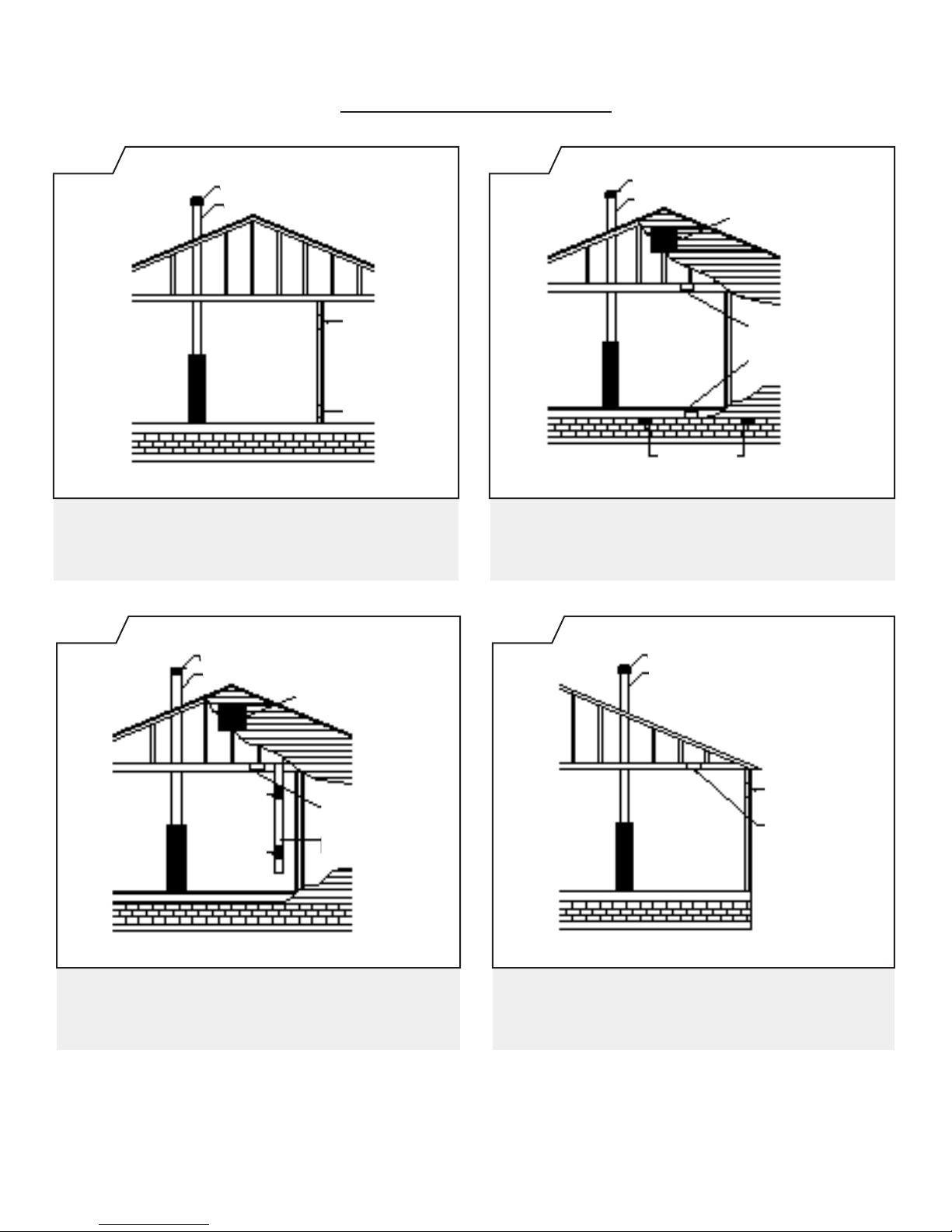
7. Heater must be installed with legs resting on the
2x4 oor sill plate (recessed) or the factory FSK
Kit (ush mount). The header plate shall then
be installed at a height 65-3/4 inches above top
surface of the plate that the heater legs rest on.
This provides the listed 2 inch minimum oor
clearance.
If the area where the heater is installed contains
carpeting, tile, etc., the listed 2 inch minimum
oor clearance must be maintained from the
top surface of these materials. If the heater is
installed DIRECTLY on carpeting, tile or any
combustible material other than wood ooring,
the heater shall be installed on a metal or wood
panel secured to the oor, extending the full
width and depth of the heater.
8. Installation and repair must be done by a
qualied installer or service technician. The wall
furnace must be inspected before use and at
least annually by a qualied service technician.
INTRODUCTION
SAFETY
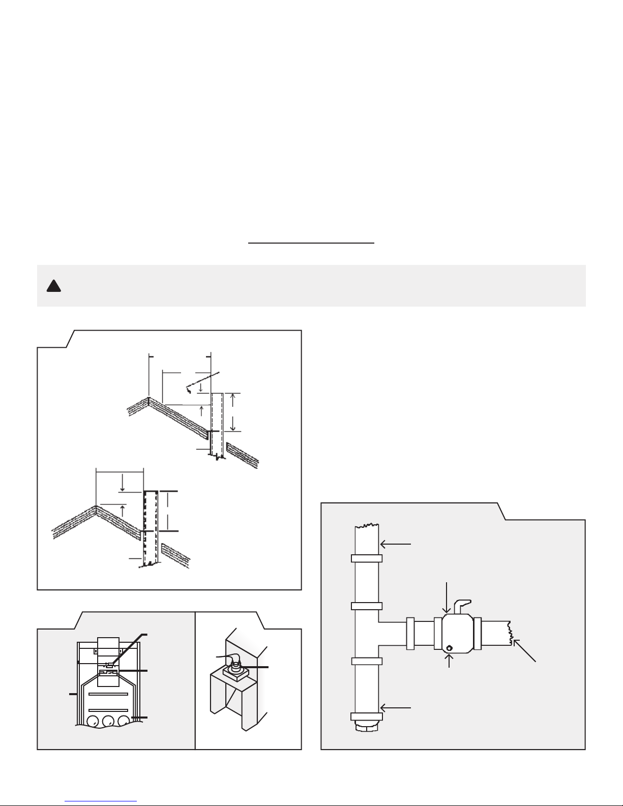
The following steps shall be followed for each appliance
connected to the venting system being placed into operation,
while all other appliances connected to the venting system are
not in operation:
1. Seal any unused openings in the venting system.
2. Inspect the venting system for proper size and horizontal
pitch, as required in the National Fuel Gas Code, ANSI
Z223.1/NFPA 54 or the Natural Gas and Propane Installation
Code, CSA B149.1 and these instructions. Determine that
there is no blockage or restriction, leakage, corrosion and
other deciencies which could cause an unsafe condition.
3. As far as practical, close all building doors and windows
and all doors between the space in which the appliance(s)
connected to the venting system are located and other spaces
of the building.
4. Close replace dampers.
5. Turn on clothes dryers and any appliance not connected to
the venting system. Turn on any exhaust fans, such as range
hoods and bathroom exhausts, so they are operating at
maximum speed. Do not operate a summer exhaust fan.
6. Follow the lighting instructions. Place the appliance being
inspected into operation. Adjust the thermostat so appliance
is operating continuously.
7. Test for spillage from draft hood equipped appliances at
the draft hood relief opening after 5 minutes of main burner
operation. Use the ame of a match or candle.
8. If improper venting is observed during any of the above tests,
the venting system must be corrected in accordance with
the National Fuel Gas Code, ANSI Z223.1/NFPA 54 and/or
Natural Gas and Propane Installation Code, CSA B149.1.
9. After it has been determined that each appliance connected
to the venting system properly vents when tested as outlined
above, return doors, windows, exhaust fans, replace
dampers and any other gas-red burning appliance to their
previous conditions of use.
!WARNING:
CARBON MONOXIDE POISONING HAZARD
Failuretofollowthestepsoutlinedbelowforeachappliance
connectedtotheventingsystembeingplacedintooperation
couldresultincarbonmonoxidepoisoningordeath.

1017754-A
Page 5
All controls are preassembled at the factory.
The normal manifold pressure should be 3.5” w.c. on Natural
Gas and 10” w.c. on Propane Gas. The maximum inlet
pressure in the gas supply pipe should never exceed 14” w.c.
on Propane Gas or 7.0” w.c. on Natural Gas.
The applianceandits individualshutoff valve mustbedisconnected
from the gas supply piping system during any pressure testing of
that system at test pressures in excess of 1/2 psig.
The appliance must be isolated from the gas supply piping
system by closing its individual manual shutoff valve during
any pressure testing of the gas supply piping system at test
pressures equal to or less than 1/2 psig.
The minimum inlet pressure in the gas supply pipe should
be 5.0” w.c. on Natural Gas or 11” w.c. on Propane Gas, “for
purpose of input adjustment”.
The appliance is oriced at the factory for elevations between
sea level and 2,000 feet. If installed above 2,000 feet, the BTU
input must be reduced 4% per 1,000 feet that the furnace is
above sea level. See the following orice chart for the proper
orice for a specic elevation. The orice(s) will have to be
drilled to correct size by a qualied installer, service technician
or the gas supplier.
CONTROLS
NATURAL GAS
Model 0’ - 2,000’ - 4,000’ - 6,000’ - 8,000’ -
No. 2,000’ 4,000’ 6,000’ 8,000’ 10,000’
W255G 43 44 45 47 48
W355G 36 38 40 41 43
ORDER KIT #49820 45-1 High Altitude Kit
W505G 43 44 45 47 48
ORDER KIT #49850 2287-2 High Altitude Kit
PROPANE GAS
Model 0’ - 2,000’ - 4,000’ - 6,000’ - 8,000’ -
No. 2,000’ 4,000’ 6,000’ 8,000’ 10,000’
W256G 1.45mm 54 54 55 55
W356G 52 52 52 53 54
ORDER KIT #49820 45-1 High Altitude Kit
W506G 1.45mm 54 54 55 55
ORDER KIT #49850 2287-2 High Altitude Kit
ORIFICES
CLEARANCES
2”
11” 1”
As viewed from front of heater, the
minimum clearance from cabinet to
combustible construction:
Side Wall 1”
Floor 2”
Ceiling 11”
In selecting a location for
installation it is necessary to
provide adequate accessibility
clearances for servicing and
proper operation.
This appliance must not
be connected to a chimney
flue that serves to vent a
solid-fuel burning (wood
or coal) appliance, or a
multi-vent system.

1017754-A
Page 6
When installed, this gas appliance must be provided with fresh air for combustion, ventilation, and dilution of hot ue gases.
The minimum required volume of the area where the appliance is installed should be 50 cubic feet per 1,000 btu/hr.
If installed in an area of the home that is considered an unconned space, the natural inltration of air around windows and doors
will be adequate. If the area is considered a conned space (less than 50 cubic feet per 1,000 btu), fresh air can be supplied by
providing two permanent openings into adjoining rooms. Each opening shall have a minimum free area of one square inch per
1,000 btu per hour of the total input rating of all gas appliances in the conned space, but not less than 100 square inches. One of
the openings shall be within 12 inches of the ceiling and one within 12 inches of the oor. SeeFigure1-A(onpage7).
If the home is of unusually tight construction (new and remodeled homes), free air must be supplied through opening(s) to the
outdoors. This can be accomplished by providing 2 permanent openings, one commencing within 12 inches of the ceiling and
one within 12 inches of the oor. These openings shall communicate directly with the outdoors, or spaces that communicate
freely with the outdoors, such as a ventilated attic and crawl space through galvanized or equivalent corrosion-resistant
ducts. Exception: unobstructed stud and joist spaces are acceptable ducts provided that not more than one re block is
removed. Special provisions must be taken to insure that these stud and joist spaces cannot be blocked with insulation or
other objects. Each of these openings using vertical ducts shall have a minimum free area of one square inch per 4,000 btu/
hr of total input rating of all gas appliances. See Figure 1-B and 1-C (page 7). If horizontal ducts are used, the minimum free
area shall be one square inch per 2,000 btu/hr of total input rating of all gas appliances.
Fresh make-up air can also be provided through a duct to one permanent opening commencing within 12 inches of the
ceiling. The minimum free area of this opening shall be one square inch per 3,000 btu/hr of the total input rating of all gas
appliances but not less than the sum of the areas of all vent connectors in the space. See Figure 1-D (page 7).
When calculating the amount of fresh air needed you must include make-up air requirements for the operation of exhaust
fans, kitchen ventilation systems, clothes dryers, and replaces.
Additional information can be found in the latest edition of ANSI Z223.1 (National Fuel Gas Code).
COMBUSTION AND VENTILATION AIR

1017754-A
Page 7
COMBUSTION AND VENTILATION AIR
UL Listed Vent Cap
UL Listed Gas Vent
Ventilation Louvers
(each end of attic)
Outlet Air
Inlet Air Duct
(Ends 1 ft. [300mm]
above floor)
Inlet
Grille
Inlet
Grille
UL Listed Vent Cap
UL Listed Gas Vent
Opening
Alternate
Opening
Location
FIG. 1-C
ALL COMBUSTION AIR
FROM OUTDOORS THROUGH
VENTILATED ATTIC.
FIG. 1-D
ALL COMBUSTION AIR
FROM OUTDOORS THROUGH SINGLE
COMBUSTION AIR OPENING.
UL Listed Vent Cap
UL Listed Gas Vent
Opening
Opening
UL Listed Vent Cap
UL Listed Gas Vent
Ventilation
Louvers for Unheated Crawl Space
Outlet Air
Ventilation Louvers
(each end of attic)
Inlet Air
FIG. 1-A FIG. 1-B
ALL COMBUSTION AIR FROM
ADJACENT INDOOR SPACES THROUGH
INDOOR COMBUSTION AIR OPENINGS.
ALL COMBUSTION AIR FROM OUTDOORS.
INLET AIR FROM VENTILATED CRAWL SPACE
AND OUTLET AIR TO VENTILATED ATTIC.

1017754-A
Page 8
NOTE: A preexisting vent that has worked for years may not
be adequate for todays design because of higher efciency
requirements that result in lower stack temperatures. See
“Possible Causes and Corrective Action” on pages 25-27.
NOTE: A partially blocked, inadequate, or disconnected vent
system may not activate the switch.
This appliance must be properly connected to a venting system.
Consult local ordinances governing venting. Install only UL listed type
BW 4” oval gas vent. When the vent enters the attic, a listed type B-1
round ue pipe may be used. SeeFigure7-A(onpage10).
Vent pipe must connect to the wall furnace header plate with a “B”
vent base plate and terminate with a cap at a point at least 12 foot
above the bottom of the wall furnace, two feet above any obstacle
within a 10 foot radius, and at least 3 foot above the roof.
PROVISIONS MUST BE MADE FOR ADEQUATE COMBUSTION
ANDVENTILATIONAIR.
This appliance is equipped with a manual reset blocked ue switch
designed to protect against a blocked ue condition, which would
cause combustion products to spill back into the living quarters.
Discoloration of the grille is an indication of a bad vent. If this
occurs, the vent can be checked by a qualied serviceman using a
draft gauge. After 15 minutes the gauge should read between -.02
up to -.04 inches w.c. Vent must be checked at the beginning of
each heating season.
The switch when activated will break the thermostat circuit turning
off the main burner ame. Before the burner will relight, the switch
must be manually reset. See Figure 4-A (on page 9) for location
of the manual reset blocked ue switch. To reset the switch, insert
a slender rigid object (i.e. screwdriver) through the front panel
louvers and push the reset button down. See Figure 4-B (on page
9). However, you may have to remove the front panel, then reset
the switch and re-install the front panel before turning the burner
on. If homeowner experiences this problem, the vent system must
be checked and corrected.
All type “B” vents shall extend in a generally vertical direction with
offsets not exceeding 45 degrees, except that a vent system having
not more than one 60 degree offset may be allowed.
Any angle greater than 45 degrees from the vertical is considered
horizontal. The total horizontal run of a vent plus the horizontal vent
connector shall be not greater than 75 percent of the vertical height
of the vent.
Any offsets used should be as far above the drafthood as possible to
allow a venting action to begin before any restriction is encountered.
Based on 4,000 BTU of total input
rating of all gas appliances, the heater
only requires a minimum free area of:
BTU Square In. Hole Size Square In.
25,000 06.25 1” 0.785
33/35,000 08.75 1.5” 1.760
50,000 12.50 2” 3.140
VENTING
USING ADJACENT
STUD SPACE FOR ALL
COMBUSTION AIR FROM OUTSIDE
Holes Connecting to Ventilated Attic
Holes Connecting to Ventilated Crawl Space
Air
Grille
Floor
Plate
Ceiling
Plate
FIG. 2

1017754-A
Page 9
GAS-FIRED VENTED WALL FURNACE
INSTALLATION SECTION
ROUGH-IN INSTRUCTIONS
WARNING: Donotbypasstheblockedflueswitch.Todosocouldexposetheconsumertoproperty
damage,personalinjuryorpossibledeath.
!
FIG. 3 NOTE: MAXIMUM WALL THICKNESS FOR A DUAL WALL
(W505, W506) INSTALLATION IS 5-3/8”.
STEP1.
Attach the base plate (purchased with the vent pipe) to the
header plate using two No. 8 sheet-metal screws through
the pre-punched holes. The heater may not vent properly
without a base plate to anchor and seal the vent system.
SeeFigure6(onpage10).
Chimney
More than 10’
10’
2’ Min.
3’ Min.
Height above any
roof surface within
10’ horizontally
Ridge
10’ or Less
2’ Min.
3’ Min.
Chimney
Ridge
FIG. 5: Gas Supply
To Heater Gas
Control Valve
Drip Leg
1/8” NPT
Pressure Tap
Gas
Supply
Line
Manual Cut-Off-Valve
FIG. 4-BFIG. 4-A
Draft
Diverter
Relief
Opening
Combustion
Chamber
Man. Reset
Blocked
Flue Switch
Switch/
Gas
Control
Wire
Reset
Button

1017754-A
Page 10
FIG. 7-A
NOTE: For proper combustion, make sure units are
level, front to back and side to side.
Rough-In
Dimensions
4”
4”
*65 3/4”
*This
measurement
must be taken
from top of
oor plate
FIG. 7-B
NOTE:
Front panel
must be in front
of plaster ground
channel. Do not
hang it over front
of plaster ground.
Dry-Wall
B-W Type Vent
Screw
Front
Panel
Plaster
Ground
FIG. 7-C
NOTE:
Front panel
must be in front
of plaster ground
channel. Do not
hang it over front
of plaster ground.
PLASTER WALL
Plaster
B-W Type Vent
Screw
Front
Panel
Plaster
Ground
ROUGH-IN INSTRUCTIONS
STEP2.
Cut out an opening between the studs of 14-3/8” x
66-1/2” above the oor plate. Embed the rear ange of
the channel on top of header into either the drywall or the
plastered wall. This provides part of the required re stop.
Square up and nail the header in place with the top front
of header located 65-3/4” above oor plate.
Seearrowon
rightsideofheader&Fig.7-A,7-Band7-C(below)
STEP3.
Rough in ½” gas supply on center line of left stud either 4”
above top of oor plate or 4” to right of left stud through oor
plate. (SeeFig.7-A)
STEP4.
Remove double ceiling plate between studs. Install one
ceiling plate spacer across the cut out in ceiling plate. Install
vent pipe into position, be sure to lock bottom of vent pipe
into the base plate. Nail second ceiling plate spacer in place.
SeeFigure6(totheleft).
FIG. 6
Installation
of B-W Gas
Vent for one
story buildings
or for first floor
of multi-story
buildings.
Header plate of
vented wall furnace.
(Also acts as firestop)
Use manufacturer’s
method of fastening
pipe to base plate.
Sheet metal screw
base plate to header.
Studs on 16”
centers.
Plate cut away for full
width of stud space
to provide ventilation.
Ceiling plate
spacers to center
B-W gas vent in
stud space - nail
securely at
both ends.
DRY WALL
14
1
/
4
”
min.
14
1
/
2
”
max.

1017754-A
Page 11
ROUGH-IN INSTRUCTIONS
STEP5.
If the vent continues through additional stories within the
2x4-stud space, then re-stop-spacers must be installed at
the second and subsequent ceiling levels.
SeeFigure7-D(below).
FIG. 7-D
Installation of B-W gas vent for
each subsequent ceiling or oor
level of multi-story
buildings.
Firestop spacers
supplied by manufacturer
of B-W gas vent.
Plate cut
away to provide
passage of B-W
gas vent.
Nail restop
spacer securely.
FIG. 7-E: Vent Installation
12’ Min.
Listed
Vent Top
Storm Collar
Roof Flashing
Oval to
Round
Adapter
Listed “BW”
Vent Pipe
Base Plate
Header Plate
2 x 4
Wall Studs
Ceiling
Plate
Spacer
Lances
Ceiling
Plate
Spacers
Ceiling
Plate
Spacers
2’ Min.
FIG. 8: Standing Pilot Wiring
Pilot
Generator
Thermostat
Manual
Reset
Blocked
Flue Switch
Wire
Nut
Gas Valve
IN
PILOT ADJ
WIRING INSTRUCTIONS
Follow the instructions included with the thermostat. Locate
the thermostat approximately ve (5’) feet above the oor and
four feet (4’) from appliance. Always mount the thermostat
on an inside wall where it won’t be affected by heat or cold
sources such as direct sunlight, televisions, replaces, hidden
hot or cold water pipes, drafts, etc. The thermostat must never
be installed in an adjoining room where a door can be closed
between the thermostat and wall furnace. This wall furnace is
equipped with a self generating control system. Never connect
to a 24 volt transformer or to the household electrical system.
Do not use more thermostat wire than is included with the wall
furnace. Do not run thermostat wire in same stud space with
vent. Conceal wire inside wall or secure to wall with insulated
staples that are included.
WARNING: Failure to locate the thermostat
properly or to wire the furnace correctly may
resultincontinuousoperation,controldamage
orfailuretooperate.Thiscancauseproperty
damage,personalinjury,orlossoflife.
!
YOUR FURNACE IS SHIPPED WITH A WALL
THERMOSTAT. You may convert control to built-in bulb
control with the optional BBSK kit. See pages 15, 16 and
17 for installation instructions.
CAUTION: Label all wires prior to disconnection when
servicing controls. Wiring errors can cause improper and
dangerous operation. Verify proper operation after servicing.

1017754-A
Page 12
Burner Shelf
FIG. 9-A
FIG. 9-B
STEP6.
To place furnace into position, grasp furnace and lift so furnace ue
vent and header plate vent opening engage. Do not use burner or
gas control to lift heater. Lift furnace upward and swing bottom into
wall opening until legs rest on oor plate and are ush to nished
wall. For proper combustion, level heater front to back and side to
side. Nail legs to studs. DO NOT BEND LEGS as this will put the
entire unit into a bind and cause expansion noises.
(See Figure 9-A)
STEP7.
A drip leg and a manual valve equipped with a 1/8 N.P.T. plugged
tapping accessible for test gauge connection should be installed
immediately upstream of the gas supply connection to the appliance.
Some codes and ordinances require that the manual valve be
located outside the appliance.
STEP8.
Make gas connection using connector the same size as gas
connection of furnace. CHECK ALL CONNECTIONS FOR GAS
LEAKS WITH LEAK DETECTOR SOLUTION. DO NOT USE OPEN
FLAME.
STEP9.
For wall thermostat units, see “Wiring” section for thermostat
connections. Make sure all connections are correct and connector
stems are not touching.
STEP10.
To fasten front panel to furnace, be sure exposed portion of header
is free of debris. Place outer panel over furnace with top of panel
about one inch above header and centered in opening. Keep front
panel ush to nished wall and slide down until rear ange of top
outer panel is wedged tight against the front of the plaster ground
channel and ush with wall. CAUTION: DO NOT HANG FRONT
PANEL BEHIND (OVER FRONT LIP) THE PLASTER GROUND
CHANNELASTHISCOULDRESULTINEXCESSIVENOISE.
Open bottom door of front panel and place sheet metal screw into
locking latch. Secure top of front panel to header plate with screw
provided. This will hold front panel securely to wall.
SeeFigures7-Band7-C(onpage10)and9-C(totheleft).
INSTALLATION
B-W Vent
FIG. 9-C
Casing
“Z Bracket
Front Panel
Door
Front Panel

1017754-A
Page 13
A. This appliance has a pilot which must be
lighted by hand. When lighting the pilot,
follow these instructions exactly.
B. BEFORE LIGHTING smell all around the
appliance area for gas. Be sure to smell
next to the oor because some gas is
heavier than air and will settle on the oor.
WHAT TO DO IF YOU SMELL GAS:
•DONOT try to light any appliance.
• DO NOT touch any electric switch;
DO NOT use any phone in your building.
• Immediately call your gas supplier from
a neighbor’s phone. Follow the gas
supplier’s instructions.
FOR YOUR SAFETY READ BEFORE LIGHTING
MODELS: W255G W256G / W355G W356G / W505G W506G
• If you cannot reach your gas supplier,
call the re department.
C. Use only your hand to push in or turn
the gas control knob. Never use tools. If
the knob will not push in or turn by hand,
don’t try to repair it, call a qualied service
technician. Force or attempted repair may
result in a re or explosion.
D. Do not use this appliance if any part has
been under water. Immediately call a
qualied service technician to inspect the
appliance and to replace any part of the
control system and any gas control which
has been under water.
NOTE: Knob cannot be turned from “PILOT” to “OFF”
unless knob is pushed in slightly. Do not force.
5. Wait ve (5) minutes to clear out any gas. Then smell
for gas, including near the oor. If you smell gas,
STOP! Follow “B” in the information on the safety
label. If you don’t smell gas, go to the next step.
6. Locate the pilot. (Follow metal pilot tube from gas
control).
7. Turn gas control knob counterclockwise
to “PILOT”.
LIGHTING INSTRUCTIONS - ( STANDING PILOT )
WARNING:
Ifyoudonot
followthese
instructions
exactly,are
orexplosion
mayresult
causing
property
damage,
personal
injuryorloss
oflife.
LIGHTING INSTRUCTIONS
TURNING OFF GAS TO APPLIANCE
1. STOP!Read the information on the safety label.
2. Set thermostat to it’s lowest setting.
3. Open cabinet door.
4. Depress and turn gas control knob clockwise
to “OFF”.
1. Set the thermostat to it’s lowest setting.
2. Open cabinet door.
3. Push in gas control knob slightly and turn clockwise
to “OFF”. Do not force.
4. Close cabinet door.
8. Push gas control
knob and hold in.
Immediately light
the pilot with a
match. Continue
to hold the gas
control knob in for
about one (1) minute after the pilot is lit. Release
gas control knob and it will pop back up. Pilot
should remain lit. If pilot goes out, repeat steps 4
through 8.
• If knob does not pop up when released, STOP
and immediately call your service technician or
gas supplier.
• If the pilot will not stay lit after several tries,
turn the gas control knob to “OFF” and call your
service technician or gas supplier.
9. Turn gas control knob counterclockwise
to “ON”.
10. Close the cabinet door.
11. Set thermostat to desired setting.
Manifold
Pressure
Tap
Gas Control Knob
Internal Manifold
Pressure Regulator
Pilot Adjustment
Screw Cap
IN
PILOT ADJ
Pilot is
located
on side of
burner

1017754-A
Page 14
FIG. 11
2
2.FLAME
TOO HARD
Deep Blue Coloration.
Closing air shutters to a point
where yellow tipping begins,
re-open slightly to eliminate
yellow tipping. Air shutter
adjustment is now correct.
3
3.NORMAL
FLAMES
1.FLAME
TOO SOFT
Yellow Flame. Open air
shutters until yellow tipping
disappears.
1
AIR
SHUTTER
NOTE: It is advised that the burner ames be checked
at least twice during the heating season for any
changes in burner characteristics. Vacuum burner
compartment at start of heating season or as often
as needed.
BURNER FLAME ADJUSTMENT
( Stainless Steel Burner )
Locate the pilot adjustment screw on the valve. The pilot
ame should surround at least the top 3/8” of the powerpile
(pilot generator) or thermocouple (see below). The pilot is
unregulated so it will be operating at inlet line pressure (Max.
7” w.c. for natural gas and 11” w.c. for propane). To decrease
the pilot ame, turn the screw clockwise (approximately
seven to nine full turns to bottom of pilot light channel) until
you produce sufcient ame at the minimum noise level.
PILOT ADJUSTMENT
FIG. 10: Adjustment of Standing Pilot Flame
PILOT FLAME SHOULD ENVELOP 3/8
TO 1/2 INCH OF THE TIP OF THE GENERATOR
3/8 to 1/2 Inch
MAINTENANCE INSTRUCTIONS
1. Installation and repair must be done by a qualified
service person. The appliance should be inspected
before use and at least annually by a professional
service person. More frequent cleaning may be required
due to excessive lint from carpeting, bedding material,
etc. It is imperative that control compartments, burners,
pilot burners, circulating air passageways and venting
systems of the appliance be kept clean.
2. If the appliance has been equipped with the optional
WFF81-C fan kit assembly, the bearings of the motor
should be oiled every six months with approximately 2
drops of S.A.E. 20 oil.
3. The appliance area must be kept clear and free of any
combustible materials, gasoline and other flammable
vapors and liquids.
4. It is essential that the flow of combustion and ventilation
air not be obstructed.
5. Periodic examination of the entire ventilation system
as a routine part of the safety performance check is
recommended on an annual basis.

1017754-A
Page 15
STEP1. Select left or right side of front panel for most convenient location of the temperature control knob.
Remember to choose the side that allows adequate clearance for accessibility to adjust the control knob.
STEP2. On selected side, locate three (3) vertical dimples beginning approximately 20-½” above bottom of the front
panel. SeeFigure12-A(onpage16).
*On Gravity Wall Furnaces manufactured prior to November 2005 (without bracket hole
dimples in the left and right side), you may use the gravity BBSK bracket as a template
to locate holes. Measure 20-1/2” up on the preferred side, to locate lowest hole.
STEP3. Using these three (3) dimples as locator, drill three ¼” holes.
STEP4. Remove the BBSK control switch from the packing set. Remove the control switch mounting bracket from the
control switch by removing the two M4 screws holding it to the switch. SeeFigure12-B(onpage16).
STEP5. Secure P/N 1016901 switch bracket to the BBSK control switch using the two M4 screws removed previously.
SeeFigure12-B(onpage16).
STEP6. NOTE: Bend louvers on front panel as necessary to allow sufficient
clearance for BBSK control switch and wire terminals.
Place BBSK control switch inside front panel, align engagement holes with clearance holes in P/N 1016900
heat shield and the ¼” drilled holes in the front panel. Attach using two (2) #8x½” screws provided. Make sure
heat shield is between the BBSK control switch and the heat exchanger.
STEP7. Connect each end of the black wires to the two outside terminals on the BBSK control switch, route wires
down the inside of the front panel. SeeFigure12-C(onpage16).
STEP8. Straighten the bulb capillary tube using extreme care not to bend or damage the tube, route the tube down
the inside of the front panel.
STEP9. Install the front panel onto the wall furnace.
STEP10. Insert the control knob onto the control rod. SeeFigure12-B(onpage16).
STEP11. Open the front panel door.
STEP12. Connect one black wire to the stripped end of the blue blocked flue switch wire. Connect the other black wire
to the “TH/TP” terminal on the gas valve.SeeFigure12-C(onpage16).
NOTE: If you are replacing an existing wall thermostat, you must first disconnect
the thermostat wires from the gas valve.
STEP13. Secure the sensing bulb to the bottom of the gas valve using the nylon clamp and blunt screw provided.
SeeFigure12-D(onpage16).
STEP14. Close the front panel door.
STEP15. Follow the lighting instructions to place the heater in operation.
BBSK INSTALLATION INSTRUCTIONS - ( Gravity Wall Furnace )

1017754-A
Page 16
FIG. 12-D
FIG. 12-A FIG. 12-B
FIG. 12-C
BBSK INSTALLATION INSTRUCTIONS - ( Gravity Wall Furnace )
SIDE VIEWS
/ FRONT PANEL
LEFT
SIDE
VIEW
RIGHT
SIDE
VIEW
20 1/2”
(REMOVED FOR INSTALLATION)
CONTROL ROD
1016900
HEAT
SHIELD
1016901
SWITCH
BRACKET
BBSK
CONTROL
SWITCH
SENSING
BULB
CAPILLARY
TUBE
#8 X 1/2
(2) SCREWS
CONTROL
KNOB
M4 (2) SCREW
FRONT
PANEL SIDE
GAS VALVE BBSK CONTROL
SWITCH
BLUE WIRE
BLUE WIRE
BLACK
WIRE
BLACK
WIRE
BLOCKED
FLUE
SWITCH
GAS VALVE
NYLON CLIP
10 - 24 X 3/8
SCREW
SENSING BULB

1017754-A
Page 17
A. This appliance has a pilot which must
be lighted by hand. When lighting the
pilot, follow these instructions exactly.
B. BEFORE LIGHTING smell all around
the appliance area for gas. Be sure to
smell next to the oor because some
gas is heavier than air and will settle
on the oor.
WHAT TO DO IF YOU SMELL GAS:
•DONOT try to light any appliance.
• DO NOT touch any electric switch;
DO NOT use any phone in your
building.
• Immediately call your gas supplier from
a neighbor’s phone. Follow the gas
FOR YOUR SAFETY READ BEFORE LIGHTING
supplier’s instructions.
• If you cannot reach your gas supplier,
call the re department.
C. Use only your hand to push in or turn
the gas control knob. Never use tools. If
the knob will not push in or turn by hand,
don’t try to repair it, call a qualied service
technician. Force or attempted repair may
result in a re or explosion.
D. Do not use this appliance if any part has
been under water. Immediately call a
qualied service technician to inspect the
appliance and to replace any part of the
control system and any gas control which
has been under water.
5. Wait ve (5) minutes to clear out any gas. Then smell
for gas, including near the oor. If you smell gas,
STOP! Follow “B” in the information on the safety
label. If you don’t smell gas, go to the next step.
6. Locate the pilot. (Follow metal pilot tube from gas
control).
7. Turn gas control knob counterclockwise to
“PILOT”.
BBSK KIT LIGHTING INSTRUCTIONS
WARNING:
IF YOU DO NOT
FOLLOW THESE
INSTRUCTIONS
EXACTLY,
A FIRE OR
EXPLOSION
MAY RESULT
CAUSING
PROPERTY
DAMAGE,
PERSONAL
INJURY OR
LOSSOFLIFE.
LIGHTING INSTRUCTIONS
TURNING OFF GAS TO APPLIANCE
1. Turn temperature control knob clockwise to
“LO”.
2. Open cabinet door.
3. Push in gas control knob slightly and turn clockwise
to “OFF”. Do not force.
4. Close cabinet door.
8. Depress gas control knob & hold in. Immediately
light the pilot with a match. Continue to hold the gas
control knob in for about one (1) minute after the pilot
is lit. Release gas control knob and it will pop back up.
Pilot should remain lit. If pilot goes out, repeat steps 4
through 8.
• If knob does not pop up when released, STOP and
immediately call your service technician or gas
supplier.
• If the pilot will not stay lit after several tries, turn
the gas control knob to “OFF” and call your service
technician or gas supplier.
9. Turn gas control knob counterclockwise to “ON”.
10. Close the cabinet door.
11. Turn temperature control knob to desired setting.
1. STOP!Read the information on the safety label.
2. Turn temperature control knob clockwise to
“LO”.
3. Open cabinet door.
4. Depress and turn gas control knob clockwise to
“OFF”.
Pilot is
located
on side of
burner
NOTE: Knob cannot be turned from “PILOT” to “OFF”
unless knob is pushed in slightly. Do not force.
Gas Control Knob
IN
PILOT ADJ

1017754-A
Page 18
FIG. 13-C
FIG. 13-B PLACING FRAME FOR
REAR REGISTER
FIG. 13-A
STEP1. Cut hole within stud space behind heater in the back wall 8-1/4” high by 12-5/8” wide. The lower edge of the
hole to be 45-3/4” above the floor plate or 47” from the floor (with standard 2”x4” floor base) as shown in
Figure13-A(below).
STEP2. Install plaster ground frame for rear register in hole and nail frame to stud as shown in Figure13-B(below).
STEP3. REAR REGISTER INSTALLATION: Cut and remove embossed plates in inner and outer casing. Follow
instructions for installation of regular furnace.
STEP4. After furnace is installed, attach rear register grille as shown in Figures 14-B & 14-C (on page 19) by insertion
over plaster ground and attach with sheet metal screws, provided.
STEP5. Damper as shown in Figure 14-C (on page 19) can be adjusted from full open for maximum heat to
fully closed.
40542-A REAR REGISTER KIT(OptionalAccessory)
Installation Instructions for Gravity Vented Wall Furnaces
40542-A REAR REGISTER KIT - W25/35 Series (Used on Single Wall Models Only)
Part Description Ref.No. Part No.
Damper 22 40375
Damper Spring 23 40377
Frame Assembly 24 40365
Register Chain 25 40379
Bell, Pull 26 85003
Register Assembly 27 40355
Installation Instructions - - 84504
PLASTER
NAIL
TO STUD
STUD
PLASTER
PLATE
PLASTER
STUD
ROUGH-IN DIMENSIONS FOR
REAR REGISTER
STUD
PLASTER
STUD
PLASTER
HOLE
FOR BACK
REGISTER OPENING
7/8” FROM
EACH STUD
PLASTER
14-3/8”
8¼”
12 ⅝”
45-3/4”
PLATE
27
24
26
25
22
23

1017754-A
Page 19
FIG. 14-B
FIG. 14-A FIG. 14-C
40542-A REAR REGISTER KIT ( OPTIONAL ACCESSORY ) - Continued
Installation Instructions for Gravity Vented Wall Furnaces
INNER PANEL
REAR
REGISTER
GRILLE
2” X 4”
UPRIGHT
FINISHED
WALL
CASING
OPEN
POSITION
DAMPER
CLOSED
POSITION
PLASTER
GROUND
FRAME
RETAINER
SCREW HOLES
CASING OPENING
HEATER
CASING
PLASTER
GROUND FRAME
REAR REGISTER
GRILLE
FINISHED WALL
Other manuals for W255G
1
This manual suits for next models
14
Table of contents
Languages:
Other COZY Wall Furnace manuals

COZY
COZY DVCF407B-R and User manual

COZY
COZY DVCF403C-H User manual

COZY
COZY DVCF40 User manual

COZY
COZY CF403D-H User manual

COZY
COZY HEDV254A and User manual

COZY
COZY CDV155DPPD User manual

COZY
COZY CDV335C User manual

COZY
COZY CDV155B and User manual

COZY
COZY FSK-A User manual

COZY
COZY CF557C-H and User manual