1018028-B Page 8
INSTALLATION
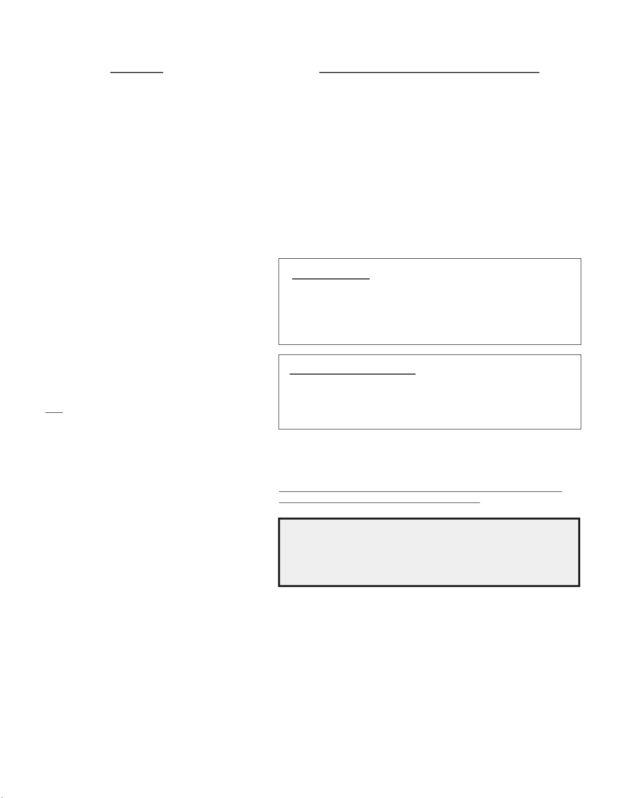
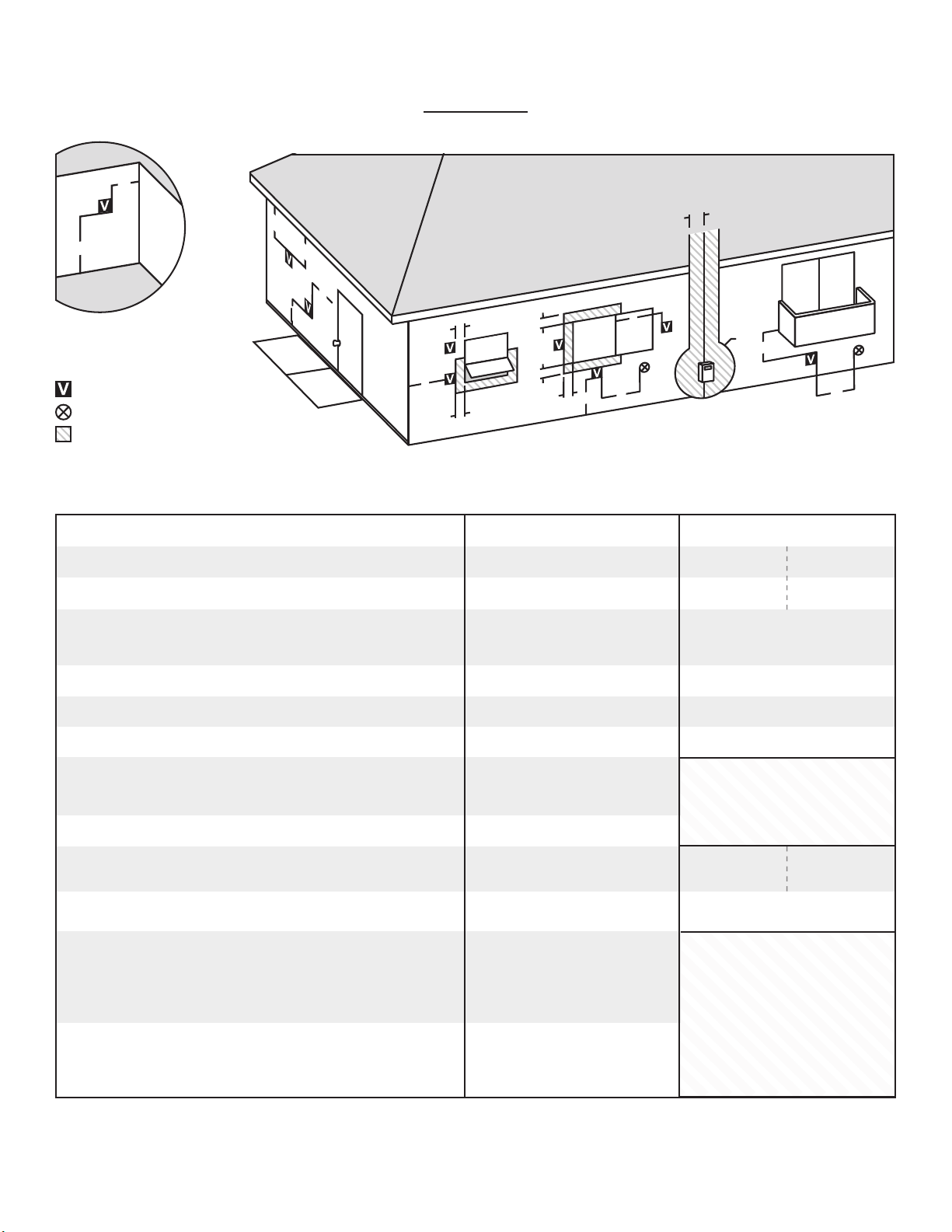
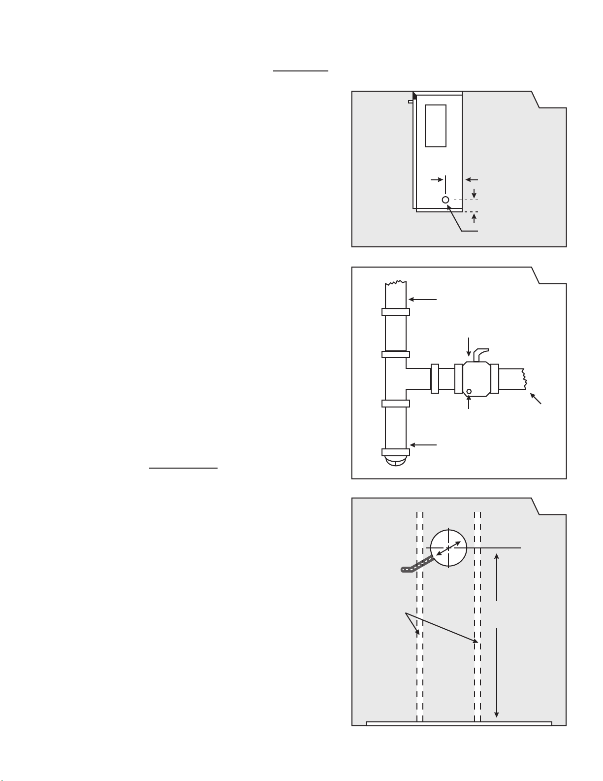
LOCATE VENT OPENING
After the location of the heater has been determined, the opening
for the vent pipe should be cut. If the heater is to be recessed, cut
for a 40,000 BTU model is 78-5/8”, for the 55,000 models the cut out
NOTE: This dimension may be increased to allow
more room for installation and making the wiring connection, then
renished.
pass through. The center of opening for the 40,000 BTU furnace is
See
Figure 5, on Page 6.
If the heater is to be surfaced mounted, cut out 9-1/4” opening
INSTALLING THE FURNACE
the exhaust or air intake tubes, this could cause an imbalance in the
heater resulting in poor performance and pilot outage (See Figure 6).
(see Figure 6).
GAS CONNECTION
must be run. Be sure to disconnect the gas supply line from the
appliance valve before pressure testing. The manifold pressure is
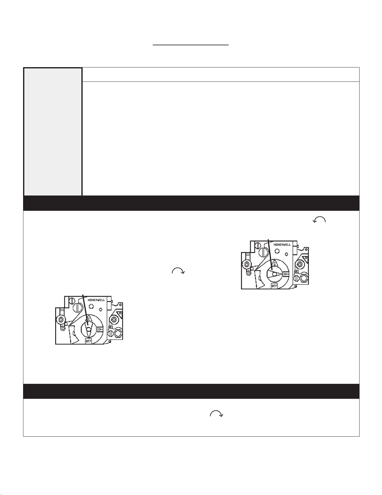
THERMOSTAT INSTALLATION
OPERATION
for heat the gas valve does not snap-open to full manifold pressure,
ignition.
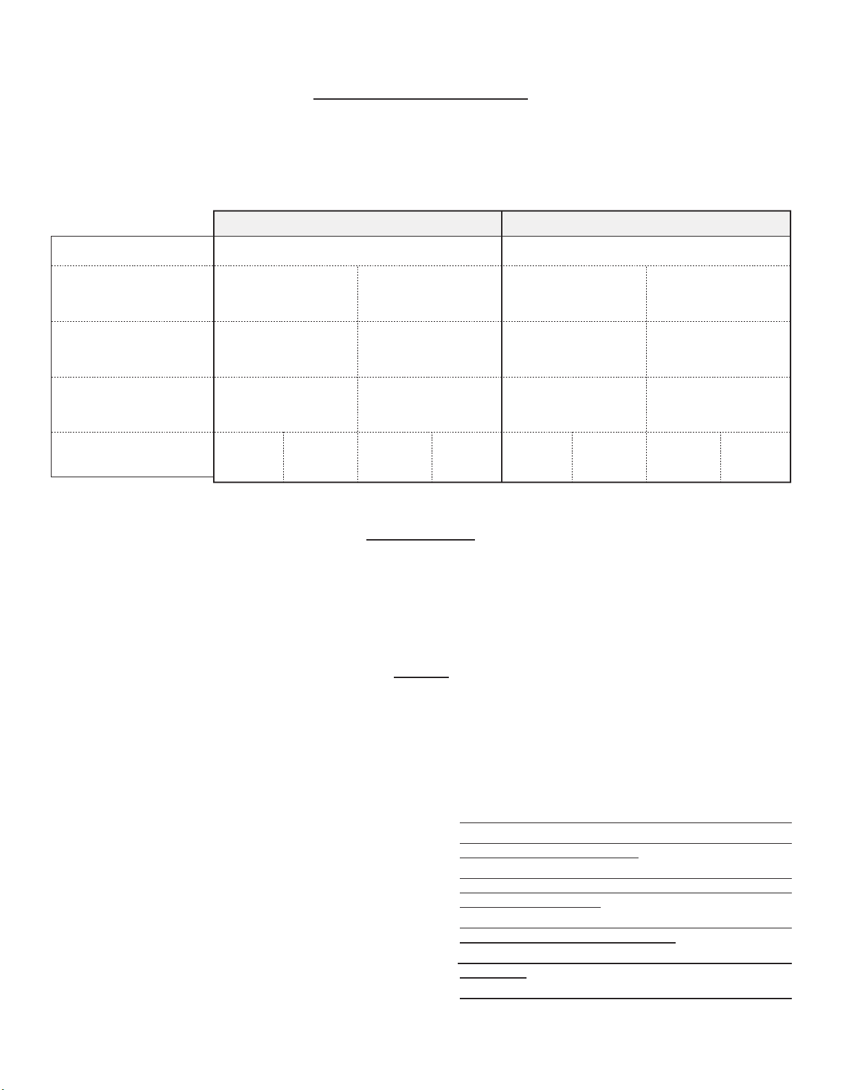
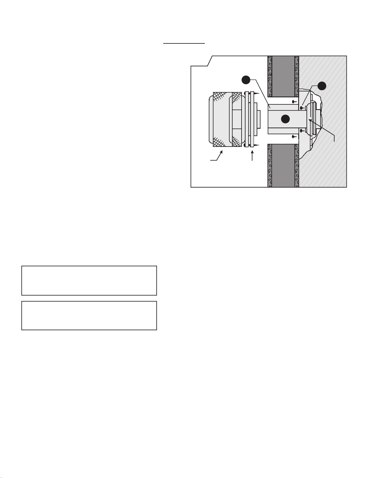
INLET AIR TUBE “A” – Measuring from gasketed
surface, mark and cut pipe same as dimension “X”.
VENT EXHAUST TUBE “B” – Measuring from
gasketed surface, mark and cut pipe 1-3/4” greater
Fasten vent exhaust tube “B” to heat exchanger collar and Inlet Air
provided. Be sure gaskets are in place and not damaged. Anytime
the vent pipes are removed check and replace gaskets (if necessary).
Failure to replace missing or damaged gaskets may expose
Secure furnace in place using 2 holes provided in bottom of casing.
NOTE: Make sure both tubes are centered in cut out. Slide the vent
cap onto the pipes extending from the back of the furnace. A rotating
or twisting motion will ease this installation. Secure vent cap and
caulking provided.
NOTE: Some framing may be necessary to provide a at surface
against the vent cap spacer plate and to prevent rain from entering
the wall opening.
Vent
Cap Vent Cap
Spacer Plate
WALL
“
X
”
OUTSIDE INSIDE
A
C
B
Heat
Exchange
Collar