2 of 3 LPN00305X0001A5_B
6
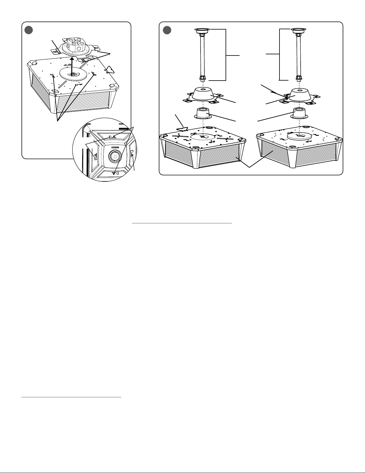
Pendant Mounting
Plate
Pendant Kit
(Supplied by
Customer)
Water Shield
Luminaire
5
(4) Luminaire Slots
(4) Clips
Mounting
Plate
View of Underneath
Luminaire
(4) Mounting
Plate Clips
Luminaire
Slots
(2) Screws
STEP 3:
Make wiring connections per “Electrical
Connections” section.
STEP 4:
After wiring connections have been made,
tuck all wires into junction box ensuring that
no wires are pinched. For luminaires with
wireform remove wireform on luminaire
from the clip on the mounting plate. Fold the
wireform back down onto the luminaire.
STEP 5:
Attach luminaire to the Mounting Plate by
pressing up on the luminaire until the slots
on the luminaire engage with the clips on
the Mounting Plate and rotate until clips lock
securely. To secure install a minimum of (2)
supplied screws across from each other into
the mounting plate clips on the underside of
the luminaire. See Figure 5.
NOTE: Installation may require extra pressure
on luminaire to engage clips into slots. Only
apply pressure on housing body NOT on the
luminaire lens.
NOTE: If the mounting plate clips become
deformed during installation, slightly reopen
the clips back up using a screwdriver to ensure
proper install of luminaire.
STEP 6:
Lightly pull on the luminaire to verify luminaire
is securely mounted.
FIXTURE SERVICING AND
MAINTENANCE
STEP 1:
If supply wiring splices need to be inspected
or if luminaire needs to be removed, fully
loosen the (2) screws and rotate luminaire to
disengage from Mounting Plate.
NOTE: For luminaires with wireform, locate
wireform on luminaire and attach it to
mounting plate to support luminaire during
splice inspection. See Figure 4.
STEP 2:
To re-install luminaire, when finished with
servicing or maintenance follow Step 2-6 in
“Junction Box Mounting” section above.
PENDANT MOUNTING (OPTIONAL)
NOTE: Customer supplied 3/4" IP Pendant
Kit and wire leads may be necessary for
pendant mounting. For existing rigid pendant
installations, perform Step 2 through 8
only. Not recommended for use with a hang
straight pendant. Cree does not provide a
counterbalance system.
NOTE: “J” Input Power Designator comes with
safety cable only. “A” Input Power Designator
comes with a safety cable or wireform.
STEP 1:
Feed wire leads through customer supplied
pendant kit. See Figure 6. Make sure leads are
at least 6 in longer than customer supplied
pendant stem.
STEP 2:
WITH SAFETY CABLE ( A or J Input Power
Designator)
Locate the safety cable on the luminaire and
attach the cable to the designated screw hole
on the Pendant Mounting Plate using the
provided screws. See Figure 1 and 3.
WITH WIREFORM ( A Input Power Designator)
Luminaries with wireform go to Step 3.
STEP 3:
WITH SAFETY CABLE ( A or J Input Power
Designator)
NOTE: Two people may be needed for installing
to customer supplied pendant kit, one to
hold the luminaire and another to install the
Pendant Mounting Plate to the customer
supplied pendant kit.
Attach Pendant Mounting Plate to customer
supplied pendant kit. See Figure 6.
WITH WIREFORM ( A Input Power Designator)
Attach Pendant Mounting Plate to customer
supplied pendant kit. See Figure 6.
STEP 4:
Feed wire leads through the Water Shield.
NOTE: Water Shield will be held in place by
the Pendant Mounting Plate. No fasteners are
necessary.
STEP 5:
For luminaires with Wireform, If wiring to a
previously installed pendant kit, locate the
wireform on luminaire and attach it to the clip
on the Pendant Mounting Plate for hands-free
wiring. See Figure 7.
STEP 6:
Make wiring connections to customer supplied
wire leads per “Electrical Connections”
section.
STEP 7:
After wiring connections have been made, tuck
all wires into the water shield ensuring that no
wires are pinched. If used, remove wireform
on the luminaire from the clip on the pendant
Mounting Plate. Fold wireform back down onto
luminaire.
NOTE: Ensure that splices are contained within
Water Shield for future splice inspections.
STEP 8:
Attach luminaire to the Pendant Mounting
Plate by engaging the clips on the Pendant
Mounting Plate with the slots on the luminaire.
Rotate until clips lock securely. See Figure 7.
NOTE: May require extra pressure on Pendant
Mounting Plate to engage luminaire clips into
slots.
STEP 9:
Install a minimum of (2) supplied screws
into the pendant mounting plate clips on the
underside of the luminaire. See Figure 7.
Safety Cable
Wireform


