manuals.online logo
Brands
  1. Home
  2. •
  3. Brands
  4. •
  5. CREE LIGHTING
  6. •
  7. Outdoor Light
  8. •
  9. CREE LIGHTING SYRIUS User manual

CREE LIGHTING SYRIUS User manual

SYRIUS™
Street Lights Luminaires
Includes: Syrius™
INSTALLATION INSTRUCTIONS
IEC 60598
Instrucon Code: CI122RLER1
Latest Release Date: 06/03/2020
EN: TECHNICAL DATA
• Voltage & Frequency:
220–240 V ~ 50/60 Hz
150-240V~ 50/60 Hz (option RF#)
• Input Current
min 0.03A @230V
max 0.20A @230V
max 0.28A @150V
• Power Factor: ≥ 0.98 (full load)
• IP rating: IP 66
• Insulation class: Class I or II
• Installation method: Fixed, outdoor
use.
• TA min/max (°C): –40°C / +50°C
• Max. weight: 6.5 kg (with fitter)
5.2 kg (without fitter)
• Max. wind area: 0.058 m2
• Range of mounting heights: < 12 m
• Risk group EXEMPT according to
IEC 62471:2008
IT: INFORMAZIONI TECNICHE
• Tensione di Alimentazione:
220-240V ~ 50/60 Hz
150-240V ~ 50/60 Hz (opzione RF#)
• Corrente di Alimentazione:
max 0.03A @ 230V
min 0.20A @ 230V
max 0.28A @150V
• Power Factor: ≥ 0.98 (pieno carico)
• Grado di protezione IP: IP66
• Classe Isolamento: Classe I o II
• Cond. Installazione: Fissa, uso
esterno. Utilizzabile anche per in-
stallazioni interne.
• Ta min/ max (°C): -40°C / +50°C
• Peso Max: 6.5 kg (con testapalo)
5,2 kg (senza tastapalo)
• Max Superficie Esposta al vento:
0,058 m2
• Altezza di Installazione: < 12 m
• Gruppo di Rischio ESENTE in accordo
alla IEC 62471:2008
EN: WARNINGS IT: ATTENZIONE
• Keep a copy of this instruction sheet.
• Electrical connection may be done only by competent users; Com-
pany denies any responsibilities for any problem occurring from
improper installation.
• For Class I versions, make sure to connect ground lead.
• For Class II versions, DO NOT connect ground lead.
• Before opening fixture switch off the line.
• Maintenance cleaning must be restricted to external surfaces.
• Take care to keep the glass clean during installation.
• Ensure the mounting surface is capable of supporting the weight of
the luminaire after the installation.
• Make sure fixture is properly aimed: use as reference photometric
curve.
• If the external flexible cable or cord of this luminaire is damaged, it
shall be exclusively replaced by the manufacturer or his service
agent or a similar qualified person in order to avoid a hazard.
• The light source contained in this luminaire shall only be replaced
by the manufacturer or his service agent or a similar qualified per-
son.
• Conservare una copia del presente foglio istruzioni.
• Il collegamento elettrico ed eventuali interventi in caso di malfunzionamento devono
essere eseguiti solo da personale tecnico competente; l’azienda declina ogni re-
sponsabilità qualora l’installazione non avvenga secondo le norme vigenti.
• Negli apparecchi in Classe I effettuare il collegamento di terra.
• Negli apparecchi in Classe II non connettere il cavo di terra.
• Prima di aprire l’apparecchio togliere tensione dalla linea di rete.
• La pulizia va limitata alle superfici esterne.
• Fare attenzione a mantenere le lenti dei LED pulite durante l’installazione.
• Assicurarsi che il palo di fissaggio sia dimensionato per supportare il peso dell’ap-
parecchio.
• Porre attenzione al puntamento del proiettore: riferirsi alla curva fotometrica.
• Se il cavo flessibile esterno di questo apparecchio viene danneggiato deve essere
sostituito esclusivamente dal costruttore, dalla sua rete assistenza o da personale
qualificato equivalente, al fine di evitare pericoli.
• La sorgente luminosa contenuta in questo apparecchio deve essere sostituita esclu-
sivamente dal costruttore, dalla sua rete assistenza o da personale qualificator
equivalente.
FRA: Pour les instructions en franςais, voir: http://www.creelighting-europe.com/en/product/cree-syrius-ip66-series
ESP: Para instrucciones en español ver: http://www.creelighting-europe.com/en/product/cree-syrius-ip66-series
DEU: Anleitung in Deutsch siehe: http://www.creelighting-europe.com/en/product/cree-syrius-ip66-series
Instrucon Code: CI122RLER1
Pg.2/4
EN: LUMINAIRES WITH NEMA RECEPTACLE / IT: APPARECCHI PROVVISTI DI PRESA NEMA
EN: Technical information NEMA receptacle
Available Voltage: 220-240 Vac
Max available current: 4 A
Frequency: 50/60 Hz
The fixture equipped with NEMA receptacle was designed for working connected to a NEMA device that must be compliance with the ANSI C136.41-2013
standard.
Regulatory tests were done by connecting a NEMA Shorting Cap (Lucy Zodion Dummy Cap) that meets the ANSI C136.41-2003.
• Without a NEMA equipment connected the fixture doesn’t work.
• The IP rating of the fixture without NEMA device connected is the same IP rating of the NEMA receptacle without Shorting Cap, thus IP20.
• The IP66 degree and sealing the entrance of dust and water are not guaranteed once replaced the shorting cap
IT: Informazioni Tecniche Presa Nema
Tensione nominale: 220-240 Vac
Corrente Nominale: Max 4 A
Frequenza: 50 / 60 Hz
Gli apparecchi provvisti di presa Nema sono stati ideati per funzionare con un dispositivo Nema conforme alla ANSI C136.41-2013.
Tutti i relativi test di conformità e di durata sono stati effettuati utilizzando uno Shorting Cap (Lucy Zodion Dummy Cap) conforme a tale normativa.
• Senza dispositivo Nema connesso all’apparecchio quest’ultimo non si accende.
• Il grado di protezione IP dell’apparecchio senza dispositivo Nema connesso è pari al grado di protezione IP della presa NEMA privo di Shorting Cap, di
conseguenza è pari a IP20.
• Una volta sostituito lo Shorting Cap in dotazione il grado di protezione IP66 all’ingresso di acqua e polvere non è più garantito.
EN: LUMINAIRES WITH ZHAGA BOOK 18 RECEPTACLE / IT: APPARECCHI PROVVISTI DI PRESA ZHAGA
EN: Technical data on ZHAGA sockets
Nominal voltage: 30 Vdc
Nominal current: max 1.5 Adc
The fittings equipped with ZHAGA sockets are designed for operating with a plug-in device conforming to the Zhaga Book 18. All compliance and reliability
tests, including the IP66 and IK tests, were carried out using a Zhaga Book 18 sealing cap (TE Lumawise Endurance S - 2213795).
• The IP rating of the fitting without a Zhaga Book 18 device or a Zhaga Book 18 Sealing Cap connected is the same as the IP rating of the Zhaga Book 18
Receptacle, namely IP20.
• The IP66 rating and sealing preventing the entry of dust and water are not guaranteed once the sealing cap is removed.
IT: Informazioni tecniche presa ZHAGA
Tensione nominale: 30 Vdc
Corrente nominale: max 1,5 Adc
Gli apparecchi provvisti di presa ZHAGA sono stati ideati per funzionare con un dispositivo plug-in conforme allo Zhaga Book 18. Tutti i relativi test di con-
formità e affidabilità, inclusi i test IP66 e IK, sono stati effettuati utilizzando uno Sealing Cap (TE Lumawise Endurance S - 2213795).
• Il grado di protezione IP dell’apparecchio senza dispositivo Zhaga Book 18 o Zhaga Book 18 Sealing Cap connesso è pari al grado di protezione IP della
presa Zhaga Book 18 Receptacle, ovvero IP20.
• Il grado IP66 e la tenuta all’ingresso di polvere e acqua non sono garantiti una volta sostituito la sealing cap.
LV SUPPLY vs CONTROL CONDUCTORS: CLASSIFICATION OF INSULATION
Option Insulation
DIM—DL BASIC
SR REINFORCED
EN: INSTALLATION INSTRUCTION / IT: ISTRUZIONI INSTALLAZIONE
EN: INSTALLATION
STEP 1: Pass the cable coming out of the appliance
through the pole-top.
STEP 2: Open the appliance by unscrewing the two tool
free screws and orient the pole-top in a vertical or hori-
zontal position, aligning the pole-locking clamp teeth with
those on the appliance; look in the adjustment window to
check and / or correct the selected angle.
STEP 3: Connect the pole-top unit to the appliance using
the two M10 hexagonal-head screws with a 13 mm soc-
ket wrench using the relative supports (backing) tighte-
ning to 12 Nm (106 lbs-in). For class II appliances insert
the eyelet in the underhead of one of the two M10 screws
before tightening. Close the appliance and tighten the
two tool free screws to 2 Nm, then secure the eyelet, if
any, in one of the 6 special safety locks.
STEP 4: Slide the pole-top on the shank, reaching the
internal ledge and lightly tighten the two M10 screws
with a hexagon socket using a 5mm Allen key.
STEP 5: Rotate the unit on the shank to properly level
the position of the appliance.
STEP 6: Firmly tighten the two M10 dowels with hexagon
socket several times with a tightening torque of 16 Nm to
18 Nm (141.5 lbs-in and 160.0 lbs-in).
STEP 7: Tighten the nut and locknut securely for each
grain with a tightening torque of 16 Nm to 18 Nm (141.5
lbs-in and 160.0 lbs-in).
M10 Screws and backings for head-
pole xing on housing
Nuts, grains and
plate for head-
pole xing on pole
Cable holes
Adjustment notches
IT: INSTALLAZIONE
FASE 1: Passare il cavo uscente dall’apparecchio attraverso il testapalo.
FASE 2: Aprire l’apparecchio svitando le due viti tool free ed orientare il testapalo in posizione verticale od orizzontale, allineando i denti di bloccaggio del
testapalo con quelli sull’apparecchio; traguardare nella finestra di regolazione per verificare e/o correggere l’angolo scelto.
FASE 3: Collegare il testapalo all’apparecchio usando le due viti M10 a testa esagonale con chiave a tubo da 13 mm mediante i relativi appoggi (backing)
serrando a 12 Nm (106 lbs-in). Per apparecchi in classe II inserire l’occhiello nel sottotesta di una delle due viti M10 prima di serrare. Chiudere l’apparec-
chio e serrare le due viti tool free a 2 Nm, assicurare poi l’occhiello, se presente, in uno dei 6 appositi blocchi di sicurezza.
FASE 4: Far scorrere il testapalo sul codolo, raggiungendo la battuta interna e stringere leggermente i due grani da M10 con cava esagonale mediante
chiave a brugola da 5mm.
FASE 5: Ruotare il gruppo sul codolo per pareggiare adeguatamente la posizione dell’apparecchio.
FASE 6: Serrare saldamente a più riprese i due grani M10 con cava esagonale mediante una coppia di serraggio compresa tra 16 Nm and 18 Nm (141,5 lbs
-in and 160,0 lbs-in).
FASE 7: Serrare saldamente dado e controdado per ogni grano con una coppia di serraggio compresa tra 16 Nm e 18 Nm (141,5 lbs-in and 160,0 lbs-in).
Tool-free screws
M10 Screws and
backings for
head-pole xing
on housing. For
Class II luminai-
res, x the pink
cable with M10
eyelet with the
right screw on
the head-pole
Nuts and grains
xed on the pole
WARNING: To avoid the possibility of electrical shock, turn off power supply before making any electrical connections.
ATTENZIONE: Per evitare il pericolo di scossa elettrica, togliere l’alimentazione prima di effettuare i collegamenti elettrici.
EN: For the luminaires without internal fuse, it is recommended to use an external 8 A delayed fuse.
IT: Per gli apparecchi senza fusibile interno, si raccomanda l’utilizzo di un fusibile esterno da 8 A ritardato.
EN: For luminaires without cable (with and without NEMA or Zhaga connector):
- Remove cable outside insulation for 4 mm, remove 2nd insulation of cable leads for max. 8 mm
- See Table 1 for cable tightening, Table 2-A for conventional symbols used on the connectors and Table 2-B Columns “Color - Internal wire”, “Color -
Outgoing cable” and “Function” for conventional colours used on internal wires and outgoing cable related to the wire’s function.
IT: Per apparecchi senza cavo uscente (con e senza connettore Nema o Zhaga):
- Rimuovere l’isolamento esterno del cavo per 4 mm, rimuovere l’isolamento dei singoli cavi per un max di 8 mm
- Vedere Tabella 1 per il serraggio del cavo, Tabella 2-A per la convenzione dei simboli usata sui connettori e Tabella 2-B Colonne “Color - Internal wire”,
“Color - Outgoing cable” e “Function” per la convenzione dei colori usata sui cavi interni e sul cavo uscente in relazione alla funzione dei cavi.
EN: For the luminaires with cable, please see the connector’s instruction, if present, and Table 2-B Column “Color - Outgoing cable” and “Function” for
the conventional colours used on the outgoing cable.
- The fixture comes with a H07RN-F 3x1.5, H07RN-F 4x1,5 or H07RN-F 5x1,5 cable certified for outdoor and indoor use.
- Make the electrical connection using a terminal block conforming to the standard EN 60998-2-1 or EN 60998-2-2.
IT: Per gli apparecchi provvisti di cavo, vedere le istruzioni del connettore esterno, se presente, e la Tabella 2-B Colonna “Color - Outgoing cable” e
“Function” per la convenzione dei colori usata sul cavo uscente.
- L’apparecchio include cavo del tipo H07RN-F 3x1.5, H07RN-F 4x1,5 or H07RN-F 5x1,5 certificato per uso interno ed esterno.
- Per la connessione elettrica utilizzare una morsettiera conforme alla EN60998-2-1 o EN 60998-2-2.
EN: WIRING INSTRUCTIONS / IT: ISTRUZIONI DI CABLAGGIO
Instrucon Code: CI122RLER1
Pg.3/4
TABLE 1 - CABLE TIGHTENING
EN: Open the
flap and loosen
the cable gland.
Feed the power
cable through the
cable gland.
IT: Aprire lo
sportello e allen-
tare il pressa
cavo. Passare il
cavo di alimenta-
zione attraverso il
pressa cavo.
EN: Strip each wire of the cable
as shown in Figure 1.
IT: Spelare i singoli cavi secondo
lo schema illustrato in figura 1.
EN: Make the connection as shown in the
figure and in table 2.
IT: Effettuare la connessione come mostra-
to in figura e nella tabella 2.
EN: Tighten the cable clamp and the cable gland
by applying a 3 Nm torque.
IT: Serrare il serracavo ed il pressacavo in ingres-
so applicando una coppia di 3Nm.
TABLE 2-A - COMPONENTS FOR CLASS I AND CLASS II APPLIANCES WITH OR WOTHOUT REMOVABLE PLATE
2 POLES 2 POLES + EARTH 3 AND 4 POLES 3 AND 4 POLES + EARTH
APPLIANCES WITHOUT
REMOVABLE PLATE
APPLIANCES WITH RE-
MOVABLE PLATE
L
N
Switch
L2
L3
N
L1
Switch
L
N
Terminal
L
N
Terminal
L2
L3
L1
N
Terminal
L3
L2
N
L1
Terminal
TABLE 2-B - DIAGRAM FOR CABLE WIRING
OPTION INSULATION
CLASS
Color -
Internal
wire
FUNCTION STANDARD option NEMA option
Color -
Outgoing
cable
For both remova-
ble plate or no
removable plate
version:
Adjustable Output
Current (AOC)
Virtual Midnight +
Constant Lumen
Output Lite (VML)
Only for removable
plate version:
Virtual Midnight +
Constant Lumen
Output Full (VMF)
Flux Regulator
(RF)
Sensor Ready (SR)
Virtual Midnight +
Constant Lumen
Output Full on
Sensor ready
(VMS)
II
Brown Line (L)
Brown
Blue Neutral (N)Blue
I
Brown Line (L)
Brown
Green&
Yellow Earth ( )
Green&
Yellow
Blue Neutral (N)Blue
Only for removable
plate version:
Lineswitch (G)
II
Brown Line (L1)
Brown
Black Line 2 (Pilot)
(L2)
Black
Blue Neutral (N)Grey
I
Brown Line (L1)
Brown
Blue Neutral (N)Grey
Green&
Yellow Earth ( )
Green&
Yellow
Black Line 2 (Pilot)
(L2)
Black
For both remova-
ble plate or no
removable plate
version:
1-10 V Dimmable
(DIM)
Only for removable
plate version:
Dali (DL)
II
Brown Line (L1)
Brown
Blue Neutral (N)Blue
Grey 1-10V- /Dali
(L2)
Grey
Purple/Red 1-10V+ /Dali
(L3)
Black
I
Brown Line (L1)
Brown
Blue Neutral (N)Blue
Green& Yellow Earth ( )Green& Yellow
Grey/Black 1-10V- /Dali
(L2)
Grey
Purple/Red 1-10V+ /Dali
(L3)
Black
N
L1
L2
N
L1
L2
L3
L2
N
L1
L1
L2
L3
N
L
N
L
N
L
N
L
N
Cable lock
Cable lock
Switch or
Terminal
Cable lock
Switch
Cable lock
Switch
Cable lock
Cable lock
Switch or
Terminal
Switch or
Terminal
Switch or
Terminal
L1
L3
N
N
L1
L2
L3
Cable lock
Switch or
Terminal
Cable lock
Switch or
Terminal
L1
L3
N
Cable lock
Switch or
Terminal
N
L1
L2
L3 Cable lock
Switch or
Terminal
DIRECTIVE 2012/19/EU (WASTE ELECTRICAL AND ELECTRONIC EQUIPMENT –WEEE): Information for users.
This product complies with EU Directive 2012/19/EU. The crossed-out wastebasket symbol on the appliance means that at the end of its useful lifespan, the product must be disposed of separately from
ordinary household wastes. The user is responsible for delivering the appliance to an appropriate collection facility at the end of its useful lifespan. Appropriate separate collection to permit recycling, treatment
and environmentally compatible disposal helps prevent negative impact on the environment and human health and promotes recycling of the materials making up the product. For more information on available
collection facilities, contact your local waste collection service or the shop where you bought this appliance.
DIRETTIVA 2012/19/UE (RIFIUTI DI APPARECCHIATURE ELETTRICHE ED ELETTRONICHE - RAEE): Informazioni agli utenti.
Ai sensi dell’art. 26 del Decreto Legislativo 14 Marzo 2014, n. 49 "Attuazione delle Direttive 2012/19/UE, relative alla riduzione dell'uso di sostanze pericolose nelle apparecchiature elettri-
che ed elettroniche, nonché allo smaltimento dei rifiuti" questo prodotto è conforme. Il simbolo del cassonetto barrato riportato sull’apparecchiatura o sulla sua confezione indica che il prodotto alla
fine della propria vita utile deve essere raccolto separatamente dagli altri rifiuti. L’utente dovrà, pertanto, conferire l’Apparecchiatura giunta a fine vita agli idonei centri di raccolta differenziata dei Rifiuti Elettro-
nici ed Elettrotecnici, oppure riconsegnarla al rivenditore al momento dell’acquisto di una nuova apparecchiatura di tipo equivalente, in ragione di uno a uno. L’adeguata raccolta differenziata per l’avvio succes-
sivo dell’apparecchiatura dismessa al riciclaggio, al trattamento ed allo smaltimento ambientalmente compatibile contribuisce ad evitare possibili effetti negativi sull’ambiente e sulla salute e favorisce il reimpie-
go e/o riciclo dei materiali di cui è composta l’apparecchiatura. Lo smaltimento abusivo del prodotto da parte dell’utente comporta l’applicazione delle sanzioni amministrative previste dalla normativa vigente.
© 2020 Cree Lighng, A company of IDEAL INDUSTRIES. All rights reserved. For
informaonal purposes only. Content is subject to change. Patent
www.creelighng.com/patents. Cree® and the Cree logo are registered trademarks and
the Cree SmartCast Technology logo is a trademark of Cree, Inc. SmartCast® is a regis-
tered trademark and OneBuon™ is a trademark of Cree Lighng, A company of IDEAL
INDUSTRIES. The UL Logo is a registered trademark of UL LLC.

Other CREE LIGHTING Outdoor Light manuals

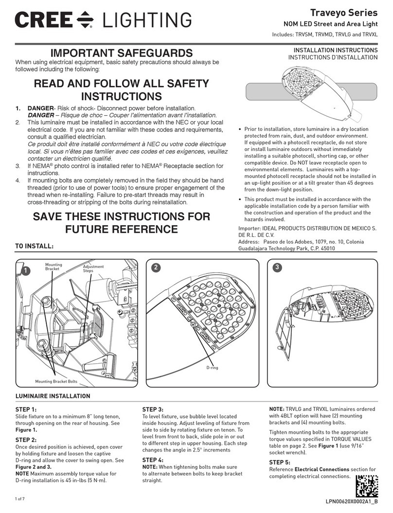
CREE LIGHTING Traveyo Series User manual

CREE LIGHTING

CREE LIGHTING Traveyo Series User manual

CREE LIGHTING Traveyo Series User manual

CREE LIGHTING

CREE LIGHTING Traveyo Series User manual

CREE LIGHTING THE EDGE XPS Transportation Series User manual

CREE LIGHTING

CREE LIGHTING THE EDGE XPS Transportation Series User manual

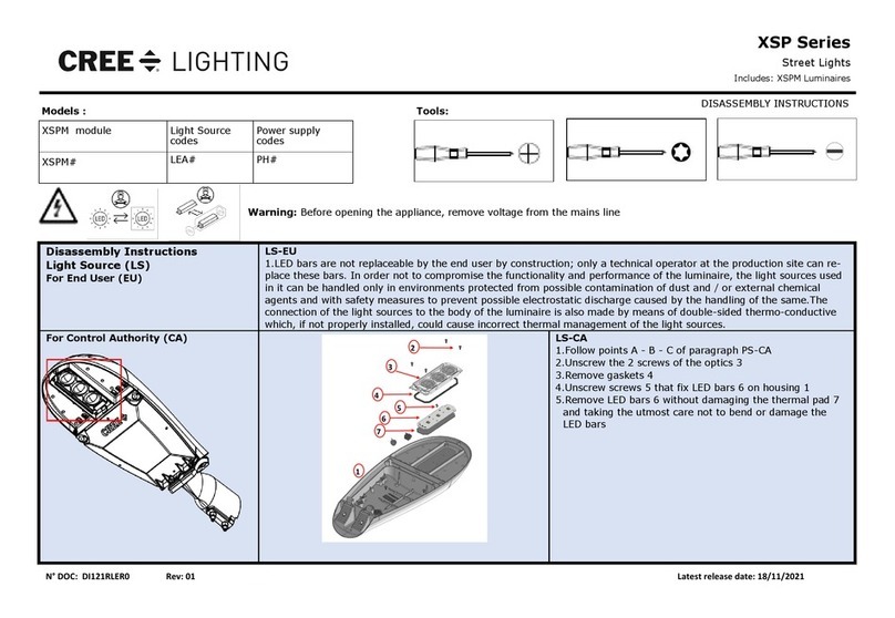
CREE LIGHTING XSP Series Installation instructions

CREE LIGHTING

CREE LIGHTING XSP Series Installation instructions

CREE LIGHTING VSL Series User manual

CREE LIGHTING

CREE LIGHTING VSL Series User manual

CREE LIGHTING XSP Series User manual

CREE LIGHTING

CREE LIGHTING XSP Series User manual

CREE LIGHTING SYRIUS SYS-A Series User manual

CREE LIGHTING

CREE LIGHTING SYRIUS SYS-A Series User manual

CREE LIGHTING OSQ Series User manual

CREE LIGHTING

CREE LIGHTING OSQ Series User manual

CREE LIGHTING IG Series User manual

CREE LIGHTING

CREE LIGHTING IG Series User manual

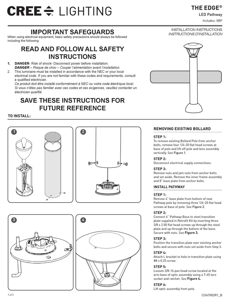
CREE LIGHTING EDGE Series User manual

CREE LIGHTING

CREE LIGHTING EDGE Series User manual

CREE LIGHTING IG Series User manual

CREE LIGHTING

CREE LIGHTING IG Series User manual

CREE LIGHTING 304 Series Installation instructions

CREE LIGHTING

CREE LIGHTING 304 Series Installation instructions

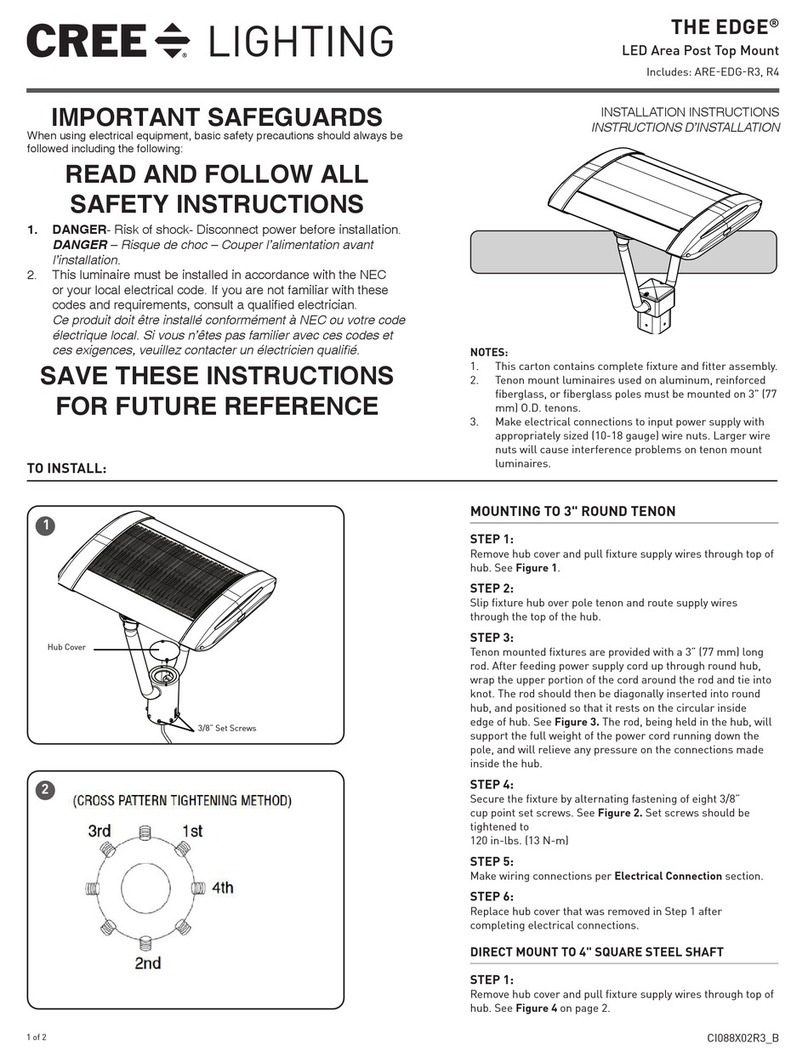
CREE LIGHTING EDGE ARE-EDG-R3 User manual

CREE LIGHTING

CREE LIGHTING EDGE ARE-EDG-R3 User manual

CREE LIGHTING LEDway Series Installation instructions

CREE LIGHTING

CREE LIGHTING LEDway Series Installation instructions

Popular Outdoor Light manuals by other brands

LIGMAN AUGUSTA 5 installation manual

LIGMAN

LIGMAN AUGUSTA 5 installation manual

HEPER DOMINI 12 LED Installation & maintenance instructions

HEPER

HEPER DOMINI 12 LED Installation & maintenance instructions

Westinghouse 6122600 owner's manual

Westinghouse

Westinghouse 6122600 owner's manual

BEGA 204 Instructions for use

BEGA

BEGA 204 Instructions for use

HEPER TURA 2x16 LED Installation & maintenance instructions

HEPER

HEPER TURA 2x16 LED Installation & maintenance instructions

Vaxcel T0321 Assembly and installation instructions

Vaxcel

Vaxcel T0321 Assembly and installation instructions

Trilux CUVIA LED Mounting instructions

Trilux

Trilux CUVIA LED Mounting instructions

Clas Ohlson LS7H01-UK instruction manual

Clas Ohlson

Clas Ohlson LS7H01-UK instruction manual

LIGMAN VANCOUVER 61 installation manual

LIGMAN

LIGMAN VANCOUVER 61 installation manual

Nemo Studio LUX WALKWAY Mounting instructions

Nemo Studio

Nemo Studio LUX WALKWAY Mounting instructions

Sulion 200775 instruction manual

Sulion

Sulion 200775 instruction manual

PROLUMIA Pro-Fit + Photocell operating instructions

PROLUMIA

PROLUMIA Pro-Fit + Photocell operating instructions

Totec AMA-SW01 quick guide

Totec

Totec AMA-SW01 quick guide

TVILIGHT CitySense Plus installation manual

TVILIGHT

TVILIGHT CitySense Plus installation manual

Lumie Zip operating instructions

Lumie

Lumie Zip operating instructions

Lasvit Tac Tile CL028FA-2CE manual

Lasvit

Lasvit Tac Tile CL028FA-2CE manual

Maxim Artisan 3174CLBK quick start guide

Maxim

Maxim Artisan 3174CLBK quick start guide

Trilux 9311 LED Mounting instructions

Trilux

Trilux 9311 LED Mounting instructions

manuals.online logo
manuals.online logoBrands
  • About & Mission
  • Contact us
  • Privacy Policy
  • Terms and Conditions

Copyright 2025 Manuals.Online. All Rights Reserved.