manuals.online logo
Brands
  1. Home
  2. •
  3. Brands
  4. •
  5. CREE LIGHTING
  6. •
  7. Outdoor Light
  8. •
  9. CREE LIGHTING THE EDGE XPS Transportation Series User manual

CREE LIGHTING THE EDGE XPS Transportation Series User manual

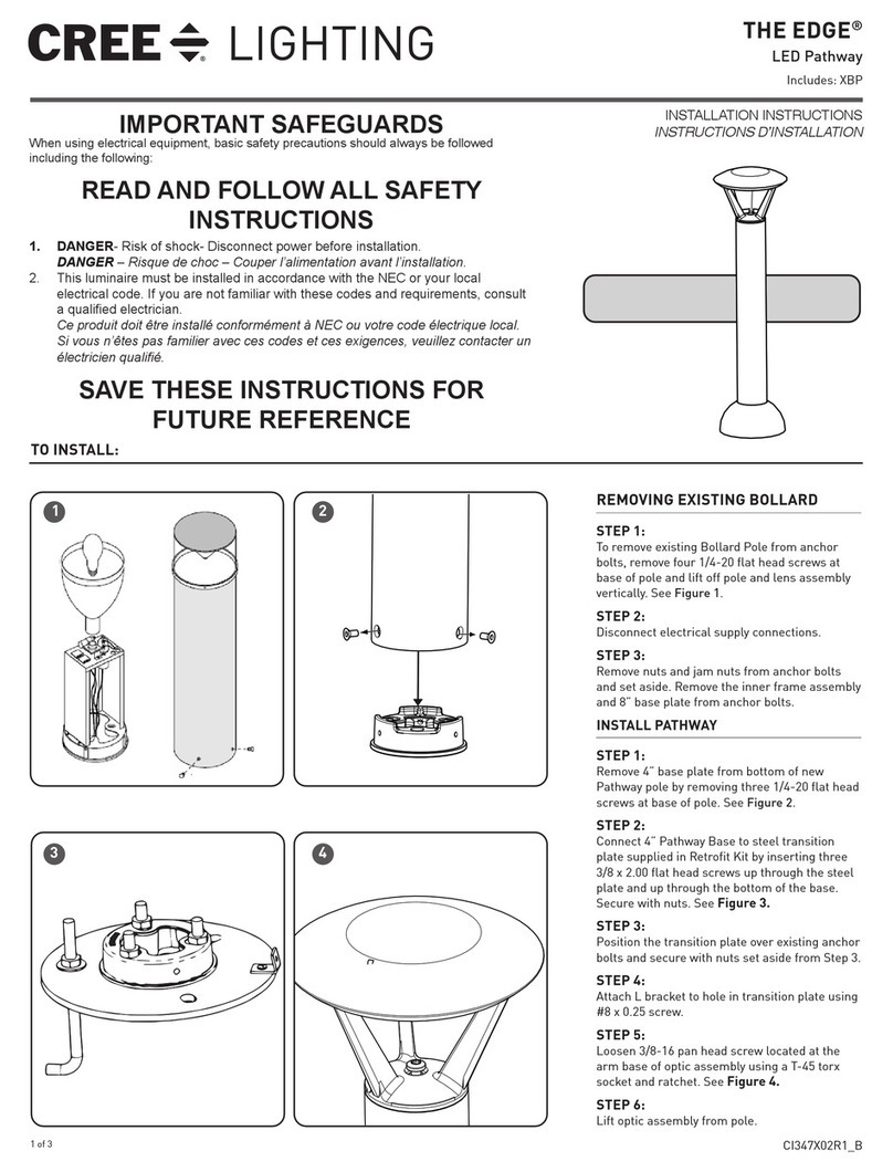
THE EDGE®
XPS Transportation Series
Catenary Mount
1 of 2 CI367X02R1_B
INSTALLATION INSTRUCTIONS
INSTRUCTIONS D’INSTALLATION
TO INSTALL:
CABLE MOUNTING
STEP 1:
Luminaire is supplied with adjustable brackets to
accommodate cables of various diameters. For cables 8
mm – 12.7 mm, keep the Reduction Brackets in place. For
cables 12.7 mm – 25.4 mm remove the reduction brackets.
See Figure 1.
STEP 2:
After the bracket is adjusted accordingly, hang the
luminaire on the cable and tighten the (2) retained cable
bracket bolts. See Figure 2.
STEP 3:
Tighten the bolts on outer perimeter shown in figure 3 to
180 in/lbs.
ADJUSTING LUMINAIRE POSITION
NOTE: The luminaire leaves the factory in a position based
on a rigid cable in perfect horizontal position running on
transversal plane to the lamp axis.
STEP 1:
Based on the vertical tilt and the horizontal orientation
of cable, the luminaire can be adjusted to ensure proper
illumination. This can be done by loosening the adjustment
bolts and moving the luminaire into the desired position.
See Figure 3.
STEP 2:
Re-tighten the loosened bolts.
STEP 3:
Tighten the bolts on outer perimeter shown in figure 3 to
180 in/lbs.
STEP 4:
After the luminaire is installed and positioned correctly,
make wiring connections per the Electrical Connections
section.
Reduction Bracket for
Cable Diameters from
5/16” to 1/2”
Remove Reduction Bracket
for Cable Diameters from
1/2” to 1”
1
Tighten Bolts
to Secure Cable
Brackets
Cable
Adjustment Bolts
2
3
IMPORTANT SAFEGUARDS
When using electrical equipment, basic safety precautions should always be
followed including the following:
READ AND FOLLOW ALL SAFETY
INSTRUCTIONS
1. DANGER- Risk of shock- Disconnect power before installation.
DANGER – Risque de choc – Couper l’alimentation avant l’installation.
2. This luminaire must be installed in accordance with the NEC or your local
electrical code. If you are not familiar with these codes and requirements,
consult a qualied electrician.
Ce produit doit être installé conformément à NEC ou votre code électrique
local. Si vous n’êtes pas familier avec ces codes et ces exigences, veuillez
contacter un électricien qualié.
3. Damage to luminaire will result when improper voltage is applied. Verify
luminaire is suitable for supply voltage by checking electrical label on luminaire.
SAVE THESE INSTRUCTIONS FOR FUTURE
REFERENCE
NOTE: Before installing, ensure the mounting surface,
cable and the cable securement points are structurally
sound and capable of supporting the weight of the
luminaire
Bolts on Outer
Perimeter
2 of 2 CI367X02R1_B
www.creelighting.com
© 2019 Cree Lighting, A company of IDEAL INDUSTRIES. All rights reserved. For informational purposes only. Content is
subject to change. See www.creelighting.com/warranty for warranty and specifications. Cree®and the Cree logo are registered
trademarks of Cree, Inc. THE EDGE®is a registered trademark of Cree Lighting, A company of IDEAL INDUSTRIES.
ELECTRICAL CONNECTIONS
STEP 1:
After the luminaire is installed and positioned correctly, open the
Junction Box Cover on the luminaire by removing the two (2) screws
and set aside.
STEP 2:
Using Listed 90°C minimum rated wire connectors make the following
electrical connections within the junction box:
a. Connect the black luminaire lead to the voltage supply position of
the terminal block.
b. Connect the white luminaire lead to the neutral supply position of
the terminal block.
c. Connect the green ground lead to the green wire position of the
terminal block.
d. If Dimming is an option; connect the violet dimming positive lead
to the supply dimming positive lead.
e. If Dimming is an option; connect the grey dimming negative lead
to the supply dimming negative lead.
BLACK
GREEN
LINE-BLACK
GROUND-GREEN
NEUTRAL-WHITE
DIM (-) GREY
DIM (+) VIOLET
WHITE
VIOLET
GREY
SUPPLY WIRING
(DIMMING OPTIONAL)
LUMINAIRE
TERMINAL
BLOCK
HLOPTION ELECTRICAL CONNECTIONS
LOW MODE (175 mA): 40-160 LEDS
Low Mode is enabled when voltage is applied to Line 1 and Line 2 is de-
energized (0 volts applied).
STANDARD MODE (350 mA): 40-160 LEDS
Standard Mode is enabled when voltage is applied to Line 2 and Line 1 is
de-energized (0 volts applied).
STANDARD MODE (350 mA): 40-120 LEDS
Standard Mode is enabled when voltage is applied to both Line 1 and
Line 2.
HIGH MODE (525 mA): 40-120 LEDS
High Mode is enabled when voltage is applied to both Line 1 and Line 2.
Line 1 - 175 mA Line 2 - 175mA (140-160 Leds)
Line 2 - 350 mA (20-60 Leds)
Drive Current Output
(mA)
ON OFF 175
OFF ON 350
ON ON (20-60 LEDS) 525
ON ON (140-160 LEDS) 350
LUMINAIRE WIRING: HL-Option luminaire wiring is Phase to
Neutral only. Refer to wiring diagram on the right for the appropriate
connections.
BLACK
GREEN
L1-BLACK
GROUND-GREEN
NEUTRAL-WHITE WHITE
SUPPLY WIRING
LUMINAIRE
LUMINAIRE
J-BOX
CORD
RED
L2-RED
SWITCH OR
SENSOR
SUPPLIED BY
CUSTOMER

Other CREE LIGHTING Outdoor Light manuals
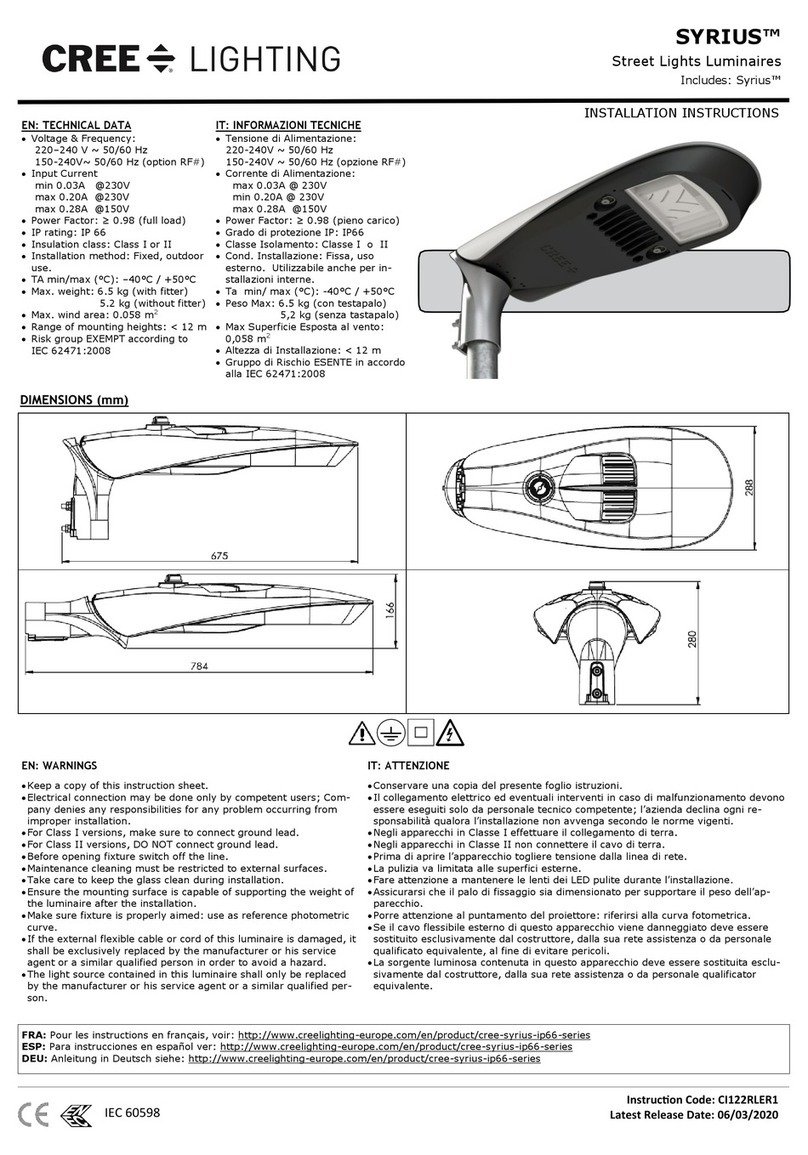
CREE LIGHTING Traveyo Series User manual

CREE LIGHTING

CREE LIGHTING Traveyo Series User manual

CREE LIGHTING Traveyo Series User manual

CREE LIGHTING

CREE LIGHTING Traveyo Series User manual

CREE LIGHTING 304 Series Installation instructions

CREE LIGHTING

CREE LIGHTING 304 Series Installation instructions

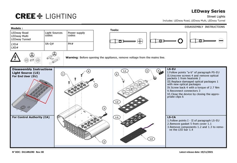
CREE LIGHTING SYRIUS SYS-A Series User manual

CREE LIGHTING

CREE LIGHTING SYRIUS SYS-A Series User manual

CREE LIGHTING SYRIUS User manual

CREE LIGHTING

CREE LIGHTING SYRIUS User manual

CREE LIGHTING LEDway Series Installation instructions

CREE LIGHTING

CREE LIGHTING LEDway Series Installation instructions

CREE LIGHTING OSQ Series User manual

CREE LIGHTING

CREE LIGHTING OSQ Series User manual

CREE LIGHTING EDGE ARE-EDG-R3 User manual

CREE LIGHTING

CREE LIGHTING EDGE ARE-EDG-R3 User manual

CREE LIGHTING IG Series User manual

CREE LIGHTING

CREE LIGHTING IG Series User manual

CREE LIGHTING XSP Series User manual

CREE LIGHTING

CREE LIGHTING XSP Series User manual

CREE LIGHTING IG Series User manual

CREE LIGHTING

CREE LIGHTING IG Series User manual

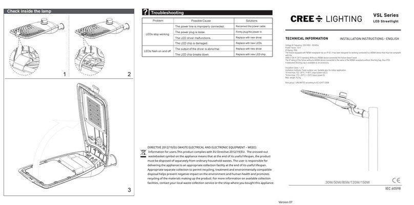
CREE LIGHTING VSL Series User manual

CREE LIGHTING

CREE LIGHTING VSL Series User manual
CREE LIGHTING EDGE Series User manual

CREE LIGHTING

CREE LIGHTING EDGE Series User manual

CREE LIGHTING XSP Series Installation instructions
CREE LIGHTING

CREE LIGHTING XSP Series Installation instructions

Popular Outdoor Light manuals by other brands

SImx WANAKA LHT1109 installation instructions

SImx

SImx WANAKA LHT1109 installation instructions

SLV VAP 40 operating manual

SLV

SLV VAP 40 operating manual

BEGA UniLink 84 824 Instructions for use

BEGA

BEGA UniLink 84 824 Instructions for use

Hornbach 10554557 Assembly instructions

Hornbach

Hornbach 10554557 Assembly instructions

Westinghouse W-431 owner's manual

Westinghouse

Westinghouse W-431 owner's manual

Gruppo Raina Lookup Utile Assembly instructions

Gruppo Raina

Gruppo Raina Lookup Utile Assembly instructions

Vaxcel T0080 Assembly and installation instructions

Vaxcel

Vaxcel T0080 Assembly and installation instructions

Sistemalux MINI LOOK instruction sheet

Sistemalux

Sistemalux MINI LOOK instruction sheet

oluce COUPE 3320R Mounting instructions

oluce

oluce COUPE 3320R Mounting instructions

Philips 172434716 user manual

Philips

Philips 172434716 user manual

LUCIDE ZORA LED quick start guide

LUCIDE

LUCIDE ZORA LED quick start guide

Beachside Lighting MB4 manual

Beachside Lighting

Beachside Lighting MB4 manual

GE Evolve R150 Series instructions

GE

GE Evolve R150 Series instructions

Inspire YKRS3F21WW-2 instruction manual

Inspire

Inspire YKRS3F21WW-2 instruction manual

Paul Neuhaus Q 831500 Fitting instructions

Paul Neuhaus

Paul Neuhaus Q 831500 Fitting instructions

Milwaukee FL-LED Original instructions

Milwaukee

Milwaukee FL-LED Original instructions

Springdale Lighting PT13270 Assembly instructions

Springdale Lighting

Springdale Lighting PT13270 Assembly instructions

Konstsmide 7529-750/EE Mounting instruction

Konstsmide

Konstsmide 7529-750/EE Mounting instruction

manuals.online logo
manuals.online logoBrands
  • About & Mission
  • Contact us
  • Privacy Policy
  • Terms and Conditions

Copyright 2025 Manuals.Online. All Rights Reserved.