manuals.online logo
Brands
  1. Home
  2. •
  3. Brands
  4. •
  5. Croplands
  6. •
  7. Farm Equipment
  8. •
  9. Croplands WEED-IT User manual

Croplands WEED-IT User manual

1
WWW.CROPLANDS.COM.AU
TRANSPORT,
UNLOADING &
SETUP GUIDE
STOP
BEFORE COMMENCING
operation, ENSURE you read
& understand this manual, its
contents, and any additional
information supplied.
BT-OMWEED-TRANS v4 Specifications subject to change without notice
BT-OMWEED-TRANS v4
2
Please read this guide, the Transport Kit
information, and Croplands Safety booklet
before unloading the WEED-IT sprayer.
Items required for assembly and set up.
• Suitable lifting equipment to remove
upper 6 metre boom tip from the transport
position, (approximate weight of the
6-metre boom is 500kgs).
• Tension wrenches capable of
800 Nm and 235Nm tension.
• Tyre inflation equipment and
pressure gauge to suit.
• WEEDit Transport Kit Information
sheet BT-OMWEED-MP375,
(2 pages - should be in the red
box with controllers etc).
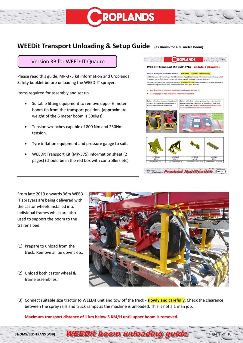
WEED-IT sprayers are delivered with the castor wheels
installed into individual frames which are also used to
support the boom to the trailer’s bed.
1. Prepare to unload from the truck. Remove all tie
downs etc.
2. Unload both castor wheel & frame assemblies
(yellow frame & content in adjacent picture).
3. Connect suitable size tractor to WEEDit unit and tow
off the truck - slowly and carefully. Check the
clearance between the spray rails and truck ramps as
the machine is unloaded. This is not a 1 man job.
Maximum transport distance of 1 km below
5 km/h until upper boom is removed.
4. Loosen hardware for the yellow transport stands that
are attaching the upper boom to the lower boom.
Place suitable lifting device under the boom, remove
the mounting hardware.
BOOM TRANSPORT, UNLOADING & SETUP GUIDE
VERSION 4
BT-OMWEED-MP375, (v4) 09/08/2021 P
P
R
R
O
O
D
D
U
U
C
C
T
T
I
I
N
N
F
F
O
O
R
R
M
M
A
A
T
T
I
I
O
O
N
N
Specifications subject to change without notice
WEEDit Transport Kit, (MP-375) – version 4
WEEDit Transport Brackets & Frames: Return to Croplands after delivery.
WEEDit Sprayers with booms longer than 28 metres are shipped double tiered with the outer castor wheels supplied
in separate frames. This requires a variety of brackets, braces & hardware, as per this document.
Customers are billed for the transport kit – which is refunded upon return of all components – all larger YELLOW
items on a pallet along with smaller items, plates and hardware in the spare red crate.
•Note: From time to time items supplied will vary from the standard transport kit.
•Use these pages to check off supplied & returned components.
•Steer (main) wheel shock absorbers are exchanged with rigid bars (HP-379-1) for truck transporting.
Versions shown below are for “RED” tech. QUADRO “BLUE” tech versions have some modification to the original parts.
extra pads used on Quadro
MP-371-1L
QTY: 1
MP-371-1R
QTY: 1
MP-371-3
QTY: 2
MP-371-2
QTY: 4
Use plate MP-371-2 Use plate MP-371-2
Mount to MP371-1L / 1R
Use with MP371-1L / 1R
Delivery will include the caster wheels bolted
to the MP-379 frames, and then used to
support the boom to the truck’s trailer.
Delivery includes shocks, controllers, manuals etc all wrapped to a
pallet along with a spare crate. Please use the pallet & spare crate
to ship the transport kit components back to Croplands. Boom
protection bars (pictured below) are usually fitted to the sprayer.
WWW.CROPLANDS.COM.AU
SAFETY
MANUAL
OPERATORS
STOP
BEFORE COMMENCING
operation, ENSURE you read
& understand this manual, its
contents, and any additional
information supplied.
GP-SAFE-A | Update 2
CLD5701_Croplands safety manual_update 2_2021.indd 1CLD5701_Croplands safety manual_update 2_2021.indd 1 19/1/21 3:00 pm19/1/21 3:00 pm
3
5. Raise the upper boom, slowly, making sure it clears the
structure below (note the left-hand side needs to clear
the 3 x vertical “bumper” bars). Once clear, tow the
WEEDit forwards and lower outer boom to a suitable
working height.
6. Remove front & rear transport stands.
Note these photos are
from an earlier model boom
& (unpainted) brackets.
All transport brackets
should be painted yellow.
IMPORTANT – be very
careful re stability, especially
as the support brackets are
removed. Ideally use slings
rather than fork tynes.
BT-OMWEED-TRANS v4
4
7. Reverse the WEEDit unit (or very carefully take outer
boom to the unit) to connect the booms together.
8. Join boom together. Add all of the bolts and washers
leave them loose to assist with the boom alignment.
Remove half of the bolts to
make joining easier. The bolts
may need to be loose to assist
with alignment of holes.
BOOM TRANSPORT, UNLOADING & SETUP GUIDE
VERSION 4
5
9. Fit all nuts and washers, adjust top outer bolts first to
get 1000mm spacing between the centre lines of the
cameras at the join point.
10. Swap out the yellow Steer wheel transport bars for the
supplied shock absorbers. Must use a jack or support
stand to prevent the boom dropping whilst performing
this task. Note the inner / “steer” wheel assembly
uses black coil springs, and the outer / “castor” wheel
assembly uses red coloured springs.
With the wheel still raised clear of the ground (see more
next page), add 80 psi to both shock absorbers.
Start with these 2 first
BT-OMWEED-TRANS v4
6
11. Fit outer castor wheels while outer boom is supported
by the forklift. Position between the last 2 WEEDit
sensors as per the diagram above. It’s the same for
36 or 30m boom. Note the pivot pin is to the front of
the main boom section - the mounting saddle plates
have been hidden for clarity of pin position.
12. With the wheel raised clear of the ground, add 80 psi
to both shock absorbers.
To protect the airbag, it’s vital the initial pressurisation
of the airbag is done with the wheel raised clear of
the ground.
Both shock absorbers in each set must be the
same pressure.
Fine adjustment will be done at a later stage (see
#22, page 10).
13. Set all boom tyre pressures to 15 psi. The boom can
now free stand.
14. Adjust the top inner bolts to align all camera brackets.
15. Adjust all 4 lower bolts to get the boom parallel to the
ground at the join point.
Tension all nuts to 800Nm.
BOOM TRANSPORT, UNLOADING & SETUP GUIDE
VERSION 4
7
16. Remove yellow inner pivot brace. Remember to return
all “Yellow” Transport kit components, including nuts,
bolts and washers to Croplands for credit.
Place all hardware and plates in the red crate in
preparation for return to Croplands along with all
“Yellow” items.
Collect and pack all “Yellow” items for return.
See the transport kit guide, BT-OMWEED-MP375.
BT-OMWEED-MP375, (v4)
09/08/2021 P
P
R
R
O
O
D
D
U
U
C
C
T
T
I
I
N
N
F
F
O
O
R
R
M
M
A
A
T
T
I
I
O
O
N
N
Specifications subject to change without notice
WEEDit Transport Kit, (MP-375) – version 4
WEEDit Transport Brackets & Frames: Return to Croplands after delivery.
WEEDit Sprayers with booms longer than 28metres are shippe d double tiered with the outer castor wheelssuppli ed
in separate frames. This requires a variety of brackets, braces & hardware, as per this document.
Customers are billed for the transport kit – which is refunded upon return of all components – all larger YELLOW
items on a pallet along with smaller items, plates and hardware in the spare red crate.
•Note: From time to time items supplied will vary from the standard transport kit.
•Use these pages to check off supplied & returned components.
•Steer (main) wheel shock absorbers are exchanged with rigid bars (HP-379-1) for truck transporting.
Versions shown below are for “RED” tech. QUADRO“BLUE” tech versions have some modification to the original parts.
extra pads used on Quadro
MP-371-1L
QTY: 1
MP-371-1R
QTY: 1
MP-371-3
QTY: 2
MP-371-2
QTY: 4
Use plate MP-371-2 Use plate MP-371-2
Mount to MP371-1L / 1R
Use with MP371-1L / 1R
Delivery will include the caster wheels bolted
to the MP-379 frames, and then used to
support the boom to the truck’s trailer.
Delivery includes shocks, controllers, manuals etc all wrapped to a
pallet along with a spare crate. Please use the pallet & spare crate
to ship the transport kit componentsback to Croplands. Boom
protection bars (pictured below) are usually fitted to the sprayer.
BT-OMWEED-TRANS v4
8
17. Connect all spray lines (spot, blanket (if applicable)
and fence line) and all WEED-IT / electrical
connections between the main boom and tip sections.
18. Fit boom bumper bars (if not
fitted at the time of delivery).
Normally the one-piece
Horizontal Bump bar is fitted
to the left-hand boom, and the
3 single Vertical Bump arms
are fitted to the right-hand
side. The photos below show
fitment to the opposite sides.
Preferred Bumper bar position
for 36m boom is on the
“intermediate” arm (as shown
at bottom). Shorter booms will
require the bump guards to be
mounting on the inner arm.
BOOM TRANSPORT, UNLOADING & SETUP GUIDE
VERSION 4
9
19. Fit and connect all controllers to the tractor as per the
operator’s manuals supplied with each controller.
20. Connect all electrical and hydraulic fittings between
the tractor and WEEDit unit.
21. Adjust WEEDit chassis air bag ride height valve until
the first WEEDit sensor on the boom is near 1100mm
from the ground to lens of the sensor, (system needs to
be powered up / air compressor working).
CAUTION
!
Other factors such as drawbar height (either side of
450mm), tyre pressures (sprayer & boom) and airbag
pressures will also influence this height. Fine tune
sensor heights at the completion of the install.
BT-OMWEED-TRANS v4
10
22. Set boom airbag heights.
• Note this should only be done with the sprayer
on flat ground and the boom open to the spray
position. Use the quick start folding guide BT-
OMWEED-QSG-B to fold the boom out to the
working position
• With the boom in the working position, slowly
release air evenly from both shockers (at this stage
the airbags should have 80 psi) to achieve a
camera working height of 1100 mm.
• There needs to be always a minimum of 20psi in
the shocker!
• Both shockers in each set must be the same
pressure
23. Tension boom wheel bolts to a minimum of 235Nm
(173 ft.lbs.)
WEEDit – Boom Parking, Quick Start Guide (v3), to suit the 4 + 5 switchbox.
It’s vital that the correct
parking procedures are
followed.
Failure to follow these
guidelines may result in
damage to the sprayer.
Perform all folding
operations on flat ground.
LH and RH Fence-line switching is via
the same switchbox. Down is OFF.
TO OPEN THE WEEDit BOOM, ready to spray >>>
1. Hold the LATCH ARMS switch DOWN to set the latches to the Lock position.Check the locking
rams are retracted.
2. Fully extended both stay arms. Hold the FOLD ARM switch to the DOWN position until both
sides are fully extended.
3. Set the BOOM STEER WHEELS switch to PART FOLD, this will only allow the boom wheels
to rotate ½ of their travel.
4. Drive forwards slowly below 5 KM/H. While moving forward, hold both the LH WHEEL &RH WHEEL
switches DOWN, this will allow the booms to move approximately out half way
•It will take approximately take 10 ~ 30 metres of travel to accomplish
this, depending on the soil conditions.
•Set the BOOM WHEELS switch back to the LOCK position.
Rotate the main wheels back to the original position, so they are in-line with the
boom. Hold both the LH WHEEL & RH WHEEL switches to the UP position until done.
PTO
BOOM TRANSPORT, UNLOADING & SETUP GUIDE
VERSION 4
11
24. The boom steering wheels have a “tracking” bolts which will require adjustment.
The wheels should have a small amount of toe out when travelling forward to keep
the booms apart when cornering. Set the boom to the transport position and drive
forward slowly, there should be a minimum of 200 mm clearance between the
bumper bars, rotate the top steer wheel stop bolt out to increase the clearance
between the boom “bumper” bars, check that one side is not wider at the rear than
the other side.
This stop bolt is used to align the
“Steer” wheel in the road travel/
transport position.
This is the old position for the boom bumpers
– correct (v2) position is on the intermediate
section, closer to the tip.
Correctly set up boom
This picture is an example of an incorrectly
adjusted boom. The left boom is too wide; Rotate
the top bolt in half a turn on the left boom and test.
BT-OMWEED-TRANS v4
12
25. Adjust the drawbar to achieve 1100mm camera
height on the central cameras – as a guide, the main
chassis sits approximately 6 degrees nose down from
horizontal, and the upright tank supports are
90 degrees from horizontal, when correctly adjusted.
Note this will also influence the boom ride height (see #21).
Use a spirit level to get tank level bar
horizontal. Adjust the rear WEEDit
drawbar to achieve this.
BOOM TRANSPORT, UNLOADING & SETUP GUIDE
VERSION 4
13
Before operating, please read the Boom
Parking Quick Start Guide, BT-OMWEED-
QSG-B (version 3), as shown here.
Carry out the set up and pre-delivery of the machine using
the supplied manuals for the WEEDit system and blanket
spray line (if equipped) using the supplied manuals.
WEEDit – Boom Parking, Quick Start Guide (v3), to suit the 4 + 5 switchbox.
It’s vital that the correct
parking procedures are
followed.
Failure to follow these
guidelines may result in
damage to the sprayer.
Perform all folding
operations on flat ground.
LH and RH Fence-line switching is via
the same switchbox. Down is OFF.
TO OPEN THE WEEDit BOOM, ready to spray >>>
1. Hold the LATCH ARMS switch DOWN to set the latches to the Lock position.Check the locking
rams are retracted.
2. Fully extended both stay arms. Hold the FOLD ARM switch to the DOWN position until both
sides are fully extended.
3. Set the BOOM STEER WHEELS switch to PART FOLD, this will only allow the boom wheels
to rotate ½ of their travel.
4. Drive forwards slowly below 5 KM/H. While moving forward, hold both the LH WHEEL &RH WHEEL
switches DOWN, this will allow the booms to move approximately out half way
•It will take approximately take 10 ~ 30 metres of travel to accomplish
this, depending on the soil conditions.
•Set the BOOM WHEELS switch back to the LOCK position.
Rotate the main wheels back to the original position, so they are in-line with the
boom. Hold both the LH WHEEL & RH WHEEL switches to the UP position until done.
PTO
BT-OMWEED-QSG-B WEEDit Boom Parking: Quick Start Guide (v3) Page 2of 2
5. Reverse slowly until the booms arms have opened all the way
and the fold arms have latched into the locks.
•If one side latches before the other side use the wheel
switch to rotate the wheel to the field position to prevent
the wheels from bulldozing.
•It may take around 10 metres of travel to accomplish this,
depending on the soil conditions.
•Do not continue to reverse with wheels in this position.
•Double check that both stay arms are docked & locked.
6. Rotate both main wheels “outwards” 90 degrees, to now point forwards in the
direction of spray travel. Hold both the LH WHEEL & RH WHEEL switches to the DOWN
position, and at the same time slowly move forwards until done (a few seconds).
7. Spray mode:Set the BOOM WHEELS switch to SPRAY position.
This will allow the boom wheels to float when turning. Go spraying.
TO FOLD THE WEEDit BOOM >>> All folding operations should be on flat ground
1. Lock the wheels (facing direction of travel). Set the BOOM WHEEL switch to LOCK .
2. Unlock the arms. Move the LATCH ARMS switch UP to UNLOCK.
3. Drive forwards slowly below 5 KM/H. While moving forward, hold both the LH WHEEL &RH WHEEL
switches UP, this will move the wheels into the transport position (in line with
the boom). Travel forwards slowly until both booms are trailed behind the sprayer.
4. Fold in both stay arms. Hold the FOLD ARM switch to the IN position until both sides are fully
retracted. Only fold the arms in when the booms are fully folded together to
avoid damage to mudguards.
5. Set up the machine for safe transport (also see Transport, unloading & setup guide). Remain in “Lock”.
NOTE
Never operate the boom when
the wheels are at right angles
to the direction of travel.
NOTE
Be very careful to follow the (manual)
instructions for setting up the boom stay arms
(it’s a little counter intuitive and easy to get
wrong if not following instructions).
CROPLANDS
AUSTRALIA
Croplands Equipment Pty Ltd
ACN 006 450 184
PO Box 2441
Dry Creek
50 Cavan Road
Dry Creek SA 5094
Australia
Freecall: 1800 999 162
Freefax: 1800 623 778
Email: [email protected]
Website: www.croplands.com.au
NEW ZEALAND
Croplands Equipment Ltd
PO Box 2004,
Stortford Bridge, Hastings 4120
Location:
1422 Omahu Road,
Hastings 4120
New Zealand
Freecall: 0800 106 898
Freefax: 0800 117 711
Email: [email protected]
Website: www.croplands.co.nz
CANADA
Croplands Equipment Pty Ltd
PO Box 2441
Dry Creek, SA 5094
Australia
Phone +1403-831-3913
Email address:
[email protected]
www.croplands.com.au
Your nearest Croplands Dealer
can be found in the dealer section
on the Croplands website

Other manuals for WEED-IT

1

Other Croplands Farm Equipment manuals

Croplands PEGASUS 8000 User manual

Croplands

Croplands PEGASUS 8000 User manual

Croplands WEED-IT Quadro User manual

Croplands

Croplands WEED-IT Quadro User manual

Croplands XR11001 AI11001 User manual

Croplands

Croplands XR11001 AI11001 User manual

Croplands Quantum Mist QM-500 User manual

Croplands

Croplands Quantum Mist QM-500 User manual

Croplands US20F/252/HR30 User manual

Croplands

Croplands US20F/252/HR30 User manual

Croplands Cropliner 1500XL User manual

Croplands

Croplands Cropliner 1500XL User manual

Croplands PEGASUS 4000 User manual

Croplands

Croplands PEGASUS 4000 User manual

Croplands QUANTUM FUSION User manual

Croplands

Croplands QUANTUM FUSION User manual

Croplands AgriPak LA300 User manual

Croplands

Croplands AgriPak LA300 User manual

Croplands US200C/25/100R3 User manual

Croplands

Croplands US200C/25/100R3 User manual

Croplands CROPAIR 300 User manual

Croplands

Croplands CROPAIR 300 User manual

Croplands WEED-IT Quadro User manual

Croplands

Croplands WEED-IT Quadro User manual

Croplands WEED-IT Quadro User manual

Croplands

Croplands WEED-IT Quadro User manual

Croplands PEGASUS 8000 Programming manual

Croplands

Croplands PEGASUS 8000 Programming manual

Croplands PEGASUS 7000 Standard User manual

Croplands

Croplands PEGASUS 7000 Standard User manual

Popular Farm Equipment manuals by other brands

AEC GP1200 Series Operation and installation manual

AEC

AEC GP1200 Series Operation and installation manual

Falcon F25/90 Operator's manual

Falcon

Falcon F25/90 Operator's manual

Raven SmarTrax MD installation manual

Raven

Raven SmarTrax MD installation manual

Enoitalia DELTA 1 User Instructions, Installation and Technical Manual

Enoitalia

Enoitalia DELTA 1 User Instructions, Installation and Technical Manual

Boumatic Flo-Star Liner Cap Assembly instructions

Boumatic

Boumatic Flo-Star Liner Cap Assembly instructions

Cima New Plus Maintenance Instruction

Cima

Cima New Plus Maintenance Instruction

Degelman Signature 6000 manual

Degelman

Degelman Signature 6000 manual

STEELGREEN SG36 instruction manual

STEELGREEN

STEELGREEN SG36 instruction manual

BROWN BDHP900 Owner's/operator's manual

BROWN

BROWN BDHP900 Owner's/operator's manual

SIP STAR 430/12V Instruction for work

SIP

SIP STAR 430/12V Instruction for work

Amazone Limiter M Fitting instructions and setting

Amazone

Amazone Limiter M Fitting instructions and setting

Classen HTS-20HE Operator's manual

Classen

Classen HTS-20HE Operator's manual

Amazone TL 3000 instruction manual

Amazone

Amazone TL 3000 instruction manual

Degelman STRAWMASTER 50 Operator's & parts manual

Degelman

Degelman STRAWMASTER 50 Operator's & parts manual

SEEDMASTER ULTRA SR Operator's manual

SEEDMASTER

SEEDMASTER ULTRA SR Operator's manual

Worksaver FLGR-4062 Operator's manual

Worksaver

Worksaver FLGR-4062 Operator's manual

Fliegl ULW operating instructions

Fliegl

Fliegl ULW operating instructions

Alice's Garden GALINETTE manual

Alice's Garden

Alice's Garden GALINETTE manual

manuals.online logo
manuals.online logoBrands
  • About & Mission
  • Contact us
  • Privacy Policy
  • Terms and Conditions

Copyright 2025 Manuals.Online. All Rights Reserved.