Croydex WC410122 User manual

This manual suits for next models
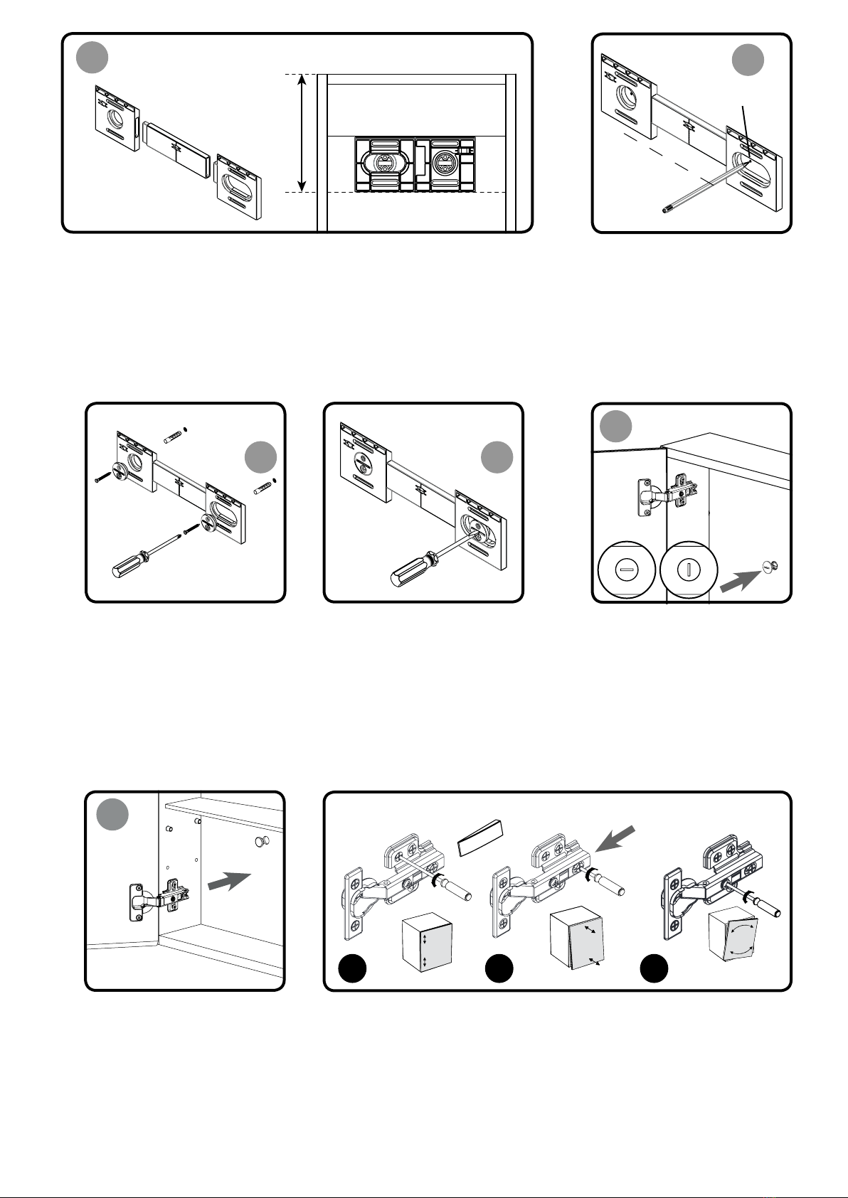
1
Table of contents
Other Croydex Indoor Furnishing manuals

Croydex
Croydex MM720200E User manual

Croydex
Croydex WC9300 Series User manual

Croydex
Croydex Flexi-Fix 1919 User manual

Croydex
Croydex AP130422 User manual

Croydex
Croydex WS040478 User manual

Croydex
Croydex WC101169 User manual

Croydex
Croydex Triple Corner Basket Set User manual

Croydex
Croydex QA200021 User manual

Croydex
Croydex WC216105 User manual

Croydex
Croydex WS010522 User manual

Croydex
Croydex MM703000E User manual

Croydex
Croydex AD149641 User manual

Croydex
Croydex WC257122 User manual

Croydex
Croydex AP400522 User manual

Croydex
Croydex Anton WC736005 Installation guide

Croydex
Croydex Flexi-Fix QA2010 Series User manual

Croydex
Croydex WC102122 User manual

Croydex
Croydex WC450505 Manual

Croydex
Croydex Boston WS010122 User manual

Croydex
Croydex WC257122 User manual


Popular Indoor Furnishing manuals by other brands

Next
Next WESTCOTT 127530 Assembly instructions

Mocka
Mocka Alice Bar Cart Assembly instructions

Whittier Wood
Whittier Wood 1859GBCHb Assembly instructions

DURAVIT
DURAVIT XViu XV 7045 Mounting instructions

Woodard
Woodard FS RXTV-1822-CT Assembly instructions

Casa Lusso
Casa Lusso FCAB-600 installation instructions

Rauch
Rauch Carlsson 28238.2530 Assembly instructions

Gami
Gami J36-TOSCANE installation instructions

Julian Bowen
Julian Bowen Jupiter JUP302 Assembly instructions

SMART
SMART FSE-420 user guide

Burgess
Burgess Tabou Table Handling, operation & maintenance manual

Möbelix
Möbelix MDIK211R Assembling Instruction


