CTEK E-MOBILITY CHARGESTORM Connected User manual

Installation manual CHARGESTORM® Connected
1Introduction
This document shows how to install and use the charge station CHARGESTORM® Connected.
Figure 1 CHARGESTORM® Connected
1) Front panel
2) Display with charging status symbols
3) Back cover
4) Technical box
5) EV connector (outlet or cable)
The manual is valid for the CHARGESTORM® Connected family. Model information is found on the
top of the technical box. For a complete list of article numbers, please download datasheet at
www.ctekemobility.com.
2Safety
✓Only accredited electrician is allowed to perform the installation described in this document
✓Read and follow the instructions in this document before installation and usage of the product
✓Installation must fulfill local safety regulations
3Delivery content
Part of delivery
✓Charging station
✓Installation and user manual
✓Two keys for opening CHARGESTORM® Connected
✓Cover for cable inlet (M32 and M12).
✓Holder for charging gun (In case charging station is equipped with fixed cable)
To bring
✓4 pcs screws (M8) for wall mounting. Select screw type depending of wall.
✓4 pcs of rubber seal/gaskets to use with screw. –Note very important!
✓RFID-tag (in case RFID shall be used) of type Mifare Classic/ IEC 14443 Type A. RFID-tags can
be ordered from CTEK E-Mobility web-shop (www.ctekemobility.com).
Option
✓CHARGESTORM® Connected pole mount kit for pole diameter 60 mm. Article number 920-
00010.

Installation manual CHARGESTORM® Connected page 2
✓CHARGESTORM® Connected pole mount kit for two CHARGESTORM® Connected boxes,
enabling up to four EV connectors from one pole. Article number 922-00018.
4Precondition
4.1 Tools
Before the installation make sure that following tools are available:
✓Screwdriver
✓Drilling machine
✓Multi meter
✓Computer (for network configuration)
✓Peeler
✓Mini USB cable (to connect computer and controller board)
✓Spirit level
✓Mifare Classic/ IEC 14443 Type A, compatible RFID-tag.
✓Computer/Laptop (OS: Linux or OSX preferred, Windows10 requires USB-driver
installation)
4.2 Cable installation
Before the installation of the charging station, control the following:
✓The cable installation is dimensioned for the charging station. (at least 2,5 mm2cable area
for 16A copper cable and at least 6mm2for 32A copper cable). For wall mounting shall 50
cm cable be available for use inside CHARGESTORM® Connected.
✓Make sure that power is off during installation
4.3 Network connection
In case CHARGESTORM® Connected shall be connected to a portal or a local controller, check the
following depending on network access medium:
✓3G: Activated SIM-card must be mounted in
CHARGESTORM® Connected with PIN disabled. The
subscription shall allow at least 2GB/month.
✓Ethernet: Network cable of type Cat5 or better shall be
connected to CHARGESTORM® Connected.
In case CHARGESTORM® Connected is behind a firewall and shall
be connected to a backend system must DNS (port 53), https/wss
(port 443) be opened in the firewall. If remote firmware upgrade
shall be possible must also ftp be opened in the firewall.
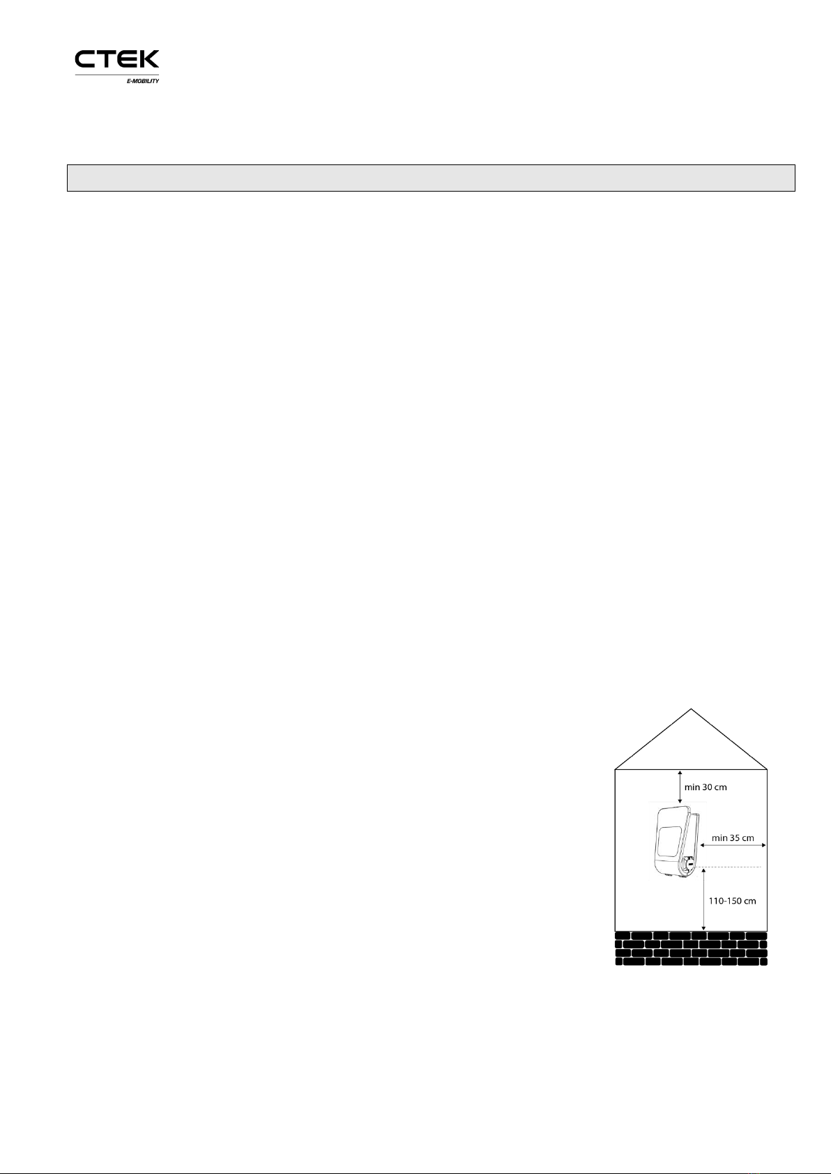
4.4 Installation location
Control the following at the location where CHARGESTORM®
Connected will be mounted:
✓That there is enough space available for normal usage.
✓That the wall material is suitable for mounting of
CHARGESTORM® Connected. The wall must withstand the
charging station weight (8,5kg)
Figure 2 CHARGESTORM®
Connected mounting distances

Installation manual CHARGESTORM® Connected page 3
✓Avoid installing CHARGESTORM® Connected in direct light sunlight. Symbol visibility is
limited and heat in the unit is increasing. CHARGESTORM® Connected has a temperature
sensor in the unit that adjust charging current in case of high temperature.
✓Always follow local regulation

Installation manual CHARGESTORM® Connected page 4
5Installation
Step 1) Unpack CHARGESTORM® Connected –Unpack
CHARGESTORM® Connected and all parts from the cardboard
box.
Step 2) Drill holes in the wall –Decide mounting position on
the wall. Drill four holes according to drawing, see Figure 4.
Step 3) Decide input location for power and network
1
–
Power and network cable can either be connected from the top
or the bottom. If cables are inserted from below must holes be
drilled in the unit according to Figure 3. It is strongly advised
that power cable is coming from below for outdoor installation,
avoiding any problems with water entering the unit from the
top along the cable during rain.
When cables are connected from the top: There are two holes
on the top. The largest 2. (M32) is for power while the smaller
1. (M12) is for network see Figure 5. The cable gland for 1. that
is delivered with the product supports cable dimensions
between12-22mm while the gland for 2. supports 3-6mm. The glands must be replaced if the cables
are outside specified range. If CHARGESTORM® Connected shall be part of a load balancing
installation or be connected to the backend via Ethernet must a network cable be connected to the
controller board RJ45 port. Cable glands shall be used to protect for dust and water penetration.
More information related to load balancing is available in, ref. 2) and ref. 3). If wiring is connected
from below must holes be drilled in the unit according to Figure 3.
Figure 5 Cable glands for incoming cables
Step 4) Wall mount CHARGESTORM® Connected –Unlock and open CHARGESTORM®
Connected with the key. Locate the four screwing holes in the back cover. M8 screw with at least t
1
For three-phase CHARGESTORM® Connected models with dual connectors power cable must
enter from below. Further, these CHARGESTORM® Connected models support 16mm2cable area.
Figure 3 Hole distances
Figure 4 Drill location

Installation manual CHARGESTORM® Connected page 5
40 mm length is recommended. Place CHARGESTORM® Connected on selected wall position and
fastened the unit with the four screws. Control that CHARGESTORM® Connected is firmly mounted
on the wall.
Figure 6 Open front cover with the key and fasten the unit on the wall
Step 5) Connect incoming power
2
-Pull the power cable through the cable gland about 450 mm. Peal the
wires about 8mm at the end. The wires cross section area must not exceed 16mm2. Make sure protected
ground wire is longer than the other wires sot that it will be the last wire to detach if pulled. Connect the
supply wires to the terminal blocks. Check that L1-L3, PE and N is correctly mated between female and
male connector. Put back protection cover and close and lock CHARGESTORM® Connected with the
key.
2
For three-phase CHARGESTORM® Connected models with dual connectors is incoming power
connected to the DIN rail mounted terminal blocks at the bottom between the connectors. Check
that L1-L3, PE and N is correctly mated. For schematics see chapter 11.

Installation manual CHARGESTORM® Connected page 6
Figure 7 Cable schematics
Cables inside CHARGESTORM® Connected for the supply wires from top
to terminal blocks shall follow the black line while supply wires from the
bottom shall follow the grey line in Figure 7.
Figure 8 Terminal blocks marking
Step 5.1) Only for IT-Nett: Install the CHARGESTORM® Connected according to Figure 9 or 10. L2
will be the return path in both the 1-phase and 2-phase installation.
Step 6) Connect network –In case Ethernet is used connect cable to RJ45-connector on the
control board located on the front panel. When cable is connected in both ends shall link and
activity led on the RJ45 connector be active. If 3G is in use, check that the SIM-card is installed on
the modem unit on the control board. Also check that the antenna cable is attached in both ends.
See schematics in chapter 11.
Step 7) Test –Activate power from the distribution panel, after closing and locking
CHARGESTORM® Connected with the key. Do not forget to put the cover on the key-lock. Green
connector symbol shall be active on the front panel after turning on power. Follow directives in
chapter 8.
Figure 9 1-Phase IT-Nett
installation
Figure 10 2-Phase IT-Nett
installation

Installation manual CHARGESTORM® Connected page 7
Figure 9 CHARGESTORM® Connected symbols.
Models with double outlets have two rows of
symbols
Display symbols
CHARGESTORM® Connected
available for charging
CHARGESTORM® Connected in
use. Fixed blue light when connected.
Pulsing blue light when charging.
RFID- Green –waiting for tag,
blinking yellow –checking tag,
blinking green –tag approved,
blinking red - tag denied
Out of order.
6Provisioning
When the electrical and network installation is ready shall CHARGESTORM® Connected be
configured for operational use (such as network configuration and portal configuration). The Portal
is a software that is used for remote operation and maintenance of CHARGESTORM® Connected. To
configure the CHARGESTORM® Connected control board through the local web interface is a mini
USB cable required. The mini-USB port is located on the control board while a standard USB port is
used on the computer for configuration. If the computer is running Microsoft Windows must an
Ethernet to USB-driver be installed to support access to the local web interface. For Linux and Mac
OSX is the driver part of the operating system. For detailed description of the local web interface
see ref. 1)
CTEK E-Mobility recommends that the installation technician documents the result of the
provisioning tests in a dedicated protocol.
Perform the following step to complete CHARGESTORM® Connected configuration.
1. Log in to the local web interface. URL: http://192.168.7.2 with user name ccu and password
ccu. All modern web browsers work but Chrome is recommended.
2. Configure network interface (Ethernet or 3G) so that internet access is available
3. Configure URL and charging station identity (ChargeboxId) to portal
4. Configure usage of RFID
5. Configure load balancing
6.1 Local web interface
To connect to the local web interface shall a USB cable be connected between the computer and
CHARGESTORM® Connected controller board mini USB port. In your browser enter IP address

Installation manual CHARGESTORM® Connected page 8
192.168.7.2 to reach the web interface. The log in page is shown after entering the address. To log
in enter:
Username: ccu
Password: ccu
Figure 10 Log in page
6.2 Network settings
After successful log in, is the network settings found under Configuration →interfaces
When network configuration is ready check on the status page that internet access is established.
Ethernet
To set the IP settings for Ethernet follow the instruction below.
•Under “Configuration→Interface→General”, select WAN=”Wire”.
•Under “Configuration→Interface→Wire”, select “DHCP”or “Static”(for Static enter IP
address, netmask and gateway). For “DHCP” is IP address assigned automatically.
•Push the “Save” button on the bottom of the page.
Figure 11 Ethernet configuration

Installation manual CHARGESTORM® Connected page 9
PPP modem
Follow the step by step instruction below to configure PPP over 3G
•Under “Configuration→Interface→General”, select WAN=”Wireless”
•Under “Configuration→Interface→PPP modem”, enter “APN”applicable for the selected 3G
operator. Remaining fields can usually be left empty.
•Push the “save” button (at the bottom of the page).
Figure 12 3G Configuration
WWAN modem
WWAN is a specific 3G-mode. WWAN tends to be more robust than PPP described in previous chapter.
Follow the step by step instruction to configure WWAN.
•Under “Configuration→Interface→General”, select WAN=”Wireless”
•Under “Configuration→Interface→WWAN”, enter “APN”applicable for the selected 3G
operator. Remaining fields can usually be left empty.
•Push the “save” button (at the bottom of the page).
6.3 Current limit
From the local web interface is the max current limit configured (in case the limit shall be lower
than the charging status fuse level). Under configuration outlet, see Figure 13 is the current limit
set.

Installation manual CHARGESTORM® Connected page 10
Figure 13 Configuration of current limit
6.4 Portal access
Portal configuration connection requires that the internet access is working. The OCPP chargeboxid
and server address must be known in advance in order to connect CHARGESTORM® Connected to
the portal. The information shall be provided by the portal operator. In case the CTEK E-Mobility
portal “Charge Portal” is used is the URL to the portal on the following format.
wss://<companyname>.oamportal.com/Ocpp/websocket Chargeboxid must not contain more than
22 characters and it must be unique (charging stations cannot have the same chargeboxid).
CHARGESTORM® Connected uses OCPP v1.5 or v1.6, which must be supported by the selected
portal.
•Select ”Configuration→Server”and enter the ”ChargeboxId”
•Select communication protocol to OCPP v1.5 or OCPP v1.6.
•Enter server address. Most often can the other parameters remain unchanged.
•Push the “Save” button (on the bottom of the page)
After completing the configuration navigate to the status page and verify that the portal
communication is established.
Figure 14 Portal configuration

Installation manual CHARGESTORM® Connected page 11
6.5 RFID
In order to activate user authentication can RFID be used. RFID-configuration can either take place
from the portal (from a browser) or be configured on local web interface.
•To activate RFID, navigate to ”Configuration→Outlet→Authentication”and select ”RFID” for
all outlets. This setting will require user to authenticate with RFID tag before charging starts.
Figure 15 Outlet in RFID-mode
•It is possible in ”Tag administration”to add and delete RFID-tags that shall be activated on
CHARGESTORM® Connected.
7Product information
Power input
Power
16-32A, 230V, 1-phase or 16-32A, 400V, 3-phase, 50Hz. Power input
connector depends on model.
Charging current
16-32A
Supply Connection
L1,L2,L3,N,PE. Cable area 2,5 –16mm2.
(For IT-Nett: L1,L2,L3,PE Cable area 2,5 –16mm2.. )
Fuses
C-characteristics. Type A. Breaking capacity 6kA. Nominal current 16 or
32A depending on model.
Mechanics
Weight
Less than 12kg (depends on model)
Dimension
Height: 395mm, Width: 278mm, Depth: 160mm
Material
Front and back cover in ABS plastic. Colored zinc oxide metal box for
electronics.
IP
44
Temperature
-25°C - +50°C
Interfaces
EV connector
1 or 2 outlets Type 2 or fixed cable of Type 1 or Type 2

Installation manual CHARGESTORM® Connected page 12
Schuko
1 pc Schuko-outlet CEE 7/3 (on some models)
Display
LED-light symbols
Lock
Mechanical lock with key.
Energy meter
MID-approved energy meter. (on some models)
RFID
Mifare Classic RFID-reader. Frequency 13.56MHz, Magnetic
field +42 dBµA/m (ETSI EN 300 330 V2.1.1)
3G Option
Frequency band: 800/850/900/1700/1800/1900/2100 MHz
Power class 3: +24 dBm, Power class 4: +21 dBm (EN 301 908-2 v11.1.1)
Compatibility
Standards
IEC 61851-1, IEC 62192-2, IEC 61439-1:2011
Approval
CE. Declaration of Conformity can be downloaded from
www.ctekemobility.com
Safety
Ground fault
detector
Model dependent. Ground fault detector of type and DC-detector.
8Installation and maintenance tests
Preventive maintenance of CHARGESTORM® Connected shall be conducted at least once per year.
At installation and maintenance of CHARGESTORM® Connected shall the following tests be
performed.
Test:
✓Trip ground circuit breaker. Use test button on breaker.
✓Control power cables (and re-tighten cables when needed).
✓Control that charging outlet /cable is in good condition. Replace otherwise.
✓Check gaskets. Remove dirt if needed
✓Charge a vehicle. Check current and that charging symbols on display are working.
✓Update software if needed
✓Control network access to back end (in case CHARGESTORM® Connected is connected)
9Recycling
CHARGESTORM® Connected contains electronics and shall be recycled. You can send back
CHARGESTORM® Connected to CTEK E-Mobility Center and we will take care of the recycling.
Alternatively, follow your local guide for recycling of electronics.
10 Warranty
Warranty period for CHARGESTORM® Connected is 1 year from delivery to customer.

Installation manual CHARGESTORM® Connected page 13
11 Electrical schematics
11.13-phase
Below is an example of a schematics for CHARGESTORM® Connected (3ph dual outlet).

Installation manual CHARGESTORM® Connected page 14
11.1 IT-nett
Below is an example of a schematics for CHARGESTORM® Connected (1ph dual outlet, IT-nett).

Installation manual CHARGESTORM® Connected page 15
12 General
12.1References
Id Tit Dokument Id
1) CCU configuration manual Pd_CM_002
2) CGC Installation manual Pd_IM_0007
3) Home load balancing manual Pd_IM_0012
12.2Copyright
This manual is delivered “as is” and contain content that can change without prior notice. CTEK E-
Mobility does not guarantee that everything is correct in the manual. CTEK E-Mobility is not responsible
for faults or incidents or damages that can be traced to the usage of this manual.
© Copyright CTEK E-Mobility. All rights restricted. copying, adaption, or translation of this manual is
strictly forbidden without written approval by CTEK E-Mobility, except what is regulated by copyright
laws.
12.3Contact information
CTEK E-Mobility Center
Malmgatan 4
SE-602 23 Norrkoping, Sweden
Phone: +46 11 333 0002 • Fax +46 11 333 0003
Email: [email protected]
Document number: Pd_IM_0011, version A.13
Article number: 720-00008
Table of contents
Other CTEK Batteries Charger manuals

CTEK
CTEK D250SA User manual

CTEK
CTEK MXS 5.0 User manual

CTEK
CTEK MULTI XS 4003 1035 User manual

CTEK
CTEK HOME LOAD BALANCING WITH CHARGESTORM CONNECTED... User manual

CTEK
CTEK 1087 User manual

CTEK
CTEK POWERSPORT User manual

CTEK
CTEK PRO25S User manual

CTEK
CTEK MXS 8.0 User manual

CTEK
CTEK US 800 User manual

CTEK
CTEK Multi XS 7000 User manual

CTEK
CTEK MXTS 40 User manual

CTEK
CTEK SMARTPASS 120S User manual

CTEK
CTEK 20016111A MXS 10 User manual

CTEK
CTEK MULTI XT 4000 Series Assembly instructions

CTEK
CTEK MULTI US 3300 User manual

CTEK
CTEK MXS 10 User manual

CTEK
CTEK M200 User manual

CTEK
CTEK MUS 4.3 POLAR User manual

CTEK
CTEK CHARGESTORM CONNECTED 2 User manual

CTEK
CTEK 1055 User manual