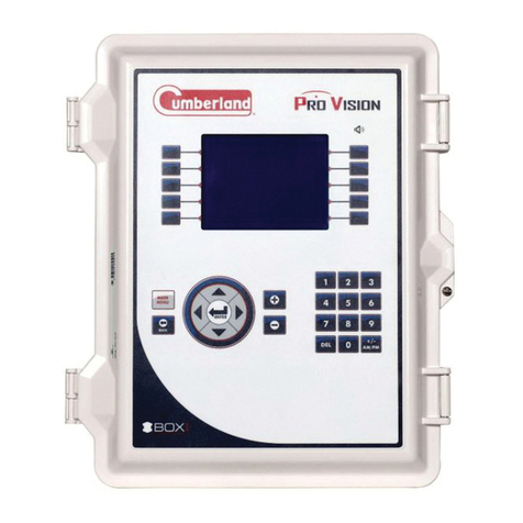
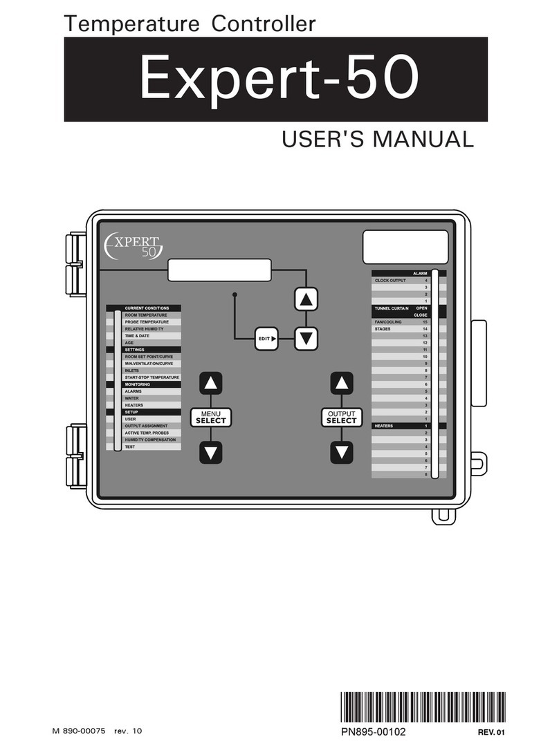
Cumberland Expert-32P User manual

Expert-32P
Temperature Controller
USER'S MANUAL

2Expert-32P rev.11
TABLE OF CONTENTS
Page
PRECAUTIONS ........................................................................... 3
FEATURES ................................................................................. 4
LOCATION OF THE CONTROLS ................................................... 7
INSTALLATION .......................................................................... 9
Mounting Instructions ................................................................ 9
Connections ............................................................................. 9
CONTROLLER SETUP ................................................................ 12
Brooding / Grow Out / Clean Mode Setup .................................... 12
User Setup ............................................................................ 12
Relay Assignments .................................................................. 17
Probe Assignments ................................................................. 20
TEMPERATURE SETTINGS ......................................................... 21
Viewing Temperatures ............................................................. 21
Temperature Set Points ........................................................... 24
Temperature Curve ................................................................. 26
TIME AND DATE ...................................................................... 28
MINIMUM VENTILATION ........................................................... 29
Principle of Operation .............................................................. 29
Minimum Ventilation Curve ....................................................... 31
HUMIDITY CONTROL ................................................................ 33
HEATER SETTINGS ................................................................... 36
FAN SETTINGS ........................................................................ 38
COOLING ................................................................................ 41
TUNNEL VENTILATION .............................................................. 43
Curtain: moving times based on the stages' activation ................... 43
Curtain: based on the static pressure .......................................... 44
VENT DOORS ........................................................................... 51
AIR INLET CONTROL ................................................................. 56
CLOCK OUTPUTS ..................................................................... 57
ALARM SETTINGS.................................................................... 59
MONITORING FUNCTIONS ......................................................... 64
CLEAN MODE .......................................................................... 66
TEST MODE ............................................................................. 68
TECHNICAL SPECIFICATIONS .................................................... 69
FACTORY SETTINGS ................................................................ 70

3
Expert-32P rev.11
We strongly recommend installing supplementary ventilation as
well as a backup thermostat on at least one fan stage (refer to
the wiring diagram enclosed with this user's manual to connect
the thermostat).
Although overload and overvoltage protection is provided for the
controller circuits, we recommend installing additional protec-
tion devices in the electrical panel.
The room temperature where the controller is located MUST
ALWAYS REMAIN BETWEEN 32°F AND 104°F (0°C TO
40°C).
To avoid exposing the controller to harmful gases or excessive
humidity, it is preferable to install it in a corridor.
DO NOT SPRAY WATER ON THE CONTROLLER
PRECAUTIONS
FORCUSTOMERUSE
Enter the serial number located on
the side of the controller below for
future reference.
Model number:
Serial number:
Expert-32P

4Expert-32P rev.11
The Expert-32P is an electronic device used for environmental control in
livestock buildings. It allows the user to maintain a specified target
temperature by controlling the operation of ventilation and heating
equipment. Eight heater stages, 10 on-off fan stages, 2 cooling outputs
vent doors, tunnel curtains and 2 clock outputs can be connected to the
controller. Fan stages can be configured to activate cooling systems in
timer mode. In all, the Expert-32P provides up to 32 relay outputs. In
addition, if vent doors are not used, up to 12 PF-6 air inlet controllers
can be connected to the unit.
The main features of the Expert-32P are as follows:
LCD DISPLAY
An LCD display provides an efficient interface for displaying, monitoring
and adjusting parameter values.
PILOT LIGHTS
Pilot lights indicating the state of outputs allow the user to monitor the
operation of the system without having to enter the building.
MINIMUM VENTILATION CYCLE
When ventilation is not required for reducing room temperature, the first
and second fan stages can be operated either continuously or intermit-
tently to reduce the level of humidity and supply oxygen to the room.
TEMPERATURE AND MINIMUM VENTILATION CURVES
The controller can be set to automatically change the temperature set
point and the minimum ventilation cycle over a given period of time in
accordance with the user's requirements by specifying a temperature
curve and a minimum ventilation cycle curve with up to ten different
points each.
PROBE READINGS RECORDED FOR PAST DAYS
Minimum and maximum readings from temperature, humidity and static
pressure probes are recorded for the current day and the previous six
days.
FEATURES

5
Expert-32P rev.11
Expert-32P
WATER MONITORING
A pulse input is provided for monitoring water consumption for the
current days and the previous six days.
ALARM MANAGEMENT
Alarms are provided for high-low temperatures, defective probes and
other system functions. Alarm states are kept in memory until acknowl-
edged even if alarm situation has been rectified.
HUMIDITY COMPENSATION
The minimum ventilation cycle can be adjusted automatically as a
function of relative humidity. Cooling units can be shut off when humid-
ity levels are too high.
SIX INDEPENDENT TEMPERATURE PROBE INPUTS
Up to six temperature probes can be connected to the controller in order
to obtain a more accurate reading of the average room temperature and
a faster reaction time. Probes can be configured to use zoned heaters.
STATIC PRESSURE CONTROL
A static pressure input is provided to control static pressure by opening
and closing the vent doors.
CONTROL OF AIR INLET MOVEMENT
If the Expert-32P is used in combination with one or more PF-6 control-
lers, the movement of air inlets can be coordinated with the operation of
the fans using a potentiometer located on the panel drive. This allows
the air inlets to be adjusted correctly, without the influence of uncontrol-
lable factors such as wind or air from adjoining rooms.
TWO PROBE SETS
The probe selection for calculating room temperature can be changed at
some point in the ventilation curve to compensate for changes in airflow
patterns that can distort the room temperature calculation.
PASSWORD PROTECTION
A password feature can be enabled to restrict access to the controller
setup functions.

6Expert-32P rev.11
Expert-32P
BACKUP BATTERY
A backup battery allows the unit to keep time in case of a power failure.
OVERLOAD AND OVERVOLTAGE PROTECTION
Resettable fuses are provided at low-voltage inputs and outputs of the
controller to protect its circuitry in the case of an overload or overvolt-
age.
COMPUTER CONTROL
The controller can be connected to a computer, thus making it possible to
centralize the management of information and diversify control strate-
gies.
TEST MODE
A test mode allows you to simulate temperature changes and verify
controller performance, as well as manually activate each output sequen-
tially.

7
Expert-32P rev.11
LOCATION OF THE CONTROLS

8Expert-32P rev.11
Expert-32P
Room Temperature Display: The display on the top right corner of the
faceplate shows the current room temperature averaged over all se-
lected room temperature probes or the static pressure.
LCD Display: The LCD display on the left gives the current readings and
parameters to be adjusted when you
select a function. The three keys to
the right of the display are used to
edit parameters and step through
the display. When the parameters
for a given function cannot all be
presented at once on the display, arrows are displayed on the right hand
side to indicate that additional parameters can be displayed using the
arrow keys . After 15 minutes of inactivity, the display
returns to the ROOM TEMPERATURE display.
Adjusting a Parameter: A parameter can be adjusted when it is flashing
on the LCD display. Use the Edit key to step through the param-
eters displayed. When the required parameter is flashing, use the arrow
keys next to the display to adjust the parameter.
To step to another display screen, it may be necessary to press
the Edit key several times to step through the remaining param-
eters displayed until the up- and down-arrows reappear to the
right of the display.
Output Status LEDs: The LEDs on the right of the control panel give the
status of each output. When the LED is turned on, the output is acti-
vated; when the LED is turned off, the output is deactivated. In the
case of the fan stages, a flashing LED indicates that the activation of the
fan stage is delayed by the opening of the curtain.
Room 76.9°F
Probes: 1 2 3

9
Expert-32P rev.11
ALL WIRING MUST BE DONE BY AN AUTHORIZED ELECTRI-
CIAN AND MUST COMPLY WITH APPLICABLE CODES,
LAWS AND REGULATIONS. BE SURE POWER IS OFF BEFORE
DOING ANY WIRING TO AVOID ELECTRICAL SHOCKS AND
EQUIPMENT DAMAGE.
INSTALLATION
MOUNTING INSTRUCTIONS
Open the latch and lift the cover. Remove the black caps located on each
of the four mounting holes. Mount the enclosure on the wall using four
screws. Be sure the electrical knockouts are at the bottom of the
enclosure in order to prevent water from entering the controller. Insert
the screws in the mounting holes and tighten. Fasten the four black caps
provided with the controller onto the four mounting holes. The enclosure
must be mounted in a location that will allow the cover to be completely
opened right up against the wall.
CONNECTIONS
To connect the controller, refer to the wiring diagram enclosed with this
user's manual. Use the electrical knockouts provided at the bottom of
the enclosure. Do not make additional holes in the enclosure, particularly
on the side of the enclosure when using a computer communications
module.
1. PROBE INPUTS
!
WARNING
&&&&&&
2876,'(7
352%(
&855(17
6(1625
+80,',7<352%($1'
67$7,&35(6685(32:(5
:$7(5
0(7(5
+80,',7<
352%(
67$7,&35(6685(
6(1625
,16,'(7
352%(

10 Expert-32P rev.11
Expert-32P
Probes operate at low voltage and are isolated from the supply.
Be sure that probe cables remain isolated from all high voltage
sources. In particular, do not route the probe cables through the
same electrical knockout as other cables. Do not connect the
shield from the probe cable to a terminal or a ground.
Extending a probe: Each probe can be extended up to 500 feet (150
meters). To extend a probe:
Use a shielded cable of outside diameter between 0.245 and 0.260
in (6.22 and 6.60 mm) (the cable dimensions should not be under 18
AWG) to ensure the cable entry is liquid tight. Do not ground the
shielding.
It is preferable to solder the cable joint to ensure a proper contact
between the two cables.
CAUTION: Do not run probe cables next to other power cables. When
crossing over other cables, cross at 90°.
Defective probes: An alarm is generated when a defective probe is
detected. To identify the defective probe, select the functions, PROBE
TEMPERATURES, RELATIVE HUMIDITY and STATIC PRESSURE.
Dashes are displayed instead of a reading when the probe is defective.
In the case of room temperature probes, the controller will operate
according to the temperature of the remaining probes.
2. RELAY PANELS
Use a shielded cable with two twisted pairs. Connect the shielding to the
SH terminal. Use one pair for terminals 1 and 4 and the other pair for
terminals 2 and 3.
2 413SH
RELAY PANELS
ONE PAIR
ONE PAIR

11
Expert-32P rev.11
Expert-32P
There are two types of alarms on the market. One type activates when
current is cut off at its input, whereas the other activates when current
is supplied at its input. For an alarm of the first type, use the NC termi-
nal as shown on the wiring diagram. For an alarm of the second type,
use the NO terminal.
4. COMMUNICATION HOOKUP
If PF-6 air inlet controllers are connected to the Expert-32P, use id
numbers within the range 3-15. Id numbers 1 and 2 are reserved for the
Expert-32P and the relay panel.
3. ALARM AND POWER SUPPLY
CNNC NO L
ALARM 90-260 VAC
47-70HZ

12 Expert-32P rev.11
CONTROLLER SETUP
The following section describes how to customize the controller for your
particular application. Normally, this setup needs to be done only once.
Setup parameters are grouped under the functions: BROODING/GROW
OUT, USER, RELAY ASSIGNMENT and PROBE ASSIGNMENT. The BROOD-
ING/GROW OUT setup is used to determine which parameter set is currently
enabled. The USER setup is used for configuring display units, probe inputs,
humidity compensation, etc. The RELAY ASSIGNMENT setup is used for
configuring the outputs. The PROBE ASSIGNMENT setup is used to make
probe assignments.
The parameters are presented below in the order they appear on the display.
Press the down-arrow key to step to the next parameter. Press the Edit
key and use the arrow keys to adjust a parameter value. When you are
finished adjusting a parameter, press the Edit key to return to display mode
or move to the next parameter. The user should step through all the param-
eters under these functions at least once.
BROODING / GROW OUT / CLEAN MODE SETUP
Relay and probe assignments can be configured in two separate ways
depending on the type of application, i.e. brooding or grow out. The BROOD-
ING / GROW OUT setup is used to select the current relay and probe assign-
ments to be used by the controller. The user can also select CLEAN MODE
using this function. Clean mode is used to operate heaters at low levels in
empty rooms. The probes used to operate this mode must be assigned to
heaters and cannot be used by the brooding and grow out modes.
Brooding / Grow Out / Clean Mode:
Press the Edit key to adjust the
current controller mode.
USER SETUP
1. Display Contrast and Backlight: Press
the Edit key to adjust the display
contrast. Press the Edit key once again
to turn the display backlight on or off.
Note that the backlight is automatically turned off after 15 minutes of
inactivity even if it is turned on. It is turned on again when a key is pressed.
Contrast: 26
Backlight: Y S
Mode in Use:
Grow Out

13
Expert-32P rev.11
Expert-32P
2. Time of Day Format: Press the Edit
key to select either AM-PM or 24H time.
3. Number of Temperature Probes in the
Room: Press the Edit key to set the num-
ber of room temperature probes wired in
the controller (whether they are selected
or not). Note that probes must be wired from left to right following the
numerical order of the terminals on the board if 6 probes are not needed.
4. Probe Set 2 Starting Stage: This
parameter determines the fan stage at
which probe set 2 is used to calculate
the average temperature. Press the Edit
key to set the fan stage number (set to OFF to use only one probe set).
5. Probe Set 1 - Probes Used: The se-
lected probes for probe set 1 flash on
the display. Press the Edit key and use
the arrow keys to select or deselect each
probe individually for set 1.
6. Probe Set 2 - Probes Used: The
selected probes for probe set 2 flash on
the display. Press the Edit key and use
the arrow keys to select or deselect each
probe individually for set 2.
7. Use Humidity Sensor: Press the Edit
key and set to YES if a relative humidity
sensor is connected to the unit.
8. Use Water Meter: Press the Edit key
and set to YES if a water meter is con-
nected to the unit.
9. Use Outside Temperature Probe:
Press the Edit key and set to YES if an
outside temperature sensor is used.
Time of day
format: AM-PM
#T° sensors
in the room: 6
Use probes set2
at stage: OFF
Set 1 Probes
123456
Set 2 Probes
123456
Use humidity
sensor(RH)? NO
Use water
meter? Y S
Use Out T
sensor? Y S

14 Expert-32P rev.11
Expert-32P
10. Use Static Pressure Sensor: Press
the Edit key and set to YES if a static
pressure sensor is connected to the unit.
11. Use Current Sensor: Press the Edit
key and set to YES if a current sensor is
connected to the unit.
12. Temperature Units: Press the Edit
key and choose between Fahrenheit and
Celsius degrees for displaying tempera-
ture values.
13. Humidity Compensation on Minimum
Ventilation: Press the Edit key and set
to YES to enable humidity compensation
on the minimum ventilation cycle.
14. Humidity Compensation on Cooling
Stages: Press the Edit key and set to
YES to enable humidity compensation on
cooling outputs.
15. Water Meter Units: Press the Edit
key and choose between gallons and li-
ters for displaying water consumption.
16. Water Meter Calibration: Press the
Edit key and adjust the number of gal-
lons or liters per water meter pulse.
17. Number of Heaters and Fan Stages:
Press the Edit key to adjust the number
of heaters used. Press the Edit key once
again to adjust the number of fan stages.
18. Number of Cooling and Clock Outputs:
Press the Edit key to adjust the number
of cooling outputs used. Press the Edit
Use Static P
sensor? NO
Use Current
sensor? NO
Temperature
units: °F
RH influence on
min. vent.? NO
RH influence on
cooling? NO
Water meter
units: gallons
#Heaters: 6
#Fan stages: 10
Water meter
gal/pulse 1.00
#Cooling 2
#Clocks 2

15
Expert-32P rev.11
Expert-32P
key once again to adjust the number of clock outputs used.
19. Number of Inlet Outputs / Tunnel
Ventilation: Press the Edit key to adjust
the number of inlets used. Press the Edit
key once again to enable or disable tun-
nel ventilation. Note that the inlet is not
available if the control uses a static pres-
sure sensor to operate vent doors.
21. Tunnel Control
Press the Edit key and select whether the
tunnel curtain is controlled by the static
pressure level or if its moving time is
based on the activation of ventilation
stages.
22. Vent Doors: Press the Edit key to
enable or disable vent doors. Note that
the vent doors can only be activated if
the static pressure sensor is enabled.
23. LED Display Mode: Press the Edit
key to change the display mode on the
LED display on the top right of the con-
trol panel. You can choose between the
temperature (T), the static pressure (SP)
or an alternating display of both the tem-
perature and the static pressure (T/SP).
24. Brooding / Grow Out Setup: Press
the Edit key to enable or disable a brood-
ing /grow out setup.
25. Day/Night Set Points: Press the
Edit key to enable or disable separate
day and night set points.
Use vent door?
NO
Display:
T only
Use Brooding/
Grow out? NO
#Inlets 0
Use tunnel? NO
Tunnel control:
Static Pres.
Use Night
Settings? NO

16 Expert-32P rev.11
Expert-32P
26. Change Password: The user can define a password to restrict access
to the functions contained in the SETUP section (USER, OUTPUTS and TEST).
The password must be entered each time one of these functions is se-
lected. When the correct password is entered, it does not need to be reen-
tered until the display times out (i.e. after 15 minutes of inactivity). The
password is a sequence of three numbers from 0 to 99. To disable the
password feature, set the password to
0 0 0.
Press the Edit key. The change pass-
word state flashes. Use the arrow
keys to set the change password
state to YES.
The old password must be entered,
one number at a time. Use the arrow
keys to enter the first number. Press
the Edit key to step to the next num-
ber. Use the arrow keys to enter
the second number, etc.
The new password must be entered,
one number at a time. Use the arrow
keys to enter the first number. Press
the Edit key to step to the next num-
ber. Use the arrow keys to enter the second number, etc.
The new password must be con-
firmed, one number at a time. Use
the arrow keys to enter the first
number. Press the Edit key to step to the next number. Use the arrow
keys to enter the second number, etc.
25. Program Version Number : The pro-
gram version number of the controller is
displayed.
Change
password? Y S
Old password?
0 ** **
New password?
0 ** **
Confirm new:
0 ** **
xpert 32P
X.X

17
Expert-32P rev.11
Expert-32P
Relays 1-8
12345678
Relays 9-16
90123456
Relays 17-24
78901234
RELAY ASSIGNMENTS
The user can now configure each output separately by selecting the
output using the output select buttons and adjusting the parameters
displayed. Configuration parameters vary according to the type of
output.
Use the up- and down-arrow keys to step through all the display screens
for a given output. The last display screen for all outputs is the relay
assignment.
Relay Assignments: The Expert-32P
can control up to 32 output relays.
The relay panel contains 32 relay
outputs. The mapping between the
stages and the relays must be deter-
mined by the user. The relays are
displayed in groups of 8 relays at a
time. The relays assigned to an output
correspond to the flashing numbers on
the display. Press the Edit key to
display each relay state and use the
arrow keys to assign (ON) or unassign
(OFF) the relay. Use the down-arrow
key to step to the next bank of relays
(see example on following pages).
Use the template at the end of this
manual to map the relays before
assigning them from the front panel.
Relays with Timer on Fan Stages 2-10: For these fan stages, the user
can configure certain relays to operate in timer mode for cooling while
other relays operate in on-off mode. Fan stages 1 and 2 are used for
minimum ventilation. When you configure these stages, the message
«Stage used for min. ventilation» is displayed to remind the user that
relays for these stages cannot be configured in timer mode.
Relays 25-32
56789012

18 Expert-32P rev.11
Expert-32P
Relay Assignment Example: Relays 1-16
Relay 1 2 3 4 5 6 7 8 9 10 11 12 13 14 15 16
Heater 1 ON
Heater 2 ON
Heater 3 ON
Heater 4 ON
Heater 5 ON
Heater 6 ON
Heater 7 ON
Heater 8 ON
Fan 1 ON ON
Fan 2 ON ON
Fan 3 ON ON ON ON
Fan 4 ON ON ON ON ON ON
Fan 5 ON
Fan 6 ON ON
Fan 7 ON ON
Fan 8 ON ON
Fan 9 ON ON
Fan 10 ON ON
Cool 1
Cool 2
Vent
Doors
Open
Vent
Doors
Close
Tunnel
Open
Tunnel
Close
Clock 1
Clock 2

19
Expert-32P rev.11
Expert-32P
Relay Assignment Example: Relays 17-32
Relay 1718 19 20212223242526272829303132
Heater 1
Heater 2
Heater 3
Heater 4
Heater 5
Heater 6
Heater 7
Heater 8
Fan 1
Fan 2
Fan 3
Fan 4
Fan 5
Fan 6
Fan 7 ON
Fan 8 ON ON
Fan 9 TIMER
Fan 10 TIMER
Cool 1 ON
Cool 2 ON
Vent
Doors
Open ON
Vent
Doors
Close ON
Tunnel
Open ON
Tunnel
Close ON
Clock 1 ON ON
Clock 2 ON ON

20 Expert-32P rev.11
Expert-32P
Relays 1-8
12t45678
Clock Mode:
Start-Stop
Press the Edit key and set the
timer mode to YES to configure
certain relays in timer mode for
cooling.
Press the down-arrow key to map
the relays. If timer mode is set to
YES, the user can choose between
ON, OFF and timer when selecting
a relay. When a relay is in timer
mode, the digit of the relay
alternates with the letter t.
Clock Mode on Clock Outputs: The
user must choose between Start-Stop
and Start-Running Time for the clock
outputs. Press the Edit key and use the
arrow keys to configure each output.
Press the down-arrow key to map the
relays to the output (see above).
PROBE ASSIGNMENTS
Probes must be individually selected
for each heater. Use the arrow keys
to select a heater stage. The probes
assigned to the heater appear flashing
on the display. Press the Edit key and
use the arrow keys to enable or
disable each probe individually for the
heater.
Heater 8 Probes
123456
Use some relays
on timer? NO
Table of contents
Other Cumberland Temperature Controllers manuals
Popular Temperature Controllers manuals by other brands

RELOOK
RELOOK RE-TACS1 Quick user manual

domat
domat UC013 quick start guide

Hakko Electronics
Hakko Electronics FG-101 Calibration instructions

Wavelength Electronics
Wavelength Electronics WTC3293-14001 quick start guide

Gira
Gira 2104 operating instructions

Polyaire
Polyaire Zonemaster Variable Air Volume Technical Manual & User Manual

Carbolite
Carbolite 3216CC operating instructions

IFM
IFM TT 9 Series operating instructions

Ecom Instruments
Ecom Instruments Ex-Pt 720 operating instructions

AutomiX
AutomiX Automix 10 Mounting and operating instructions

Heatmiser
Heatmiser NeoStat-hw user guide

Super Systems
Super Systems 31095 instruction manual