CURLY'S AG Ellia 3000 User manual

Ellia 3000Hand-E | MODEL V2021
P a g e | 1
Contents
Thank You.............................................................................................. 2
This manual ........................................................................................... 3
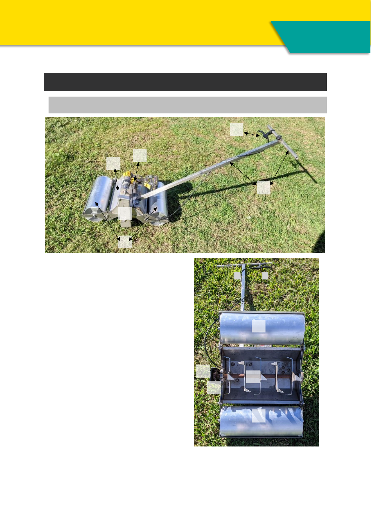
The Ellia 3000......................................................................................... 4
Overview.............................................................................................................................................4
Safety Instructions .................................................................................. 5
Contents of box ...................................................................................... 7
Assembly Instructions .............................................................................. 8
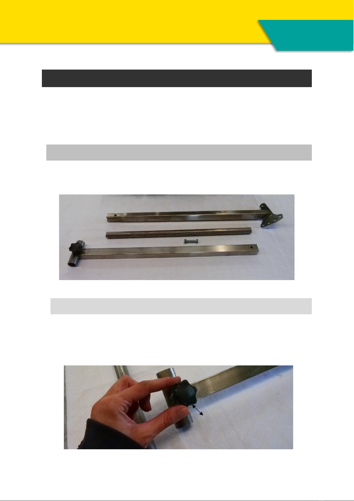
Handle Assembly.................................................................................................................................8
Step 1. .............................................................................................................................................8
Step 2. .............................................................................................................................................9
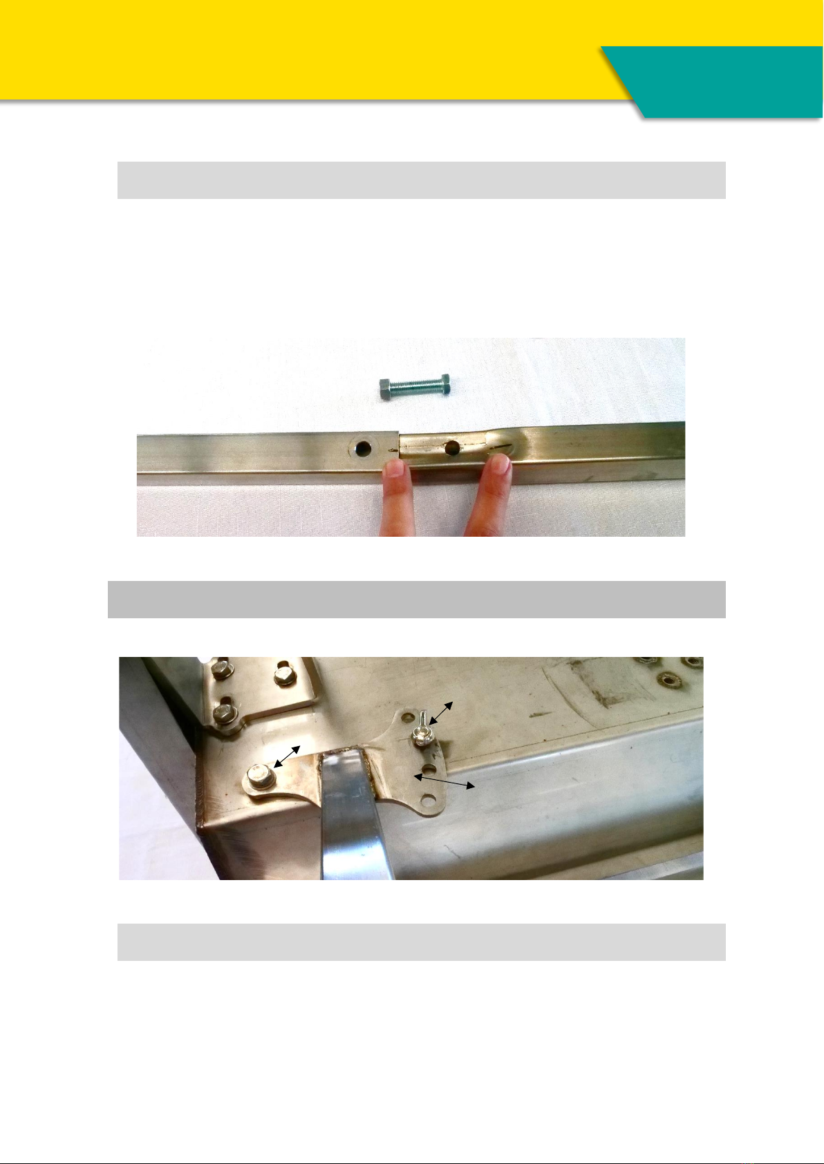
Handle to Main Body Assembly..........................................................................................................9
Step 1. .............................................................................................................................................9
Step 2. ...........................................................................................................................................10
Drill Holder........................................................................................................................................10
Step 1. ...........................................................................................................................................10
Step 2. ...........................................................................................................................................10
Step 3. ...........................................................................................................................................11
Step 4 ............................................................................................................................................11
Step 5. ...........................................................................................................................................12
Roller/Scraper Assembly...................................................................................................................12
Step 1. ...........................................................................................................................................12
Step 2. ...........................................................................................................................................13
Step 3. ...........................................................................................................................................14
Changing Attachments ........................................................................... 14
Step 1. ...........................................................................................................................................14
Step 2 ............................................................................................................................................15
Step 3 ............................................................................................................................................16
Step 4 ............................................................................................................................................16
Operating instructions............................................................................ 17
Maintenance......................................................................................... 17
Warranty ............................................................................................. 17
Contact Us ........................................................................................... 18

Ellia 3000Hand-E | MODEL V2021
P a g e | 2
Thank You
Thank you for purchasing the Ellia 3000!
The Ellia 3000 is a multi-tool with interchangeable attachments that allows you to
fulfil the main tasks of soil preparation in one compact unit powered by a battery
drill.
At Curly’s Ag, we are proud to be the first manufacturers of this type of equipment,
and we are committed to continue improving its design and capabilities for many
years to come.
As a valued customer, your feedback is especially important in this process. So
please, feel free to reach out to us with your comments, suggestions, or questions.
Together we can make small scale farming more profitable and sustainable for the
next generations.
Because of our continuous development and improvements, this manual could
become outdated, so please, check our website for the latest information, or
contact us if you have any questions.
We hope you enjoy your Ellia 3000 and that it helps on getting your farm to the
next level.
Yours sincerely,
Curly’s Ag team

Ellia 3000Hand-E | MODEL V2021
P a g e | 3
This manual
This manual provides practical instructions for the safe use of the Ellia 3000. It
must be read and applied in its entirety to ensure the safe use of the Ellia 3000 in
small scale agricultural settings.
Users of the Ellia 3000 do so at their own risk and acknowledge the use of the
Ellia 3000 involves risks. Users of the Ellia 3000 release and indemnify Curly’s Ag
from any claim, loss, damages, and injury from their use or misuse of the Ellia
3000 including from any reliance on this publication except to the extent such
damage, loss or injury is caused by the negligence of Curly’s Ag.
No part of this publication shall be reproduced, transmitted, or sold in whole or in
any form, without the prior written consent of Curly’s Ag. All trademarks and
registered trademarks appearing in this guide are the property of Curly’s Ag.
© Curly’s Ag – Curly’s Enterprises Pty Ltd, 2022. All Rights Reserved.
WARNING
READ AND UNDERSTAND THIS OPERATOR’S MANUAL COMPLETELY
BEFORE USING YOUR PRODUCT. FAILURE TO FOLLOW OPERATING
INSTRUCTIONS COULD RESULT IN SERIOUS INJURY

Ellia 3000Hand-E | MODEL V2021
P a g e | 4
The Ellia 3000
Overview
A. Handle
B. Throttle/Trigger Squeezer
C. Drill Holder
D. Roller/Scraper
E. Main Body
F. Chain Guard
G. Chain
H. Scratcher Attachment
C
B
B
A
A
E
D
D
D
G
F
F
H

Ellia 3000Hand-E | MODEL V2021
P a g e | 5
Safety Instructions
It is the legal duty of the purchaser of the Ellia 3000 to ensure the user is properly
trained and supervised to use the Ellia 3000 safely without risk to themselves or
others. Operator Safety is our priority, this manual demonstrates some of the
obvious risks, however there might be more risks depending on the environment
and conditions where the Ellia 3000 is being used. Be cautious and always apply
good judgement. It is the operator’s responsibility to be aware and alert for any
equipment or environmental conditions that could compromise the safe operation
of the Ellia 3000.
1. Read all safety instructions before using the Ellia 3000. All operators, no
matter how much experience they may have, should read this and other
related manuals before operating the Ellia 3000 or any attachments related
to the Ellia 3000. It is the owner’s obligation to instruct all operators in
the safe operation of the Ellia 3000.
2. We recommend that you wear protective safety items: Safety Boots, Long
pants, eye, hearing, and hand protection. We highly recommend that no
loose clothing be worn when operating the Ellia 3000.
3. Do not operate the Ellia 3000 if you have not read or do not understand its
manual.
4. Do not operate any equipment if you are subject to seizures, loss of
consciousness or fainting.
DANGER
MOVING PARTS! NEVER REACH INTO MOVING PARTS WHILE IN
USE.
ALWAYS DISCONNECT DRILL BEFORE MANIPULATING PARTS
WITH HANDS.

Ellia 3000Hand-E | MODEL V2021
P a g e | 6
5. Do not use the Ellia 3000 if you are under the influence of alcohol, drugs
(including prescription medications), controlled substances or are fatigued.
6. Do not allow children (under the age of 16) to operate the Ellia 3000 at
any time.
7. Always carefully check the vicinity of the Ellia 3000 before operating it or
any implements attached to it. Do not allow any bystander(s) (including
animals) around or near the Ellia 3000 when in operation.
8. Do not place any parts of your body near any moving parts while in use.
9. Always disconnect the drill before putting any body parts near moving
parts.
10. Always disconnect the drill when finished using.
11. Do not modify the Ellia 3000 or its attachments, modifications may affect
the performance and function of the machine. This may result in injury and
will void warranty.
12. Only use attachments that are designed for use with this machine as listed
under Attachments.
13. The Ellia 3000 requires a skilled operator to be strong enough to guide the
machine while moving, otherwise it could pull you and injury may occur.

Ellia 3000Hand-E | MODEL V2021
P a g e | 7
Contents of box
*Please note that the tools (as per red box) are not included in the contents of this box and do not come as
part of the product.
A. Handle F. Chain Guard
B. Throttle/Trigger Squeezer G. Chain
C. Drill Holder H. Scratcher Attachment
D. Roller/Scraper I. Mulcher Attachment
E. Main Body J. Bed Former Attachment
K. Sprocket/Drill shaft
Assorted Nuts and Bolts (these will be in pre-installed positions for assembly)
Depending on what you purchased will depend on what attachments you will receive in
your kit.
A
H
G
F
E
D
C
B
I
J
*
K

Ellia 3000Hand-E | MODEL V2021
P a g e | 8
Assembly Instructions
You will need some tools –A Cordless Drill to use with the machine, 13mm (1/2”)
and 17mm (11/16”) Spanner or Socket, Phillips head screwdriver, and Allen keys
(a small rubber tipped hammer may also be need).
Handle Assembly
The handle comes in 3 Pieces - 1. Handrail, 2. Upper arm, 3. Lower arm.
(See figure a)
Figure a
Step 1.
Take the Handrail (1) and slide it through the Upper arm (2) (you might need to
undo the knob) Tighten the knob once you are happy with where the Handrail is
sitting. (This needs to be pretty tight to avoid movement while operating the Ellia
3000)
1
3
2
2
1
knob

Ellia 3000Hand-E | MODEL V2021
P a g e | 9
Step 2.
Take the upper arm (2) and attach it to the Lower Arm (3), make sure you take
out the nut and bolt first. Slide together so that the pre-drilled bolt holes align,
(note that there is a small black mark to help align the holes –it is a tight tolerance
fit so you may need to gently tap it together with a rubber tipped hammer) Once
you have them aligned, you can slide the bolt all the way through and do up the
nut tightly (13mm nut)
Handle to Main Body Assembly
Step 1.
Take the Main Body (E) and undo the bolts, washer, and wing nut. Then take your
fully assembled handle and slide onto the Main body (E).
3
2
E
Wing nut
Adjuster Mount
Mount hole

Ellia 3000Hand-E | MODEL V2021
P a g e | 10
Step 2.
Insert the bolt and washer into the mount hole and into the Main Body (E) and
tighten. Insert the wing nut, nut (spacer) and washer into the adjusting mount
and into the Main Body (E) and tighten. 4 holes to choose from, however we
recommend starting with the second hole from the top –this gives you a straight
handle, the handle can be adjusted here at any time.
Drill Holder
Step 1.
Undo the 3 nuts/bolts from the Main Body (E), take the Drill Holder (C) and attach
the end with the adjuster to the 3 bolts on the Main Body. Do up the bolts finger
tight so that the Drill Holder can slide for adjustment.
Step 2.
Take the drill that you will be using, (make sure you have taken the battery
pack off for this stage of the assembly). Take your drill and insert the chuck
onto the shaft (K) and tighten the drill chuck.
C
Adjuster End
Drill Shaft
C
K

Ellia 3000Hand-E | MODEL V2021
P a g e | 11
Step 3.
Loosen the wing nut on the Drill Holder (C). Slide the holder along the Main Body
until the Drill slips into the Holder.
Step 4
Pull the cable through so the Trigger rests onto the Drill Trigger (see figure b),
(make sure that the other end of the cable is firmly pushed into the actual Throttle)
(see figure c). Once you have the trigger set, bend the cable over and do up the
wing nut tight (this holds the cable into place) (see figure d). Do up the bolts for
the Adjuster so the Holder can’t move (see figure e).
Figure b Figure c
Wing Nut
C

Ellia 3000Hand-E | MODEL V2021
P a g e | 12
Figure d Figure e
Step 5.
Take the cable and wrap it around the Handle stem twice (A), if you are right
handed push the throttle (B) onto the right side of the handle, and if you are left
handed push throttle onto the left hand side of the handle. Do up the throttle using
an allen key so its nice and tight.
Test the throttle, by pulling in the Throttle (B) and it should pull in the drill trigger
sufficiently. (Do not put the battery back in to test this, it’s a visual test only).
Roller/Scraper Assembly
Step 1.
Take one of the Rollers (D) and remove the Wing nuts and bolts that are already
in place (see figure f). On the Main Body, remove the Chain Guard (F) by undoing
the top nut and the wing nut at the bottom. (See figure g). (Once you have
experience with this, you can just partially undo the top nut to gain access instead
of removing it completely. This will allow for quicker changing of the implements.)
B
A

Ellia 3000Hand-E | MODEL V2021
P a g e | 13
Figure f Figure g
Step 2.
Once you have uncovered the Chain (G), it will give you access to the rear holding
nut (hidden behind the lower sprocket). Hook the hook end of the roller (D) onto
the rear holding nut. Each side has one. Lift the roller up so that the adjuster holes
line up with the Main Body (E), take the bolt and insert this from the inside out
so that the wing nut is accessible from the outside, do this on both sides and do
up the wing nuts. This can be adjusted as you go depending on the height you
require. Repeat for the other roller.
TIP: Count the holes from top down so you have it even on both sides.
Nut
Wing
nut
Wing nut and bolt
Holding nut
Bolt and Wing nut
D
F
G
E
D

Ellia 3000Hand-E | MODEL V2021
P a g e | 14
Step 3.
Put the Chain Guard (F) back into place and do up the bolt and wing nut. Test
that the Ellia 3000 moves smoothly by running it back and forth on a level surface.
It should move smoothly. If it seems to not roll smoothly, check that the rollers
are level by checking the adjuster bolts (count the holes that the bolts are in to
make sure they are the same).
Changing Attachments
ALWAYS DISCONNECT DRILL OR MAKE SURE BATTERY IS OUT BEFORE
MANIPULATING PARTS WITH HANDS.
BEWARE THAT SOME OF THE ATTACHMENTS ARE SHARP
(We recommend wearing protective gloves)
Step 1.
Take off the Chain Guard (F). Turn the main body upside down. Near the sprocket,
there is a small latch covering the bearing holder (See figure h). Pull this latch
outwards it will release the holder.
BED FORMER
SCRATCHER
MULCHER

Ellia 3000Hand-E | MODEL V2021
P a g e | 15
Figure h
Step 2
Push the whole attachment outward (towards the sprocket end) –Caution some
of the attachments are sharp use safety gloves for protection. (See figure i).
Figure i
Latch, pull out

Ellia 3000Hand-E | MODEL V2021
P a g e | 16
Step 3
Chain should now be loose. Unhook chain from top sprocket and take the
attachment out from Main body.
Step 4
Take the attachment you want to change, place the attachment in the main body,
with the sprocket end in line with the small sprocket, hook the chain back into
place (this may take some jiggling as the tolerance for the chain should be
reasonably tight). Pull the latch back a bit to make sure it’s not covering holder so
that the sprocket bearing can easily slide into place.
Push the other end of the attachment into place so that the bearing is sitting in
the bearing holder. Make sure the sprockets are aligned straight. Push the latch
back into place, this will also hold the bearing so if it doesn’t close back over the
bearing something is misaligned. (See figure j)
Figure j
Flip the Ellia 3000 back over and re install the chain guard (F) into place making
sure they are tight.
Now you can re attach the drill or the battery and you are ready to use.
Bearing
Holder
Latch

Ellia 3000Hand-E | MODEL V2021
P a g e | 17
Operating instructions
Place the Ellia 3000 where you wish to start using it. Once you have installed the
drill making sure the chuck is tight, pull the trigger handle and the machine will
start to move forward.
Always make sure the chain guard is in place before operation to avoid things
getting stuck in the chain.
Reminder: you can change the Handle position and the Roller heights as required
when on the fly.
Maintenance
As the Ellia 3000 is made from Stainless steel it can be left out in the elements,
however we do recommend that you disconnect the drill and take the drill out of
the elements.
You may need to lube the chain every now and then depending on how long it has
been left outside or how much dirt and mud it accumulates.
If you have a lot of organic material in your soil, you may find that it wraps around
the shaft, check for this before each use (sometimes even during the use of the
Ellia 3000). Make sure you have the drill either disconnected or battery take out
before you do this.
Bearings may also accumulate dirt if left sitting in the elements, so a quick light
tap with a rubber mallet to dislodge any dirt in the bearings before use may be
required.
Warranty
The Ellia 3000 is warranted under the Curly’s Ag limited warranty of 12 months.
No warranty shall, however, apply if the Ellia 3000 has not been used according
to the instruction given in this manual, even if it is within the warranty period.

Ellia 3000Hand-E | MODEL V2021
P a g e | 18
Contact Us
We value your opinion, please feel free to contact us if you have questions or
comments.
Website www.curlysag.com
Phone Office Phone +61 493 281 690
Curly's Phone +61 449 268 131
Video Ellia 3000 Assembly Video
Ellia 3000 Changing Attachment Video
Table of contents
Other CURLY'S AG Farm Equipment manuals