manuals.online logo
Brands
  1. Home
  2. •
  3. Brands
  4. •
  5. curt
  6. •
  7. Automobile Accessories
  8. •
  9. curt CM-58967 User manual

curt CM-58967 User manual

Other curt Automobile Accessories manuals

curt 16028 User manual

curt

curt 16028 User manual

curt 57009 User manual

curt

curt 57009 User manual

curt CM 18031 User manual

curt

curt CM 18031 User manual

curt 45832 User manual

curt

curt 45832 User manual

curt 18410 User manual

curt

curt 18410 User manual

curt 12142 User manual

curt

curt 12142 User manual

curt 11454 User manual

curt

curt 11454 User manual

curt R16 5TH User manual

curt

curt R16 5TH User manual

curt 11354 User manual

curt

curt 11354 User manual

curt 13490 User manual

curt

curt 13490 User manual

curt SWAY CONTROL User manual

curt

curt SWAY CONTROL User manual

curt 58909 User manual

curt

curt 58909 User manual

curt 45952 User manual

curt

curt 45952 User manual

curt 55513 User manual

curt

curt 55513 User manual

curt 13532 User manual

curt

curt 13532 User manual

curt 70141 User manual

curt

curt 70141 User manual

curt 70130 User manual

curt

curt 70130 User manual

curt 70118 User manual

curt

curt 70118 User manual

curt 16055 User manual

curt

curt 16055 User manual

curt 13119 User manual

curt

curt 13119 User manual

curt 11232 User manual

curt

curt 11232 User manual

curt 16315 User manual

curt

curt 16315 User manual

curt 18112 User manual

curt

curt 18112 User manual

curt 13454 User manual

curt

curt 13454 User manual

Popular Automobile Accessories manuals by other brands

Magneti Marelli AC161 Installation instruction

Magneti Marelli

Magneti Marelli AC161 Installation instruction

FDI uEZ GUI Start here

FDI

FDI uEZ GUI Start here

JCROffroad JT Install instructions

JCROffroad

JCROffroad JT Install instructions

Rostra VOXXElectronics 250-1930 owner's guide

Rostra

Rostra VOXXElectronics 250-1930 owner's guide

TOP VEHICLE TECH GR3FORD5 installation manual

TOP VEHICLE TECH

TOP VEHICLE TECH GR3FORD5 installation manual

Safe Fleet PRIME DESIGN AR-2000-BLK manual

Safe Fleet

Safe Fleet PRIME DESIGN AR-2000-BLK manual

Skoda Fabia Combi 5J Fitting instructions

Skoda

Skoda Fabia Combi 5J Fitting instructions

Camcar 40077 Al Mounting instructions

Camcar

Camcar 40077 Al Mounting instructions

Camcar 40089 AL Mounting instructions

Camcar

Camcar 40089 AL Mounting instructions

Impac Tradesman 2000 installation manual

Impac

Impac Tradesman 2000 installation manual

DVB OFFROAD BRSB-01 installation manual

DVB

DVB OFFROAD BRSB-01 installation manual

Safari Snorkel SS385HF installation guide

Safari Snorkel

Safari Snorkel SS385HF installation guide

ULTIMATE SPEED 279746 Assembly and Safety Advice

ULTIMATE SPEED

ULTIMATE SPEED 279746 Assembly and Safety Advice

SSV Works DF-F65 manual

SSV Works

SSV Works DF-F65 manual

ULTIMATE SPEED CARBON Assembly and Safety Advice

ULTIMATE SPEED

ULTIMATE SPEED CARBON Assembly and Safety Advice

Witter F174 Fitting instructions

Witter

Witter F174 Fitting instructions

WeatherTech No-Drill installation instructions

WeatherTech

WeatherTech No-Drill installation instructions

TAUBENREUTHER 1-336050 Installation instruction

TAUBENREUTHER

TAUBENREUTHER 1-336050 Installation instruction

manuals.online logo
manuals.online logoBrands
  • About & Mission
  • Contact us
  • Privacy Policy
  • Terms and Conditions

Copyright 2025 Manuals.Online. All Rights Reserved.

58967-INS-RB •PAGE 1
Wiring Location Guide*
for Trucks (T)
T1 Behind driver side taillight housing
T2 Behind passenger side taillight housing
T3 Behind driver side rear bumper
T4 Behind center of rear bumper fascia
T5 Behind passenger side rear bumper
T2
T4 T5
T1
T3
* Representative vehicle shown
INSTALLATION MANUAL
Tools Required
Drill Flathead screwdriver
Drill bit, 3/32" Cutting tool
Wiring Location(s)
T3 and T5
Level of Difficulty
Easy
WARNING
Do not exceed product rating or tow vehicle lamp load rating, whichever is lower.
Product Registration and Warranty
CURT Group stands behind our products with industry-leading warranties.
Provide feedback and help us to improve our products by registering your purchase at:
warranty.curtgroup.com/surveys
Maintenance
Periodic inspection of all wires and connections should be performed
to ensure there is no visible damage or loose connections.
NOTICE
Before you begin installation, read all instructions thoroughly.
Proper tools will improve the quality of installation and reduce the time required.
All steps must be followed to ensure the product will function properly. Once installed,
test for proper function by using a test light or connecting a properly wired trailer.
Product Photo
Included Parts
58967-INS-RB •PAGE 2
Step 1
Locate the vehicle battery. Look up the
battery location in the owner's manual of
your vehicle. Disconnect the negative battery
terminal. Be sure to fasten this wire down
and away from the battery when completing
the installation process.
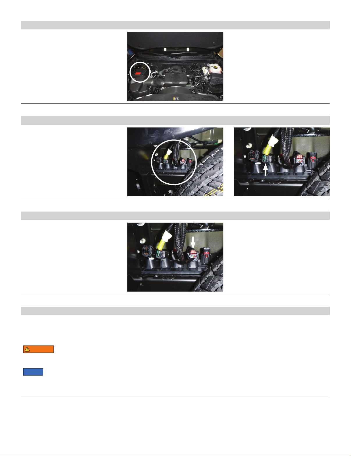
Step 2
Locate the electrical junction box at the
rear of the vehicle between the frame rail
and the spare tire on the driver side. Locate
the driver-side taillight harness. You may
need to trace the wires back to the taillight.
Separate the connectors, taking care not
to damage the locking tabs. Install the
custom RV harness with the yellow wire
in-between the factory harness.
Step 3
In the same junction block is the passenger-
side harness. You may need to trace the wires
back to the taillight. Separate the connectors,
taking care not to damage the locking tabs.
Install the custom RV harness with the green
wire in-between the factory harness.
Step 4
Locate a grounding point near the box such as an existing screw or bolt in the frame
of the vehicle or drill a 3/32” pilot hole. The area should be free from rust, dirt, and
paint (Use abrasive pad/paper to remove rust and paint). Secure the white ground
wire with the ring terminal on the existing fastener or with the provided ground screw.
WARNING
Check for miscellaneous items that may be hidden behind or under
any surface before drilling to avoid damage and / or personal injury.
NOTICE
Once the custom wiring harness is installed, verify that the harness is functioning
by attaching the 4-flat to any vehicle with functioning trailer lights. The taillights
on the tow vehicle should function along with the taillights on the towing vehicle.
58967-INS-RB •PAGE 3
Step 5
Route the 4-flat harness above the junction
block between the frame and the bed of
the truck. Continue along the driver-side
frame rail to the front of the truck.
Step 8
From the engine compartment ext to the hood
hinge on the driver side, pull back the rubber
filler and run a fish wire down between the
inner fender and the outer fender. Pull the
wheel well panel back and locate the end
of the fish wire. Attach to the 4-flat and
pull to the top of the engine compartment.
Step 6
Route the 4-flat above and along the frame
rail to just behind the driver-side front wheel.
Use the provided cable ties to loosely secure
the wire along the frame rail as needed.
Step 7
Once the harness is just behind the driver-side
front wheel, route the 4-flat harness to
the rear of the driver-side wheel well.
58967-INS-RB •PAGE 4
Step 9 - How to use fish wire
A) Fish wire is a way to push or pull
an electrical wire through a blind hole.
Make sure the wire is long enough
to stick out on the other side.
Insert the fish wire through the blind
hole and locate it on the other side.
B) Use tape to secure the harness
to the fish wire and pull back up.
The fish wire or harness may get hung up on
something, if this happens you may have to
push back down, wiggle it around or twist the
wire to loosen it from what it’s hung up on.
Fish wire could be anything from a cut-up wire
hanger, stiff wire, rope or string depending on
what is needed for the installation.
Step 10
Route the 4-flat under the outer fender
mounts and around the washer fluid tank.
Mount the 4-flat to the driver-side front
core support and zip tie as needed.
Step 11
Secure any excess wire so that it is not drooping or dangling, but not so tight that
it causes unnecessary strain to the wire which could lead to breakage over time.
After removing slack from the 4-flat wire, tighten any zip ties and add as needed.
Use a zip tie to fasten any excess wire to a solid spot along the driver-side inner fender.
Reinstall all items removed during install. If it was disconnected at the beginning of the installation,
reconnect the negative battery terminal. Install the provided 4-flat dust cover to help prevent corrosion.
A
B
A
B