56093-INS-RC •01/14/2021 •ECN7905 •PAGE 7 OF 7
POWERED CONVERTER LEAD INSTRUCTION SHEET
FICHE DE CONSIGNES DU CONVERTISSEUR D'ALIMENTATION
HOJA DE INSTRUCCIONES DEL CONDUCTOR DEL ADAPTADOR ALIMENTADO POR BATERÍA
Illustrations are for reference only. Battery
location may differ depending on the vehicle.
Les images ne sont fournies qu'à des fins de
référence. L'emplacement de la batterie peut
varier en fonction du véhicule.
Las ilustraciones son solo para
referencia. La ubicación de la batería
puede variar según el vehículo.
1. This converter system is to be used only on 12 volt negative ground systems.
2. Secure power wire to vehicle chassis using cable ties provided.
3. When passing the power wire through sheet metal, use an existing grommet,
add a grommet or use silicone to protect the power wire from sharp edges.
4. Overall T-connector design may differ from illustration. The illustration
should be used for power lead instruction only. Illustration is not to scale.
1. Ce système de convertisseur ne doit être utilisé
qu'avec une prise de masse de polarité négative de 12volts.
2. Fixer le câble d'alimentation au châssis du véhicule
à l'aide des courroies d'attache de câble fournies.
3. Utiliser un œillet existant, ajouter un œillet ou appliquer du silicone pour protéger le
câble d'alimentation des rebords tranchants au moment de le passer à travers la tôle.
4. La disposition générale du connecteur en T peut différer de l'illustration. Celle-ci ne doit
être utilisée que pour le convertisseur d'alimentation. L'illustration n'est pas à l'échelle.
1. Este sistema de adaptadores solo se debe utilizar
con sistemas con polo negativo a masa de 12voltios.
2. Sujete el cable de alimentación al chasis del
vehículo utilizando los sujetacables suministrados.
3. Al pasar el cable de alimentación por la lámina de metal, utilice la
arandela pasacable existente, agregue una arandela pasacable o utilice
silicona para proteger el cable de alimentación de los bordes filosos.
4. El diseño general del conector T puede ser distinto de la ilustración. La ilustración solo se
debe utilizar para la instrucción del conductor de alimentación. La ilustración no está a escala.
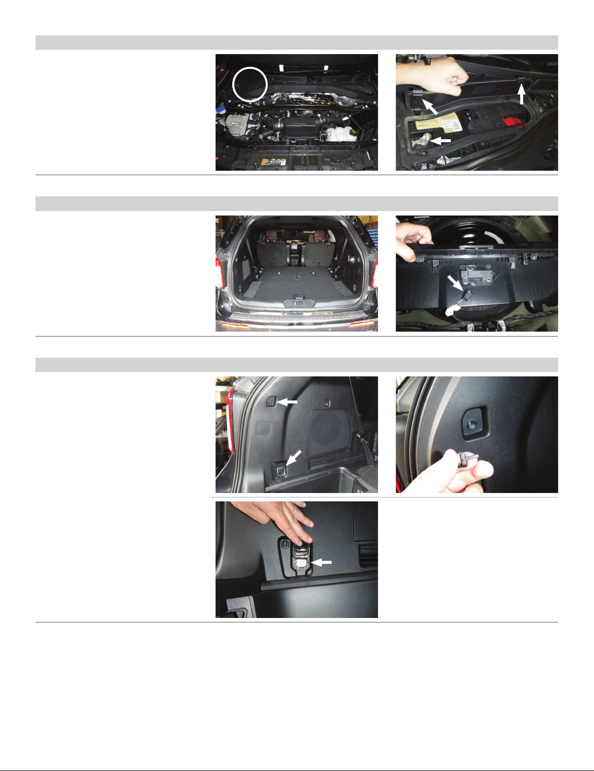
Route 12 GA wire to vehicle battery location,
taking care to avoid any pinch points and hot
or rotating components.
Acheminer le câble de calibre12 à la batterie du
véhicule en prenant soin d'éviter les points de
pincement et les éléments chauds ou pivotants.
Pase el cable calibre 12 hacia la ubicación de
la batería del vehículo, con cuidado de evitar
atascos y componentes calientes o giratorios.
To avoid personal injury or property damage, check for miscellaneous
items that may be behind or under any surface before drilling.
Pour éviter les blessures et les dommages matériels, vérifier les divers
articles qui peuvent se trouver derrière ou sous la surface avant de percer.
Para evitar lesiones personales o daños materiales, verifique que no haya
ningún elemento detrás o debajo de la superficie antes de perforar.
WARNING
AVERTISSEMENT / ADVERTENCIA
WARNING
AVERTISSEMENT / ADVERTENCIA
NOTICE
AVIS / AVISO
NOTICE
AVIS / AVISO
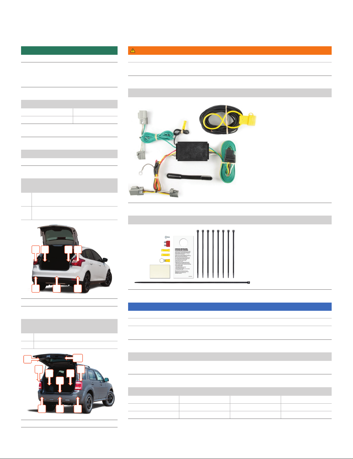
Use ring terminal
for battery connection
Utiliser une cosse à
anneau pour effectuer la
connexion à la batterie
Utilizar el terminal de
anillo para la conexión
de la batería
If using the converter as a powered
module for a two-wire system, the
red brake wire must be grounded
Si le convertisseur est utilisé comme
module d'alimentation pour un système
à deux fils, le câble de freinage rouge
doit être mis à la masse
Si se utiliza el adaptador como un módulo
energizado para un sistema bifilar, el cable
rojo del freno debe estar conectado a tierra
Fuse holder with 10 amp
fuse max (install fuse after
all other steps are complete)
Porte-fusible avec fusible de 10A
max (installer le fusible après avoir
effectué toutes les autres étapes)
Portafusible con fusible de
10A máx. (instalar fusible una
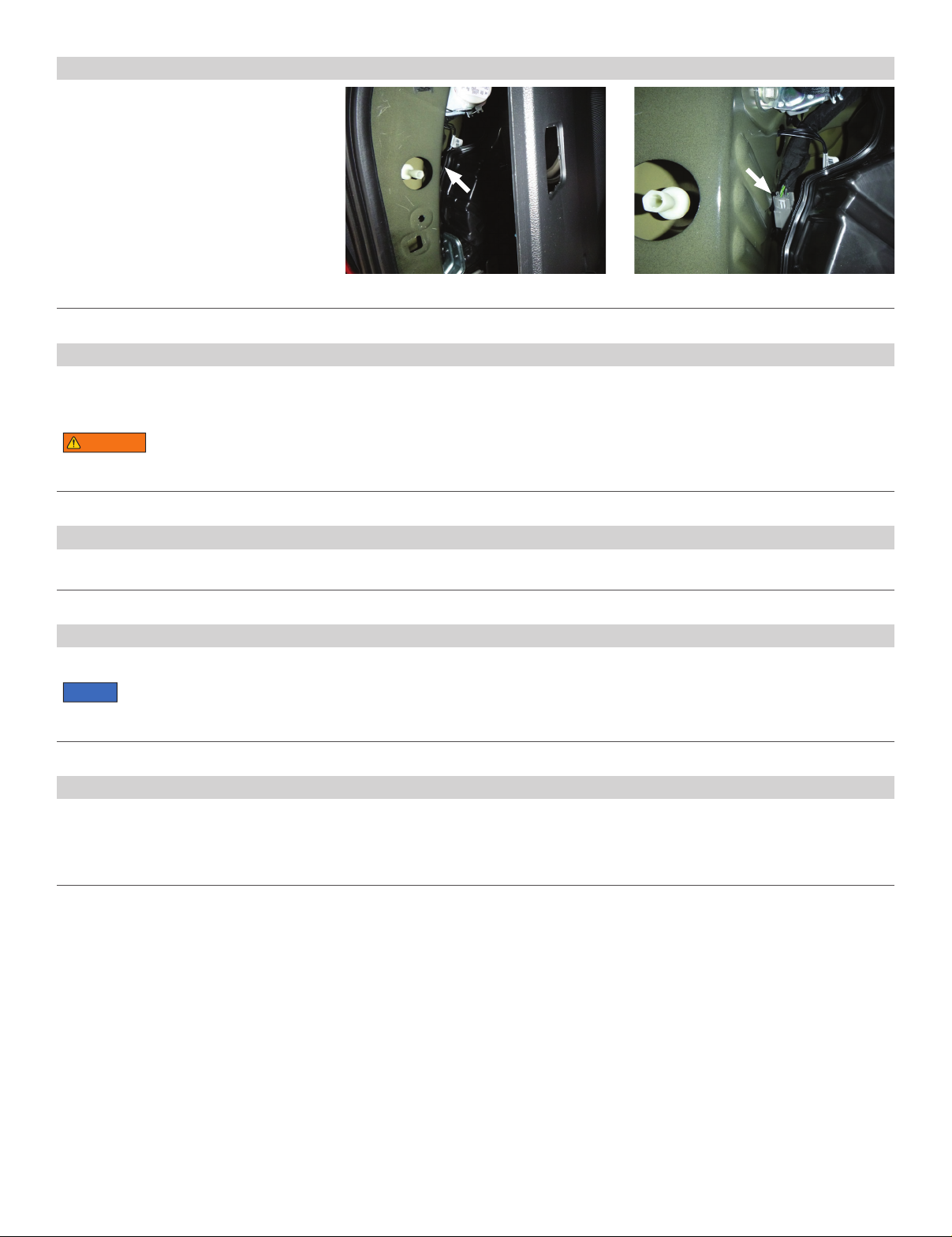
vez completados los otros pasos) Attach the ring terminal of the white ground
wire to vehicle body using the screw provided
(drill 3/32"hole if necessary)
Attacher la cosse à anneau du fil de terre blanc
à la carrosserie du véhicule à l'aide de la vis
fournie (percer un trou de 3/32po au besoin)
Conectar el terminal de anillo del cable a tierra
blanco a la carcasa del vehículo utilizando el
tornillo suministrado (haga una perforación
de 3/32" si es necesario)
Mount converter using the
provided double-sided tape
Installer le convertisseur à l'aide
du ruban adhésif double face fourni
Montar el adaptador utilizando la
cinta de doble cara suministrada
Vehicle battery
Batterie du véhicule
Batería del vehículo
Generic housings shown for reference only
Les boîtiers génériques ne sont fournis qu'à des fins de référence
Se muestran carcasas genéricas, solo para referencia
Butt connector
Raccord bout à bout
Conector a tope
Butt connector
Raccord bout à bout
Conector a tope
Converter
Convertisseur
Adaptador
12 GA wire or larger
Câble de calibre12 ou plus
Cable calibre 12 o mayor
Disconnect negative battery (-)
cable before wiring the power wire
Déconnecter le câble négatif (-) de la batterie
avant d'installer le câble d’alimentation
Desconectar el cable negativo (-) de la batería
antes de conectar el cable de alimentación
Route black wire to
positive battery (+)
Connecter le câble noir à la
borne positive (+) de la batterie
Pasar el cable negro hacia
el polo positivo (+) de la batería
12-1012-10
Green - Right turn
Red - Brake
Yellow - Left turn
Brown - Taillight
Vert - Clignotant droit
Rouge - Frein
Jaune - Clignotant gauche
Brun - Feu arrièr
Verde - Giro a la derecha
Rojo - Freno
Amarillo - Giro a la izquierda
Marrón - Luces traseras