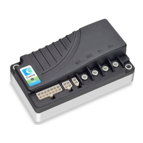
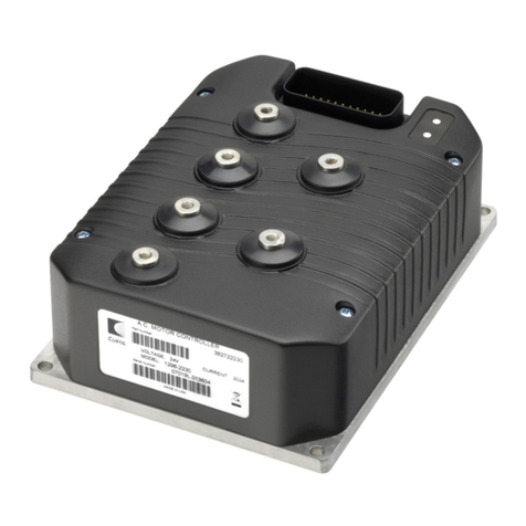
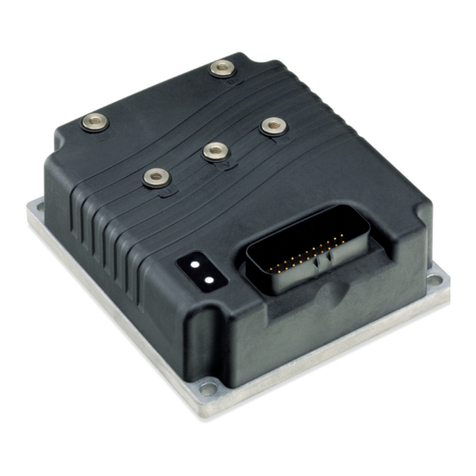
Curtis 1226 User manual

Read Instructions Carefully!
Specications are subject to change without notice.
© 2019 Curtis Instruments, Inc. ® Curtis is a registered trademark of Curtis Instruments, Inc.
© The design and appearance of the products depicted herein are the copyright of Curtis Instruments, Inc. 53229, RevA 9/19
Curtis Instruments, Inc.
200 Kisco Avenue
Mt. Kisco, NY 10549
www.curtisinstruments.com
Manual
Model 1226
Brushed Permanent Magnet Controller

Curtis Model 1226 – September 2019
pg. ii
CHAPTERS
1: OVERVIEW ...................................................................................................................................... 1
Easy Installation and Set-up ................................................................................................... 2
Smooth and Secure Control.................................................................................................... 2
Highly Flexible I/O .................................................................................................................. 2
Valuable Additional Features................................................................................................... 3
Meets or Complies with Relevant US and International Regulations ........................................ 3
GETTING THE MOST OUT OF YOUR CONTROLLER.......................................................................... 3
2: INSTALLATION AND WIRING ............................................................................................................ 4
MOUNTING THE CONTROLLER ...................................................................................................... 4
HIGH CURRENT CONNECTIONS .................................................................................................... 5
LOW CURRENT CONNECTIONS ..................................................................................................... 6
Motor Connector (J1) ............................................................................................................. 6
Communication Port (J2) ....................................................................................................... 7
Logic Connector (J3) ............................................................................................................. 7
Pin Protection ........................................................................................................................ 9
I/O Ground Specications ...................................................................................................... 9
WIRING DIAGRAM: STANDARD CONFIGURATION........................................................................... 10
INPUTS AND OUTPUTS (I/Os) ....................................................................................................... 11
Analog Inputs ....................................................................................................................... 11
Switch Inputs ........................................................................................................................ 12
Switches with Integrated LED Drivers.................................................................................... 13
Driver Outputs....................................................................................................................... 14
Throttle Pot ........................................................................................................................... 15
Speed Limit Pot..................................................................................................................... 17
Keyswitch ............................................................................................................................. 17
Emergency Stop Switch......................................................................................................... 18
Interlock Input ....................................................................................................................... 18
Push Switch .......................................................................................................................... 18
Emergency Reverse Input...................................................................................................... 19
Belly Button Check................................................................................................................ 20
TABLE OF CONTENTS

Curtis Model 1226 – September 2019 pg. iii
TABLE OF CONTENTS cont’d
Electromagnetic Braking ....................................................................................................... 21
Mode Switch ......................................................................................................................... 21
Battery Discharge Indicator (BDI)........................................................................................... 22
Charger Inhibit ...................................................................................................................... 22
Circuitry Protection Devices................................................................................................... 22
External Status LED............................................................................................................... 23
Horn...................................................................................................................................... 23
External Power Supply........................................................................................................... 24
Load Hold Contactor.............................................................................................................. 24
Hydraulic Pump Contactor..................................................................................................... 24
Reverse Switch ..................................................................................................................... 25
Speed Sensor........................................................................................................................ 25
Motor Temperature Sensor .................................................................................................... 26
3: PROGRAMMABLE PARAMETERS .................................................................................................... 27
APPLICATION SETUP MENU.......................................................................................................... 27
Speed Mode Menu ................................................................................................................ 27
Mode 1 and Mode 2 Menus................................................................................................... 28
Other Menu........................................................................................................................... 29
Fine Tuning Menu.................................................................................................................. 30
Understanding Low and High Speed Acceleration Rates ........................................................ 31
Understanding Low and High Speed Brake Deceleration Rates .............................................. 32
Throttle Menu........................................................................................................................ 33
Understanding the Throttle Response Parameters.................................................................. 35
Understanding the HPD/SRO Function ................................................................................... 36
Interlock Braking Menu ......................................................................................................... 36
Main Relay Menu .................................................................................................................. 37
EM Brake Menu..................................................................................................................... 38
Understanding Electromagnetic Braking ................................................................................ 38
Battery Menu ........................................................................................................................ 39
Overvoltage and Undervoltage Protection .............................................................................. 39

Curtis Model 1226 – September 2019
pg. iv
TABLE OF CONTENTS cont’d
Undervoltage Controller Menu ............................................................................................... 40
Overvoltage Controller Menu ................................................................................................. 40
BDI Setup Menu .................................................................................................................... 41
Emergency Reverse Menu..................................................................................................... 42
Horn Menu ............................................................................................................................ 44
Drivers Menu ........................................................................................................................ 44
Hydraulic Contactor Driver Menu ........................................................................................... 44
Load Hold Contactor Driver Menu .......................................................................................... 45
Aux 1 and Aux 2 Contactor Driver Menus............................................................................... 45
MISC Menu ........................................................................................................................... 46
Controller Setup Menu........................................................................................................... 47
Analog Inputs Menu .............................................................................................................. 47
IO Assignment Menu ............................................................................................................. 49
Outputs Menu ....................................................................................................................... 51
Current Limits Menu.............................................................................................................. 51
Motor Setup Menu................................................................................................................. 52
Motor Menu .......................................................................................................................... 52
Compensation Menu ............................................................................................................. 53
Speed Sensor Menu .............................................................................................................. 53
Motor Temperature Control Menu .......................................................................................... 54
4: MONITOR MENU ............................................................................................................................ 56
CONTROLLER MENU.................................................................................................................... 56
BATTERY MENU ........................................................................................................................... 58
OUTPUTS MENU .......................................................................................................................... 58
MOTOR MENU ............................................................................................................................. 59
INPUTS MENU.............................................................................................................................. 60
Switches Menu ..................................................................................................................... 60
Analog Inputs Menu .............................................................................................................. 61
Control Inputs Menu.............................................................................................................. 61
5: INITIAL SETUP ............................................................................................................................... 62
Congure the Wiper Voltage .................................................................................................. 63
Conrm Throttle Operation .................................................................................................... 64
TABLE OF CONTENTS cont’d
6: TUNING VEHICLE PERFORMANCE ................................................................................................... 66
7: CALIBRATING THE BATTERY DISCHARGE INDICATOR (BDI) OUTPUT ................................................ 71
8: DIAGNOSTIC AND TROUBLESHOOTING........................................................................................... 74
PROGRAMMING DEVICE DIAGNOSTICS......................................................................................... 74
LED DIAGNOSTICS....................................................................................................................... 75
Fault Codes ........................................................................................................................... 75
External Status LED............................................................................................................... 76
Troubleshooting Faults .......................................................................................................... 76
9: MAINTENANCE .............................................................................................................................. 85
DIAGNOSTIC HISTORY.................................................................................................................. 85
APPENDIX A: VEHICLE DESIGN CONSIDERATIONS REGARDING
ELECTROMAGNETIC COMPATIBILITY (EMC)................................................................................... 86
EMISSIONS.................................................................................................................................. 86
IMMUNITY ................................................................................................................................... 86
APPENDIX B: EN 13849 COMPLIANCE, CURTIS 1226 CONTROLLER.................................................... 88
APPENDIX C: CURTIS PROGRAMMING DEVICES.................................................................................. 90
PC PROGRAMMING STATION (1314)............................................................................................. 90
HANDHELD PROGRAMMER (1313) ............................................................................................... 90
PROGRAMMER FUNCTIONS ......................................................................................................... 90
APPENDIX D: SPECIFICATIONS ........................................................................................................... 91
Curtis Model 1226 – September 2019 pg. v

Curtis Model 1226 – September 2019
pg. vi
TABLE OF CONTENTS cont’d
FIGURES
FIGURE 1: CURTIS 1226 CONTROLLER................................................................................................ 1
FIGURE 2: MOUNTING DIMENSIONS, CURTIS 1226 CONTROLLER ....................................................... 4
FIGURE 3: MOTOR CONNECTOR PINS (J1) .......................................................................................... 6
FIGURE 4: COMMUNICATION CONNECTOR PINS (J2) .......................................................................... 7
FIGURE 5: LOGIC CONNECTOR PINS (J3) ............................................................................................ 7
FIGURE 6: WIRING DIAGRAM, CURTIS 1226 CONTROLLERS ............................................................... 10
FIGURE 7: WIRING A 2-WIRE THROTTLE POT ...................................................................................... 16
FIGURE 8: WIRING A 3-WIRE THROTTLE POT ..................................................................................... 16
FIGURE 9: BELLY BUTTON WIRING CHECK ......................................................................................... 20
FIGURE 10: LOW SPEED AND HIGH SPEED ACCELERATION RATES ..................................................... 31
FIGURE 11: LOW SPEED AND HIGH SPEED BRAKE DECELERATION RATES ......................................... 32
FIGURE 12: THROTTLE RESPONSE PARAMETERS .............................................................................. 35
FIGURE 13: DIAGNOSTICS MENU FAULTS .......................................................................................... 74
FIGURE 14: FAULT CODE LEDs .......................................................................................................... 75
FIGURE 15: SAFETY CHANNEL BLOCK DIAGRAM, CURTIS 1226 CONTROLLER ................................... 88

pg. vii
TABLES
TABLE 1: HIGH CURRENT TERMINALS ................................................................................................ 5
TABLE 2: LOW CURRENT CONNECTORS ............................................................................................. 6
TABLE 3: J1 CONNECTOR ................................................................................................................... 6
TABLE 4: J2 CONNECTOR .................................................................................................................. 7
TABLE 5: J3 CONNECTOR ................................................................................................................... 8
TABLE 6: PIN PROTECTION SPECIFICATIONS ....................................................................................... 9
TABLE 7: I/O GROUND SPECIFICATIONS............................................................................................... 9
TABLE 8: ANALOG INPUT SPECIFICATIONS ......................................................................................... 11
TABLE 9: SWITCH INPUT ................................................................................................................... 12
TABLE 10: SWITCH INPUT SPECIFICATIONS........................................................................................ 13
TABLE 11: EXTERNAL LED RESISTOR SPECIFICATIONS....................................................................... 13
TABLE 12: DRIVER PWM MODES........................................................................................................ 14
TABLE 13: GENERIC DRIVER SPECIFICATIONS .................................................................................... 15
TABLE 14: THROTTLE POT CONNECTIONS.......................................................................................... 15
TABLE 15: POTENTIOMETER RESISTANCE SPECIFICATIONS ............................................................... 16
TABLE 16: POT WIPER AND POT HIGH ANALOG SPECIFICATIONS ........................................................ 16
TABLE 17: KEYSWITCH INPUT SPECIFICATIONS.................................................................................. 17
TABLE 18: COMPLEMENTARY EMERGENCY REVERSE STATES ............................................................ 19
TABLE 19: BELLY BUTTON CHECK CONFIGURATION............................................................................ 21
TABLE 20: EXTERNAL POWER SUPPLY PINS ....................................................................................... 24
TABLE 21: +5V AND +14V EXTERNAL POWER SUPPLY SPECIFICATIONS............................................. 24
TABLE 22: SINGLE AND DUAL SWITCH THROTTLE CONNECTIONS ...................................................... 25
TABLE 23: SPEED SENSOR SPECIFICATIONS ...................................................................................... 25
TABLE 24: MOTOR TEMPERATURE SENSOR SPECIFICATIONS ............................................................. 26
TABLE 25: THROTTLE TYPES AND DRIVING DIRECTION ...................................................................... 34
TABLE OF CONTENTS cont’d
Curtis Model 1226 – September 2019

pg. viii
TABLE OF CONTENTS cont’d
TABLE 26: HPD AND SRO................................................................................................................... 36
TABLE 27: 1226 CONTROLLER VOLTAGE LIMITS................................................................................. 39
TABLE 28: AUX 1 TYPE AND AUX 2 TYPE PARAMETER VALUES............................................................ 46
TABLE 29: SUPERVISION ERROR FIELD VALUES ................................................................................. 57
TABLE 30: IR COMP AND ANTI-ROLLBACK COMP GUIDELINES .......................................................... 68
TABLE 31: PARAMETERS FOR CONFIGURING BDI .............................................................................. 71
TABLE 32: LED STATUSES ................................................................................................................. 75
TABLE 33: FAULTS ............................................................................................................................ 77
TABLE 34: SAFETY PERFORMANCE ................................................................................................... 89
TABLE 35: MODEL CHART ................................................................................................................. 91
Curtis Model 1226 – September 2019

Return to TOC Curtis Model 1226 – September 2019
1 — OVERVIEW pg. 1
Like all Curtis motor controllers, the 1226 oers superior operator control of the vehicle’s motor
drive speed.
1 — OVERVIEW
e Curtis Model 1226 motor speed controller provides ecient, optimal control of permanent
magnet drive motors for battery powered vehicles. e 1226 controller is optimized for use on light
duty Class III pallet trucks and sweeper scrubber oorcare machines. Highly exible programmability
allows the controller to be used on any low power permanent magnet motor application.
Figure 1
Curtis 1226
Controller

1 — OVERVIEW
Curtis Model 1226 – September 2019 Return to TOC
pg. 2
e following sections describe the 1226 controller’s key features.
Easy Installation and Set-up
• Easily programmed with the Model 1313 handheld programmer or 1314 PC programming
station, or can be supplied pre-programmed.
• Compatible with industrial tiller handle wigwag throttles such as the Curtis Model ET-190E.
• Simplied troubleshooting and diagnostics.
• Industry standard Molex Mini-t Jr. logic connectors and heavier duty M5 threaded
busbars for battery and motor wiring.
Smooth and Secure Control
• Advanced speed regulation maintains precise speed over varied terrain, obstacles, curbs
and ramps.
• Linear cutback of current ensures smooth control with no sudden loss of power during
undervoltage or overtemperature.
• Proprietary algorithms help prevent gearbox wear while providing smooth starts and reversals.
• e vehicle is brought to a complete halt before the electromagnetic brake is applied,
ensuring safe and secure stopping under all conditions.
• Charger inhibit input prevents driving while the charger is connected.
• Emergency Stop Decel function ensures a smooth “brake to stop” when the key is turned
o or a fault that requires the vehicle to stop occurs.
• Emergency reverse with belly button switch input.
• Anti-roll back/roll-forward function provides smooth and safe vehicle control on hills
and ramps.
• Temporary “Boost Current” feature provides greatly improved performance with transient
loads such as starting on a hill, crossing thresholds, climbing obstacles, etc.
• Hydraulic Li Lockout functionality to protect the vehicle’s batteries from damaging
level of discharge.
• Dynamic pot fault detection (open/short wiring fault detection).
• Push input and a Push-too-Fast function which ‘loads’ the motor to prevent excessive motor
speeds when the EM brake is o.
Highly Flexible I/O
All I/O pins are multi-function and can be congured to provide up to:
• 13 digital inputs
• 6 analog inputs
• 1 potentiometer source
• 1 speed limit input
• 2 active low 2A drivers
• 1 active high or low 2A driver

1 — OVERVIEW pg. 3
Return to TOC Curtis Model 1226 – September 2019
• Programmable momentary switching options
• +5V and +14V external power (120mA)
Valuable Additional Features
• Automatically compensates for changes in motor condition to ensure optimum drive
performance at all times.
• Multi-mode provides for two distinct and programmable control modes (indoor/outdoor
modes).
• Power Saver function prevents the controller from draining the battery when the vehicle
is inactive.
• Battery Discharge Indicator output.
• Single channel speed sensor input for limiting the maximum speed.
• Adjustable brake hold voltage reduces heating of the Brake Coil.
• Output driver for connecting an external status LED.
• Horn driver output.
• Integrated LED status indicator.
• Brake light driver output option.
• Speed limit pot input.
Meets or Complies with Relevant US and International Regulations
• EMC: Designed to the requirements of EN12895:2015.
• Safety: Designed to the requirements of EN1175-1:1998+A1:2010, EN (ISO) 13849-1.
• UL 583 (pending).
• Electronics sealed to IP54 per IEC 60529.
Regulatory compliance of the complete vehicle system with the controller installed is the responsibility
of the vehicle OEM.
GETTING THE MOST OUT OF YOUR CONTROLLER
Read and apply the information in this manual. While you need to be familiar with the entire manual,
the following chapters are particularly critical to the proper operation of the 1226 controller:
• Installation and Wiring (page 4)
• Programmable Parameters (page 27)
• Monitor Menu (page 56)
• Initial Setup (page 62)
• Tuning Vehicle Performance (page 66)
• Diagnostics and Troubleshooting (page 74)
For technical support, contact the Curtis distributor where you obtained your controller or the Curtis
sales-support oce in your region.

2 — INSTALLATION AND WIRING
Curtis Model 1226 – September 2019 Return to TOC
pg. 4
2 — INSTALLATION AND WIRING
is chapter explains how to mount and wire the controller.
MOUNTING THE CONTROLLER
e 1226 controller can be oriented in any position, but the location should be carefully chosen to
keep the controller clean and dry.
If you cannot nd a clean, dry mounting location you must use a cover to shield the controller from
water and contaminants.
e outline and mounting hole dimensions are shown in Figure 2. e controller should be mounted
by means of the two mounting holes at the opposing corners of the heatsink, using M5 screws.
CAUTION
Figure 2
Mounting Dimensions, Curtis 1226 Controller
150
95
133
78
54
31
1
4
2
3
3 1
46
9
18 10
1
J1 J2 J3
J3-18 Pin
Molex: 39-28-8180
1
KSI
2
Horn Driver
3
Interlock Input/Switch 7
4
EMR NC Input/ Status LED3 Driver/Switch 3/Analog3
5
BDI Output
6
Speed Limit Pot Input/ Switch 2/Analog 2
7
Pot Wiper/ Switch1/Analog1
8
Reverse Input/LED2 Driver/Switch 8
9
Push Input/Switch 9
10
Coil Return
11
Generic Driver 3
12
Generic Driver 2
13
I/O Ground
14
EMR NO Input/Switch 10
15
Charge Inhibit/Switch 11
16
Pot High/Switch 4/Analog 4
17
Forward Input/Switch 12
18
Mode Input/LED1 Driver/Switch 13
Mating connector:Molex 39-01-2180 with appropriate 45750-series crimp terminals.
J2-4 Pin
Molex:39-28-8040
1
Serial RX/CAN L
2
I/O Ground
3
Serial Tx/CAN H
4
EXT_+14V
Mating connector:Molex 39-01-2040 with appropriate 45750-series crimp terminals.
J1-6 Pin
Molex :39-28-8060
1
EXT_+5V
2
Speed Sensor Input/ Switch6/Analog6
3
Generic Driver 1
4
Brake+
5
I/O Ground
6
Motor Temp Sensor Input/Switch5/Analog5
Mating connector:Molex 39-01-2060 with appropriate 45750-series crimp terminals.
8 36742
LABEL^WARRANTY (FINISHED GOODS)
1
7
17751301-02
COVER^FOR 1226
1
PLASTIC
6 17751300
BASE PLATE FOR 1226BL
1
ALUMINUM ALLOY
5 17751303
BUSBAR^UVW FOR 1226BL
3
ALUMINUM ALLOY
4 17751305
SEAL PLUG FOR BUSBAR
4
RUBBER
3 17751304
BUSBAR B+ FOR 1226BL
1
ALUMINUM ALLOY
2
18201014-408
POD LABEL
1
4X M5X 0.8 10 MIN
2X Ø 5.50

2 — INSTALLATION AND WIRING pg. 5
Return to TOC Curtis Model 1226 – September 2019
HIGH CURRENT CONNECTIONS
Four M5 bolt-on terminals are provided for the high current connections. Table 1 describes the
terminals.
Table 1 High Current Terminals
Connector Description
B+ Positive battery input
B–Negative battery input
M1 Motor phase M1
M2 Motor phase M2
Note: Positive current ows from phase M1 to phase M2, and negative current ows from phase
M2 to phase M1.
You must heed the following warnings:
Working on electrical systems is potentially dangerous. Protect yourself against
uncontrolled operation, high current arcs, and outgassing from lead-acid batteries:
UNCONTROLLED OPERATION—Some conditions could cause the motor to run out of control.
Disconnect the motor or jack up the vehicle and get the drive wheels off the ground before
attempting any work on the motor control circuitry.
HIGH CURRENT ARCS—Batteries can supply very high power, and arcing can occur if they are
short circuited. Always open the battery circuit before working on the motor control circuit.
Wear safety glasses and use properly insulated tools to prevent shorts.
LEAD ACID BATTERIES—Charging or discharging generates hydrogen gas, which can build up
in and around the batteries. Follow the battery manufacturer’s safety recommendations. Wear
safety glasses.
You will need to take steps during the design and development of your end product to ensure
that its EMC performance complies with applicable regulations; suggestions are presented in
Appendix A on page 86.
The controller contains ESD-sensitive components. Use appropriate precautions in connecting,
disconnecting, and handling the controller. See installation suggestions in Appendix A for
protecting the controller from ESD damage.
CAUTION

2 — INSTALLATION AND WIRING
Curtis Model 1226 – September 2019 Return to TOC
pg. 6
LOW CURRENT CONNECTIONS
e low current connections are provided by 3 connectors, which are listed in Table 2.
Table 2 Low Current Connectors
Connector Description
J1 Motor connector
J2 Communication port
J3 Logic connector
e connectors’ current ratings are 8A per pin.
e following topics describe the low current connectors.
Motor Connector (J1)
e 6-pin motor connector (J1) handles all low power connections to the motor. Use a Molex #39-
28-8060, mating connector: Molex #39-01-2065 with appropriate 45750 series crimp terminals.
Figure 3
Motor Connector Pins (J1)
Table 3 describes the connector’s pins and their typically used functions. e table also shows the
switch number or analog input number, if any, that is associated with each pin.
Table 3 J1 Connector
Pin Number Function Switch Input Analog Input
J1-1 External +5V power supply
J1-2 Speed sensor input 6 6
J1-3 Generic driver 1
J1-4 Brake+
J1-5 I/O ground
J1-6 Motor temperature sensor input 5 5
Note: e motor connector makes it easy to service vehicles. If the motor needs to be replaced, the
technician can just unplug the connector, and does not need an intermediate harness connector or
to disturb the logic connector.

2 — INSTALLATION AND WIRING pg. 7
Return to TOC Curtis Model 1226 – September 2019
Communication Port (J2)
e 4-pin communication connector handles serial communications and the external +14V power
supply. Use a Molex #39-28-8040, mating connector: Molex #39-01-2045 with appropriate 45750
series crimp terminals.
Figure 4
Communication Connector Pins (J2)
Table 4 describes the connector’s pins.
Table 4 J2 Connector
Pin Number Function
J2-1 Serial RX
J2-2 I/O ground
J2-3 Serial TX
J2-4 External +14V power supply
Logic Connector (J3)
e 18-pin logic connector is used for inputs, outputs, and low power drivers. Use a Molex #39-28-
8180, mating connector: Molex #39-01-2185 with appropriate 45750 series crimp terminals.
Figure 5
Logic Connector Pins (J3)
Table 5 describes the logic connector’s pins and their typically used functions. e table also shows
the switch number or analog input number, if any, that is associated with each pin.
Note: Pins J3-4, J3-8, and J3-18 each integrate an LED driver that shows the function’s status when
the input is set as a momentary switch. ese pins can also be used for an external LED driver that
shows the controller’s status and fault codes.

2 — INSTALLATION AND WIRING
Curtis Model 1226 – September 2019 Return to TOC
pg. 8
Table 5 J3 Connector
Pin Number Typical Function Switch Input Analog Input LED Driver
J3-1 Keyswitch input
J3-2 Horn driver
J3-3 Interlock input 7
J3-4 Emergency reverse NC input 3 3 3
J3-5 BDI output
J3-6 Speed limit pot input 2 2
J3-7 Throttle pot wiper 1 1
J3-8 Reverse input 8 2
J3-9 Push input 9
J3-10 Coil return
J3-11 Generic driver 3
J3-12 Generic driver 2
J3-13 I/O ground
J3-14 Emergency reverse NO input 10
J3-15 Charge inhibit 11
J3-16 Throttle pot high 4 4
J3-17 Forward input 12
J3-18 Mode input 13 1

2 — INSTALLATION AND WIRING pg. 9
Return to TOC Curtis Model 1226 – September 2019
Pin Protection
Table 6 describes the specications for pin protection.
Table 6 Pin Protection Specifications
Specication Pins Model Value Referenced Pins
Maximum Forward
Voltage
All pins other than the I/O
Ground pins and the serial
communication pins (J2-1 and
J2-3).
Note: Pins J2-1 and J2-3 can
be protected when shorted to
the +14V external power supply
(pin J2-4)
1226-2201 +36 VDC Referenced to the
I/O Ground pins
(J1-5, J2-2, and
J3-13)
1226-3101 +54 VDC
1226-5201 +72 VDC
Maximum Reverse
Voltage
J3-1 1226-2201 –36 VDC Referenced to the
I/O Ground pins
(J1-5, J2-2, and
J3-13)
1226-3101 –54 VDC
1226-5201 –72 VDC
J3-10 All models –0.3 VDC Referenced to the
KSI pin (J3-1)
J1-1, J1-3, J1-4, J1-6, J2-1,
J2-3, J2-4, J3-2, J3-5, J3-11,
J3-12
All models –0.5 VDC Referenced to the
I/O Ground pins
(J1-5, J2-2, and
J3-13)
All other pins All models –10 VDC Referenced to the
I/O Ground pins
(J1-5, J2-2, and
J3-13)
Short to B+
All pins other than the I/O
Ground pins and the serial
communication pins (J2-1 and
J2-3).
Note: Pins J2-1 and J2-3 can
be protected when shorted to
the +14V external power supply
(pin J2-4)
All models Protected
Short to B– All pins other than the Coil
Return pin (J3-10) All models Protected
ESD All pins All models • Contact: ±8 kV
• Air: ±15 kV
I/O Ground Specifications
Table 7 describes the considerations for the I/O ground pins (J1-5, J2-2, and J3-13).
Table 7 I/O Ground Specifications
Specication Value
Maximum Current 500mA
Maximum Voltage N/A
Maximum Reverse Voltage 0V

2 — INSTALLATION AND WIRING
Curtis Model 1226 – September 2019 Return to TOC
pg. 10
WIRING DIAGRAM: STANDARD CONFIGURATION
Figure 6 is a representative wiring diagram for the Curtis 1226 models. e diagram is for a Class III
vehicle that has the operator controls directly wired to the controller.
Note: e wiring diagram is designed for typical Class III vehicles and may not fully meet your
application’s requirements. However, the 1226 controller provides the exible I/Os and programmable
parameters needed to fulll your requirements. To discuss how to implement your application,
contact your Curtis distributor or support engineer.
INTERLOCK
KEYSWITCH CONTROL
FUSE
INTERLOCK
B–
B+
POWER FUSE
BATTERY
MODE
J3-18**
J1-1
J3-3
EXT_+14V
I/O GND
TX/CANH
RX/CANL
ET-1XXE
J3-1
J3-10
J3-11
J3-12
J3-15
KSI
EM STOP
MODE SW
FORWARD
REVERSE
EM REV
I/O GND
POT WIPER
J3-5
J3-2
BDI
BDI(0-5V)
EXT_+5V
HORN
KSI
GND
0-5V
FWD
REV Speed
Sensor
SPEED SENSOR
EXT_+5V
I/O GND
STATUS LED
MOTOR TEMP
SPEED LIMIT
CHARGE INHIBIT
PUSH SW
J3-14
J3-4**
EMR NO
EMR NC
PUSH
J3-9
J3-6
J3-16
J3-17
J3-7
J3-8**
J1-1
J1-2
J1-5
J1-6
J1-3
J1-4
J2-4
J2-3
J2-2
J2-1
T
M1
M2
A
BRAKE+
EM BRAKE
GENERIC DRIVER 1 /
EM BRAKE DRIVER
(Low side)
COIL RETURN
GENERIC DRIVER 2
(High/low side)
GENERIC DRIVER 3
(Low side)
HORN DRIVER
*
*
* Option for high side drive
I/O GND
SPEED
LIMIT POT
(100kΩ )
I/O GND
J3-13
J3-13
J3-13
J3-10
SW3
** Option for Using momentaryOption wirings
RR
POT HIGH
COIL RETURN
Main Contactor
only for -52XX
Coil
Load
INHIBIT
VoltageR
24V 1.5 kΩ, 0.5 W
36V 2.4 kΩ, 1 W
48V 3.2 kΩ, 2 W
Coil Load
Coil Load
Direct connection
for -22XX/31XX
switch with status LED
Programmer
Figure 6
Wiring Diagram, Curtis 1226 Controllers

2 — INSTALLATION AND WIRING pg. 11
Return to TOC Curtis Model 1226 – September 2019
INPUTS AND OUTPUTS (I/Os)
Unlike many controllers that have precongured I/Os and xed functions, the 1226 controller has
exible I/Os that can be used with any low power permanent magnet motor application.
e controller provides a set of predened functions that are typically assigned to the I/Os. When
your application requires one of these functions, you’ll use a parameter to assign the function to its
I/O. e parameter used depends upon whether the I/O is for a digital input, analog input, or output.
e following sections describe specications and instructions for connecting and conguring I/Os.
Analog Inputs
e controller provides 6 analog inputs that can be used for a variety of purposes. e inputs are
designed for dierent primary functions and thus have dierent voltage ranges.
e analog inputs’ signals are normalized to a signal scaled from 0 to 32767, which represent a range
of 0-100%. You can observe an input’s normalized value with the Analog n Percent eld; see Analog
Inputs Menu on page 47.
All digital inputs other than Digital 6 can be congured as analog inputs. In other words, you can
congure a digital input so that the controller processes the input’s signals as normalized analog
signals instead of on/o switch states. e input’s Enable property species how the input signal is
processed; see pages 47 and 48.
e controller provides predened functions for using the throttle and speed limit pot as analog
inputs. Use the Controls menu to assign these functions to inputs; see page 49.
Table 8 describes the specications for analog inputs.
Table 8 Analog Input Specifications
Analog Input Pin Number Typical Function Measurement Range Input Impedance
Analog 1 J3-7 Throttle pot wiper input 0V – 9V > 5kΩ
Analog 2 J3-6 Speed limit pot input 0V–10V for 1226-2201
0V–17V for 1226-3101/-5201 > 5kΩ
Analog 3 J3-4 Emergency reverse NC
input
0V–10V for 1226-2201
0V–17V for 1226-3101/-5201 > 5kΩ
Analog 4 J3-16 Throttle pot high input 0V – 9V > 5kΩ
Analog 5 J1-6 Motor temperature
sensor input 0V – 3V > 5kΩ
Analog 6 J1-2 Speed sensor input 0V – 3V > 5kΩ
You can use the Analog 1-6 inputs for functions other than their typically used functions.
Note: e Analog 5 and Analog 6 inputs should not be used as voltage inputs because of the pull
up load on their pins. However, Analog 5 and Analog 6 can be used as resistance analog inputs. For
more information, contact your Curtis distributor or support engineer.

2 — INSTALLATION AND WIRING
Curtis Model 1226 – September 2019 Return to TOC
pg. 12
e following considerations apply to the voltage range specications:
• To provide a sucient response rate while also allowing for eective ltering, the
controller reads the inputs’ signals at least every 1ms.
• When an analog input’s voltage is outside its voltage range, the controller generates an
Analog Out of Range fault.
• An analog input’s voltage range can be congured with the analog input’s Low and
High parameters.
• If you set an input’s High parameter above the input’s voltage range, the controller
will not check whether the input’s actual voltage exceeds the specied voltage.
Switch Inputs
e controller provides 13 digital switches. You use the Switch Assignment menu to assign functions
to switches; see page 49.
You can observe a digital input’s state with the Switch neld; see Switches Menu on page 60.
Switches 3, 8, and 13 each provide an integrated LED driver that outputs the switch’s status. For more
information, see page 13.
Table 9 describes the switch inputs.
Table 9 Switch Inputs
Switch Input Pin Number Analog Input Typical Function Switch Type
1 J3-7 1 Throttle pot wiper High active
2 J3-6 2 Speed limit pot input High active
3 J3-4 3 Emergency reverse NC input • High active
• LED driver 3
4 J3-16 4 Throttle pot high High active
5 J1-6 5 Motor temperature sensor input Low active
6 J1-2 6 Speed sensor input Low active
7 J3-3 Interlock input High active
8 J3-8 Reverse input • High active
• LED driver 2
9 J3-9 Push input High active
10 J3-14 Emergency reverse NO input High active
11 J3-15 Charge inhibit • Charge inhibit
• Low active
12 J3-17 Forward input High active
13 J3-18 Mode input • High active
• LED driver 1
Table of contents
Other Curtis Controllers manuals

Curtis
Curtis 1268-5403 User manual

Curtis
Curtis 1232E User manual

Curtis
Curtis 1204M User manual

Curtis
Curtis 1220 User manual

Curtis
Curtis MultiMode 1214-8 User manual

Curtis
Curtis 1239E User manual

Curtis
Curtis 1268 User manual

Curtis
Curtis PMC 1204 Series User manual

Curtis
Curtis 1310 User manual

Curtis
Curtis 1268-5411 User manual

Curtis
Curtis 1268 User manual

Curtis
Curtis 1355 User manual

Curtis
Curtis MultiMode 1228 User manual

Curtis
Curtis 1204 User manual

Curtis
Curtis 1232E User manual

Curtis
Curtis 1244 User manual

Curtis
Curtis 1212 User manual

Curtis
Curtis 1298 User manual

Curtis
Curtis 1313 User manual

Curtis
Curtis 1212S User manual