manuals.online logo
Brands
  1. Home
  2. •
  3. Brands
  4. •
  5. Siemens
  6. •
  7. Controllers
  8. •
  9. Siemens RL 605D23 User manual

Siemens RL 605D23 User manual

Thermal Drive Actuator RL 605D23, 2 x AC 24...230 V
The thermal drive actuators are used for controlling electro-thermal actuators
for heating or cooling systems.
● 2 semiconductor outputs for noiseless control of AC 24 V or AC 230 V actuators
● Maintenance-free terminals for connecting and looping through solid, stranded and
fine-stranded conductors
● Built-in device for installation in an automation module box AP 118 or room auto-
mation module box AP 641, which has to be ordered separately
Functions for configuration with ETS:
● With priority control of security and override functions
● Automatic or demand-based or manual valve flushing
● Extensive, internal room temperature controllers and ventilation controllers (which
can be assigned freely or for each channel)
● Powerful calculator modules for weighting temperature values or determining the
largest or a weighted control value
● Interaction with primary systems for heating demand or cooling demand require-
ments and demand-based pump control
A6V13488292_en--_a Smart Infrastructure
2023-02-22
2
Smart Infrastructure A6V13488292_en--_a
GAMMA Instabus 2023-02-22
Characteristics
The thermal drive actuator is used to control electro-thermal actuators in water-based heat-
ing or cooling systems. It is used in building automation. Device control is conducted via
KNX.
The thermal drive actuator features 2 semiconductor outputs. These can be used to silently
control several AC 230 V or AC 24 V actuators per channel or device according to their
power consumption. When using Siemens STA/STP actuators, up to 6 (AC 230 V) or up to 3
(AC 24 V) actuators can be controlled per channel.
The actuator controls both de-energized closed and de-energized open actuators.
In addition, the thermal drive actuator contains 2 internal room temperature controllers,
matching the number of valve outputs. These can be internally assigned directly to the valve
outputs. The various control values of the controller are directly linked to the control value in-
puts of the valve outputs without external bus communication. In the same way, the valve
outputs can receive their control values via communication objects from external room tem-
perature controllers, such as those integrated into sensors or room control units. On the
other hand, these room temperature controllers can be used as separate function blocks. In
this case, the various control values are linked via communication objects to external thermal
drive actuators, motor actuators or fan coil actuators that do not include a controller function.
The thermal drive actuator also detects an overload or short circuit on the valve outputs. An
appropriate diagnostic routine is executed. In the event of a total current overflow or over-
load/short circuit fault of the device, this is reported via the bus.
Thermal drive actuator RL 605D23 is a built-in device for installation in an automation mod-
ule box AP 118 or room automation box AP 641, which has to be ordered separately. The
bus connection of the device uses a bus terminal block. The electronics of the device are
supplied via the bus voltage (no additional supply voltage required).
The maintenance-free terminals are for connecting solid and fine-stranded conductors with
conductor cross-sections from 0.5 to 2.5mm² or for connecting multi-stranded conductors
with 2.5mm² conductor cross-sections to the output channels. Stranded and fine-stranded
conductors can be plugged into the terminals without ferrules.
Thermal drive actuator RL 605D23 consists of the device (hardware) and the application pro-
gram (software).
Functions
Factory settings
In the factory settings, the functions control value transfer for a “switching control value (1
bit)" and a “continuous control value (8 bit)” are assigned to the building site function for all
channels (outputs).
Building site function
In the factory settings, the building site function enables the control value transfer for a
"switching control value (1 bit)" and a "continuous control value (8 bit)" for controlling the
thermal actuators via a corresponding bus pushbutton, even if these devices are yet to be
commissioned via the Engineering Tool Software (ETS).
Programming mode
Fig.1: Programming button and programming LED (exemplary illustration)
3
Smart Infrastructure A6V13488292_en--_a
GAMMA Instabus 2023-02-22
After bus voltage recovery, wait several seconds before pushing the programming (1) but-
ton (not before booting is complete).
Activating programming mode
a) Briefly press the programming button (1) (< 2 seconds).
ðProgramming mode is activated.
ðThe programming LED (2) illuminates continuously.
Deactivating programming mode
üProgramming mode is activated. The programming LED (1) lights up continuously.
a) Briefly press the programming button (1) (< 2 seconds).
ðProgramming mode is deactivated.
ðThe programming LED (2) is not illuminated.
Resetting the device to factory settings
NOTICE
Loss of data due to resetting device!
When you reset the device, all parameters and settings entered are deleted.
● Ensure that the device is really supposed to be reset.
A very long push of the programming button (1) of more than 20 seconds resets the device
to its factory settings. This is indicated by a uniform flashing of the programming LED for a
duration of 8 seconds.
All configuration settings are deleted. The building site function from the factory settings is
re-activated.
Behavior on unloading the application program
After unloading the application program with the ETS, the unloaded device has no functions.
4
Smart Infrastructure A6V13488292_en--_a
GAMMA Instabus 2023-02-22
Behavior on voltage failure/recovery
The electronics of the device are bus powered. Therefore, a mains voltage failure only leads
to a functional failure of the device if the bus voltage also fails as a result of the main voltage
failure.
In case of bus voltage failure, the current status and other values for each channel are saved
permanently so that they can be restored when the bus voltage is recovered.
When bus voltage is recovered, the configured actions for each channel are executed and,
depending on the parameters set, new statuses are reported.
For each active override, a starting behavior on bus voltage recovery can be configured (Off,
On, Deactivated, Last value).
Setting the valve control direction
De-energized closed or de-energized open thermal actuators can be connected to the
thermal drive actuator. The valve control direction is set to take this behavior into account in
the further electrical valve control.
Controlling the actuator channels
The actuator channels are controlled via switching commands On/Off (1-bit); the telegrams
are converted directly at the output. Continuous positioning commands in percent (1 byte)
are converted into a switching control of the thermal actuators via pulse width modulation
(PWM) or via limit value evaluation (limit values for opening or closing the valve).
Control value monitoring
If positioning commands are not received within a configurable time, emergency operation
with configurable default behavior is activated and an error status is sent. Different continu-
ous default control values (%) in normal operation can be set for summer and winter mode.
Control value limitation for continuous control value (1 byte)
The control value can be limited to maximum and minimum values (%) e.g. for basic temper-
ature control or to increase the service life of the thermal drives.
On the other hand, the valve can always be closed if the control value is smaller than a con-
figurable limit value or the valve can always be opened if the control value is larger than a
configurable limit value.Specific valve characteristics are thus taken into account.
Overload and short circuit detection
A diagnostic routine is run for approx. 60 s to identify the overload.
The diagnostic routine can also be started via a 1-bit command.
Group-specific evaluation of channels A and B
If the total current exceeds ∑ I > Imax, the overload for channels A and B can be sent as a 1-
bit message.
Excess current/short circuit evaluation per channel
In the event of an excess current/short circuit error (I > Imax. ) on a single channel, the respect-
ive overload for the affected channel can be sent as a 1-bit message.
Valve flushing
Valve flushing is used to protect against calcification and seizure of valves that are not used
for an extended period of time.
Manual valve flushing
Start (for the set duration)/stop via a 1-bit object
Automatic valve flushing
Cyclically in weeks or demand-oriented if the control value remains below a limit value.
Valve flushing is re-activated at a control value of 0%.
5
Smart Infrastructure A6V13488292_en--_a
GAMMA Instabus 2023-02-22
Counting of operating hours
An operating hours counter can record the operating hours in hours or seconds at the valve
output using various evaluation methods.
On the one hand, the switch-on processes can be counted when electrical voltage is present
at the output, or the time for heating or cooling can be recorded, i.e. when the control value
exceeds an adjustable threshold value. When an adjustable threshold value is exceeded, a
message is sent via the bus.
Counting of switching cycles
Counting of switching cycles records the switching operations on the valve output. If an ad-
justable threshold value is exceeded, a message is sent via the bus.
Overrides
The thermal drive actuator offers up to 6 override blocks per channel for specific applica-
tions. These can be used to configure settings for lock function, forced control, forced posi-
tion, service mode and user-defined settings. Their effectiveness can be individually set ac-
cording to priorities.
Room temperature control
The thermal drive actuator contains up to internal room temperature controllers as appropri-
ate for the number of valve outputs. These can be used externally or internally assigned dir-
ectly to the valve outputs. The various control values of the controller are transferred directly
to the control value inputs of the valve outputs without external bus communication. Only a
single KNX bus device is used for valve control for single room temperature control.
In addition, the room temperature controllers can be used as separate, independent function
blocks in a KNX system. In this case, the various control values are linked via communica-
tion objects to external thermal drive actuators, motor actuators or fan coil actuators that do
not include a controller function.
Heating or cooling requirements
The heating or cooling requirements are used as a power saving function for a primary sys-
tem. For heating and cooling requirement requests, the assigned control values of the valve
outputs are evaluated. Based on the result, relevant switching inputs to burner and boiler
controls are switched according to demand via a KNX switching actuator.
Determination of the largest or a weighted control value
The largest or a weighted control value is determined via the internal calculator. The result
can be sent as a 1-byte control value directly to a primary system with an integrated KNX in-
terface. The flow temperature can thus be adapted to the demand from the rooms.
Pump control
The pump control is used for demand-based control of circulating pumps as a power saving
function of a primary system. Two controls for circulating pumps are available in the thermal
drive actuator. These can be used to separately control a heating cycle and a cooling cycle.
In doing so, the assigned control values of the valve outputs are evaluated. Based on the
result of the evaluation of the control values, the pumps can be switched based on demand
via a KNX switching actuator. In addition, separate fixed position protection prevents the
pumps from jamming if they have not been switched on for a longer period of time.
Logic operations
The thermal drive actuator has 6 independent logic blocks with which different mathematical
operations are possible: AND, OR, XOR, TRIGGER, LOCK.
The inputs can be linked internally in the device with the status output of the valve control
values of a channel or with any KNX communication objects, including external devices. The
logic result is sent via a KNX communication object. The data types of the logic inputs and
outputs can be selected freely.
6
Smart Infrastructure A6V13488292_en--_a
GAMMA Instabus 2023-02-22
Error messages
Diagnostic routine
Each channel of the thermal drive actuator detects an overload or a short circuit on the valve
outputs. To do this, a diagnostic routine which takes approx. 60s is executed on both chan-
nel outputs.
The diagnostic routine can be started in two different ways:
● Automatic start when a fault is detected (overload).
● When a start telegram is sent via the communication object (“”).
Short circuit/overload per channel on the device
NOTICE
Damage to the device due to improper operation in the event of a permanent short
circuit on the channel
The device may be damaged if the diagnostic routine is started repeatedly when a short cir-
cuit is permanently present.
● Before starting the diagnostic routine, the short circuit fault must be resolved.
An overload/short circuit error for the respective channel can be reported via the bus.
Overload on the device
In the event of a total current overload on both channel outputs on the device, the overload
can be reported via the bus.
7
Smart Infrastructure A6V13488292_en--_a
GAMMA Instabus 2023-02-22
Schematic design of a thermal drive actuator channel
Control value
monitoring
Control value
monitoring
Override Control value limitation
PWM calculation
PWM calculation
Control value
temperature controller
Control value (1 bit)
Control value (8 bit)
Control value
monitoring
Send status values
Control value limitation
Override 1 – 6
1 bit
8 bit
Control value monitoring
Control value limitation
Override 1 – 6
Valve flushing
≥ 1 active
Overrides
status
Overrides 1 – 6
status
Control value limitation
Override
Valve flushing
Control value
Control value
Direct operation
Switching cycles
counting of operating hours
Switching cycles
counting of operating hours Direct operation
Direct operation lock
Direct operation
Status direct operation
Status
control value limitation
Status control value (1 bit)
Status control value (8 bit)
Status switching
Status number of switching cycles
Status operating hours
Error control value
PWM calculation
Valve flushing
Valve flushing
start/stop Valve flushing status
Number of
switching cycles
Operating hours
Switching cycles
Operating hours
8
Smart Infrastructure A6V13488292_en--_a
GAMMA Instabus 2023-02-22
Technical design
Position and function of the connections, operating and display elements
1 2 3
4
5
7
6
Fig.2: Position and function of the connections and labeling, operating and display elements
Pos. Connection, operating or display
element
Function
1 Connection pins for KNX bus terminal
block
Connect KNX bus.
2 Programming button Short push of button (< 2s):
● Activate programming mode, display status (programming
LEDon = active)
Very long push of button (>20s):
● Reset to factory settings (programming LED starts flashing
after 20s)
3 Programming LED (red)
4 Label with barcode of the device Two copies of the barcode are printed on it. The second
barcode can be separated to facilitate commissioning and, for
example, be kept with the documents for the project.
5 Labeling of the connection terminals
6 Connection terminals Connect input and loads.
7 Label field Enter the physical address.
9
Smart Infrastructure A6V13488292_en--_a
GAMMA Instabus 2023-02-22
Type overview
Type Designation Item number KNX
PL-
Link
Thermal drive actuator RL 605D23,
2 x AC 24...230V
yes
Scope of delivery
Module for installation in AP118 automation module box or in AP641 room automation
module box.
Version of the Engineering Tool Software
Application Version
Engineering Tool Software (ETS) ETS 5 or above
Accessories
Type Order number Designation
5WG1118-4AB01 Automation module box AP 118
5WG1641-3AB01 Room automation module box AP 641
Table1: Automation module box AP 118 and room automation module box AP 641
Type Order number Operating voltage
STA 121 S55174-A177 AC/DC 24 V
STA 121.L20 S55174-A181 AC/DC 24 V
STA 121.L20H S55174-A195 AC/DC 24 V
STA 121.L50 S55174-A185 AC/DC 24 V
STA 321 S55174-A178 AC 230 V
STA 321.L20 S55174-A182 AC 230 V
STA 321.L20H S55174-A196 AC 230 V
STA 321.L50 S55174-A186 AC 230 V
Table2: Type overview STA..21..thermal actuators, NC in de-energized state
10
Smart Infrastructure A6V13488292_en--_a
GAMMA Instabus 2023-02-22
Type Order number Operating voltage
STP 121 S55174-A179 AC/DC 24 V
STP 121.L20 S55174-A183 AC/DC 24 V
STP 121.L50 S55174-A187 AC/DC 24 V
STP 321 S55174-A180 AC 230 V
STP 321.L20 S55174-A184 AC 230 V
STP 321.L50 S55174-A188 AC 230 V
Table3: Type overview STP...21.. thermal actuators, NO in de-energized state
Product documentation and support
Product documentation
Documents related the product, such as operating and installation instructions, application
program description, product database, additional software and CE declarations can be
downloaded from the following website:
http://www.siemens.com/gamma-td
Frequently asked questions
For frequently asked questions about the product and their solutions, see:
https://support.industry.siemens.com/cs/products?dtp=Faq&mfn=ps&lc=de-WW
FAQ
Support
Contact details for additional questions relating to the product:
Tel.: +49 89 9221-8000
http://www.siemens.com/supportrequest
11
Smart Infrastructure A6V13488292_en--_a
GAMMA Instabus 2023-02-22
Notes
Security
The device is designed to be installed in an AP118 automation module box or in an AP641
room automation box.
CAUTION
National safety regulations
Failure to comply with national safety regulations may result in personal injury and property
damage.
● Observe national provisions and comply with the appropriate safety regulations.
WARNING
Risk of death due to electric voltage and electric current!
Electrical expertise is required for the installation. Incorrect installation can deactivate elec-
trical safety features without this being apparent to a lay person.
● Do not open the casing of the device.
● The device should only be installed and put into operation by a certified electrician.
● Overload/short-circuit faults may only be rectified by qualified electricians with the AC
voltage switched off.
● Secure each phase with a B16 line protection switch.
● Only use conventional transformers that comply with the relevant standards and con-
tain a thermal fuse.
WARNING
Danger due to electrical voltage
The device is not suitable for disconnecting.
Voltage may be present at the outputs even when the device is switched off. When working
on the connected consumers, always disconnect the device from the power supply via the
upstream fuse.
NOTICE
Behavior in the event of a fault
wThe actuators of a channel output do not switch.
● Determine the cause of the overload shutdown.
● Switch off the power supply.
● Resolve the short circuit/overload and replace defective actuators.
● Check and, if appropriate, reduce the number of connected actuators.
● Switch on the power supply of the device again.
12
Smart Infrastructure A6V13488292_en--_a
GAMMA Instabus 2023-02-22
Start-up
Connecting thermal actuators to the semiconductor outputs
Areas of use
The device is installed in an automation module box AP 118 or a room automation module
box AP 641 in dry interior spaces.
Fig.3:
Cu
0.5...2.5 mm²
2.5 mm²
13
Smart Infrastructure A6V13488292_en--_a
GAMMA Instabus 2023-02-22
Connecting KNX
Fig.4:
Cu
0.6…0.8mm
Test of KNX 24 V DC type SELV
This test can be used to check whether the bus connection cable is connected with the cor-
rect polarity and whether device is supplied with bus voltage.
Fig.5:
A very long push of the programming button of more than 20 seconds resets the device to its
factory settings.
Disposal
The device is considered an electronic device for disposal in accordance
with European Directive and may not be disposed of as domestic waste.
● Use only designated channels for disposing the devices.
● Comply with all local and currently applicable laws and regulations.
If a device is defective, contact the local sales office.
14
Smart Infrastructure A6V13488292_en--_a
GAMMA Instabus 2023-02-22
Technical data
Power supply
KNX bus voltage DC 24 V (DC 21...30 V)
KNX bus current 10 mA
KNX power loss (power consumption) 0.24 W
Outputs (semiconductor switch)
Number of outputs 2
Switching voltage AC 24V... 230V (50 - 60 Hz)
Output current
Rated current per channel*10.45 A
max. inrush current (2 s)*12.75 A
max. inrush current (2 min)*10.75 A
Actuators
Number of actuators per channel or
device 24 V
3*2
Number of actuators per channel or
device 230 V
6*2
*1 per channel and device
*2 in relation to Siemens STA/STP types - see Accessories
Power loss
Maximum power loss of the device at rated
output
0.84 W
Mechanical data
Housing material Plastic
Dimensions See Dimension drawing [}16]
Product weight 47 g
Fire load 1 MJ
Environmental conditions
Ambient temperature in operation -5 °C...+45 °C (23 °F...113 °F)
Storage temperature -20 °C...+70 °C (-4 °F...158 °F)
Transport temperature -25 °C...+70 °C (-13 °F...158 °F)
Relative humidity
(non-condensing)
5 %...95 %
Environmental rating EN 60721-3-3 class 3k5
Protection settings
Degree of pollution (according to IEC
60664-1)
2
Over-voltage category
(according to IEC 60664-1)
III
Housing protection class (according to EN
60529)
IP20 (when installed AP 118 / AP 641)
Electrical safety, bus (SELV) yes
15
Smart Infrastructure A6V13488292_en--_a
GAMMA Instabus 2023-02-22
Protection settings
Electrical safety, device fulfills EN 50428
EMC requirements, device complies with EN 50428
Test mark KNX, EAC, RCM, WEEE, China-RoHS
CE mark yes
Reliability
Failure rate (at 40°C) 227 fit
Connection example
Fig.6:
CAUTION
A common supply voltage for all channels is applied to terminals L1 and N.
Each output channel has its own ground terminal.
The neutral conductors of the actuators can be connected either directly to the ground ter-
minal on the device or alternatively together via a suitable ground potential.
The neutral conductors of the outputs may only be used for connecting the electro-thermal
actuators.
16
Smart Infrastructure A6V13488292_en--_a
GAMMA Instabus 2023-02-22
Dimension drawing
Fig.7:
Compliance information
FCC Statement
WARNING
Installation and usage of equipment not in accordance with instructions manual may
result in:
Radiation of radio frequency energy
Interference to radio communications
● Install and use equipment in accordance with installation instructions manual
● Read the following information
This equipment generates, uses, and can radiate radio frequency energy and if not installed
and used in accordance with the instructions manual, may cause interference to radio com-
munications.
It has been tested and found to comply with the limits for a Class A computing device pursu-
ant to Part 15 of FCC Rules, which are designed to provide reasonable protection against
such interference when operated in a commercial environment.
Operation of this equipment in a residential area is likely to cause interference in which case
the user at his own expense will be required to take whatever measures may be required to
correct the interference.
17
Smart Infrastructure A6V13488292_en--_a
GAMMA Instabus 2023-02-22
FCC Statement
This equipment has been tested and found to comply with the limits for a Class B digital
device, pursuant to part 15 of the FCC Rules. These limits are designed to provide reason-
able protection against harmful interference in a residential installation. This equipment gen-
erates, uses and can radiate radio frequency energy and, if not installed and used in accord-
ance with the instructions, may cause harmful interference to radio communications. How-
ever, there is no guarantee that interference will not occur in a particular installation. If this
equipment does cause harmful interference to radio or television reception, which can be de-
termined by turning the equipment off and on, the user is encouraged to try to correct the in-
terference by one or more of the following measures:
● Reorient or relocate the receiving antenna.
● Increase the separation between the equipment and receiver.
● Connect the equipment into an outlet on a circuit different from that to which the receiver
is connected.
● Consult the dealer or an experienced radio/TV technician for help.
This device complies with Part 15 of the FCC rules. Operation is subject to the following two
conditions:
1. This device may not cause harmful interference, and
2. this device must accept any interference received, including interference that may cause
undesired operation
FCC Caution: Changes or modifications not expressly approved by Siemens Switzerland
Ltd. could void the user’s authority to operate the equipment. United States representative
https://new.siemens.com/us/en/products/buildingtechnologies/home.html
Industry Canada statement
This device complies with ISED’s license-exempt RSSs. Operation is subject to the following
two conditions:
1. This device may not cause interference, and
2. This device must accept any interference received, including interference that may cause
undesired operation.
Issued by © , 2023
Technical specifications and availability subject to change without notice.
Document ID A6V13488292_en--_a
Edition 2023-02-22

Other Siemens Controllers manuals

Siemens 5WG1 530-1DB31 User manual

Siemens

Siemens 5WG1 530-1DB31 User manual

Siemens SIRIUS S00 User manual

Siemens

Siemens SIRIUS S00 User manual

Siemens SIMATIC S5-115U User manual

Siemens

Siemens SIMATIC S5-115U User manual

Siemens RAJA+ 3TE7111-2SC18-1A Series Operating instructions

Siemens

Siemens RAJA+ 3TE7111-2SC18-1A Series Operating instructions

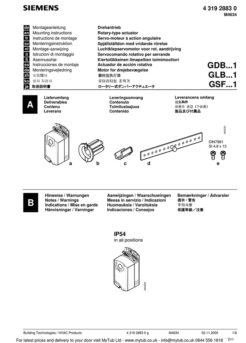
Siemens GDB 1 Series User manual

Siemens

Siemens GDB 1 Series User manual

Siemens SITRANS LUT400 User manual

Siemens

Siemens SITRANS LUT400 User manual

Siemens Reyrolle 7SR45 User manual

Siemens

Siemens Reyrolle 7SR45 User manual

Siemens BACnet ATEC User manual

Siemens

Siemens BACnet ATEC User manual

Siemens N 567/01 User manual

Siemens

Siemens N 567/01 User manual

Siemens SITRANS VP300 User manual

Siemens

Siemens SITRANS VP300 User manual

Siemens SIKOSTART 3RW34 User manual

Siemens

Siemens SIKOSTART 3RW34 User manual

Siemens GHT336.1A/35 User manual

Siemens

Siemens GHT336.1A/35 User manual

Siemens RXB39.1 User manual

Siemens

Siemens RXB39.1 User manual

Siemens instabus JB526C23 User manual

Siemens

Siemens instabus JB526C23 User manual

Siemens ATC5300 User manual

Siemens

Siemens ATC5300 User manual

Siemens Acvatix SAX Series Operator's manual

Siemens

Siemens Acvatix SAX Series Operator's manual

Siemens SIPROTEC 7SJ61 User manual

Siemens

Siemens SIPROTEC 7SJ61 User manual

Siemens SIMATRIX Owner's manual

Siemens

Siemens SIMATRIX Owner's manual

Siemens RLU2 Series User manual

Siemens

Siemens RLU2 Series User manual

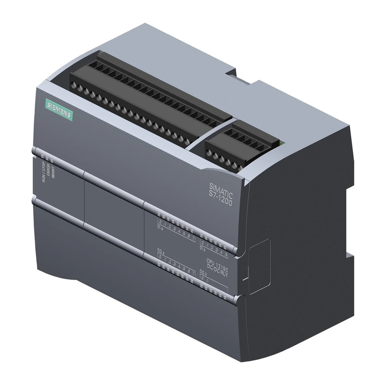
Siemens SIMATIC S7-1200 User manual

Siemens

Siemens SIMATIC S7-1200 User manual

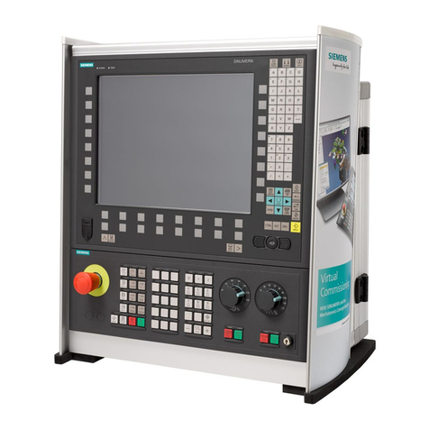
Siemens SINUMERIK 840D sl User manual

Siemens

Siemens SINUMERIK 840D sl User manual

Siemens SSA31.04 User manual

Siemens

Siemens SSA31.04 User manual

Siemens S7-1200 TELECONTROL Instruction Manual

Siemens

Siemens S7-1200 TELECONTROL Instruction Manual

Siemens Simatic S7-300 User manual

Siemens

Siemens Simatic S7-300 User manual

Popular Controllers manuals by other brands

FUTABA CGY760R manual

FUTABA

FUTABA CGY760R manual

AEG THYRO-A operating instructions

AEG

AEG THYRO-A operating instructions

Gilbarco PAM 5000 Quick step guide

Gilbarco

Gilbarco PAM 5000 Quick step guide

GYS GYSPACK AIR manual

GYS

GYS GYSPACK AIR manual

Emerson E300 Series Installation and commissioning guide

Emerson

Emerson E300 Series Installation and commissioning guide

Beckhoff KS2791 Documentation

Beckhoff

Beckhoff KS2791 Documentation

Missouri Wind and Solar 200ECCDIGSSR quick start guide

Missouri Wind and Solar

Missouri Wind and Solar 200ECCDIGSSR quick start guide

Magicar M861A user guide

Magicar

Magicar M861A user guide

Honeywell Experion 8 Series technical information

Honeywell

Honeywell Experion 8 Series technical information

Progeny C4 manual

Progeny

Progeny C4 manual

Sun-Love SR528Q Operation manual

Sun-Love

Sun-Love SR528Q Operation manual

SevenStar D07 Series instruction manual

SevenStar

SevenStar D07 Series instruction manual

OEG KSW-E manual

OEG

OEG KSW-E manual

CRE Technology Gensys Compact Prime Technical documentation

CRE Technology

CRE Technology Gensys Compact Prime Technical documentation

TCS ISW6031-0145 quick start guide

TCS

TCS ISW6031-0145 quick start guide

Savant SmartMedia 6 Quick reference guide

Savant

Savant SmartMedia 6 Quick reference guide

Deif AGC-3 installation instructions

Deif

Deif AGC-3 installation instructions

Arturia Keystep manual

Arturia

Arturia Keystep manual

manuals.online logo
manuals.online logoBrands
  • About & Mission
  • Contact us
  • Privacy Policy
  • Terms and Conditions

Copyright 2025 Manuals.Online. All Rights Reserved.