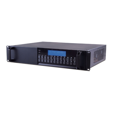
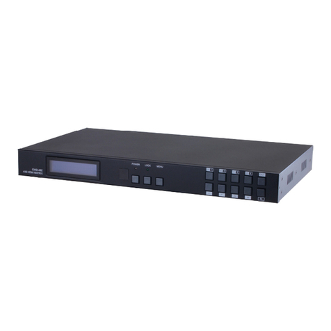
CYP OR-IR88 User manual

OR-IR88
8 x 8 Bi-Directional Infra Red
Matrix Switcher
OPERATION MANUAL

Safety Precautions
Please read all instructions before attempting to unpack or install or
operate this equipment, and before connecting the power supply.
Please keep the following in mind as you unpack and install this
equipment:
Always follow basic safety precautions to reduce the risk of
re, electrical shock and injury to persons.
To prevent re or shock hazard, do not expose the unit to rain,
moisture or install this product near water.
Never spill liquid of any kind on or into this product.
Never push an object of any kind into this product through
module openings or empty slots, as you may damage parts.
Do not attach the power supply cabling to building surfaces.
Do not allow anything to rest on the power cabling or allow it to
be abused by persons walking on it.
To protect the equipment from overheating, do not block the
slots and openings in the module housing that provide
ventilation.
Revision History
Version No Date Summary of Change
RDV1 20110530 Preliminary Release
RDV2 20111013 Front Panel &
Remote Control

Table of Contents
1
1
1
1
1
2
3
3
4
5
6
6
6
7
7
8
10
11
1. Introduction…………………………………………………........……….
2. Applications……………………..…………………………................….
3. Package Contents…………………………......…………….............…
4. System Requirements……...…………………..….…………........…….
5. Features…………………………………………….......……........………
6. Specications..………………………………………...........………...….
7. Hardware Description………………...……........….....................……
7.1 Front Panel ...............................................................................
7.2 Rear Panel …………………………………………..........…….…
8. IR Cable Pin Denitions………………...…….......….....................……
9. Remote Control …….………...................…………..........…..…..…...
9.1 IR Custom Code..........................................................................
9.2 Discrete IR codes for 8x8 HDMI matrix (IR3).............................
10. RS-232 Protocols..................................................................................
10.1 Pin Assignment...........................................................................
10.2 Commands.................................................................................
11. Connection and Installation..................…………..........…..…..…...
12. Acronyms …….………...................…………..........…..…...........…...

1. Introduction
The Bidirectional Infrared 8 by 8 IR Matrix is designed to work with HDMI matrix
together and allow the IR function to control your source devices from beside
your display/source. Using the original remote, you can control DVD/Blu-ray
players, satellite and set-top-boxes and with a cross matrix design this device
gives anyone the ability to send infrared signals from place to place. Simply
place the IR receiver near the display or player and put the IR balster in a po-
sition so that all devices will be able to receive IR signal properly, evenwhen
the sources are hidden in a cabinet or placed far away.
2. Applications
• Control multiple sources and displays
• System Control
• Showroom control
• Long distance IR control
3. Package Contents
• 8 by 8 Bidirectional Infrared Matrix
• Remote Control CR110 with battery
• 5V/2.6A DC power adaptor
• Operation Manual
• 9 IR Receiver cables
• 9 IR Blaster cables
4. System Requirements
Source equipment: Display/ TV/monitors and HDMI/video matrix box devices.
5. Features
• Supports independent IR receiver and IR blaster selection and control
• This device does not send audio/video signals, it only transmits and
receives infra-red signals to control equipment that is far away, using IR
extender cables
• Supports a frequency of 30KHz ~ 50KHz
• Use your existing remote controls
• Supports bidirectionally IR control from display and player side
1

6. Specications
IR Frequency 30KHz to 50KHz
Source Ports 8 x independent IR Blasters; 8 x independent IR Receivers;
1 x All IR blaster control; 1 x All IR receiver control;
TV ports 8 x independent IR Receiver; 8 x independent IR Blaster;
1 x All IR blaster control; 1 x All IR receiver control;
Power Supply 5VDC/2.6A (US/EU standards, CE/FCC/UL certied)
ESD Protection Human body model: ±8kV (air-gap discharge)
±4kV (contact discharge)
Dimensions (mm) 432 (W) x 174 (D) x 44 (H)
Weight(g) 2206
Chassis Material Aluminum
Silkscreen Color Black
Operating Temperature 0˚C~40˚C / 32˚F ~ 104˚F
Storage temperature -20˚C~60˚C / -4˚F ~ 140˚F
Relative Humidity 20~90% RH (non-condensing)
Power Consumption 1W
2

7. Hardware Description
The following sections describe the hardware components of the unit.
7.1 Front Panel
8x8 IR Matrix
IR
Power All Lock Enter
1 2
5 6 7 8
3 4
RS232
AUX
RS232
MAIN
A12345678All
B C D E F G H All
TV SOURCE
DC 5V
Out
In
1 2 3 4 5 6 7
qLCM monitor: This screen will display the IR's source and TV selection
setting.
②IR: This IR window accepts the remote control signal of this device for
control the system.
③Power button & LED: Press this button to turn on the device or press it
again to set it to standby mode. The LED will illuminate in green when the
power is on and red when in standby mode.
④ALL: Press this button to select all TV's IR signal to switch to one Source's IR
signal. The sequence should be pressing All -> Number Key -> Enter.
tLOCK: Press this button to lock all the buttons on the panel and the green
LED will illuminate. To unlock press it again.
⑥ENTER:Pressthisbuttonaftereachandeveryselectiontoconrmthe
setting. If this button is not pressed after 20 seconds the selection will be
cancelled.
⑦1~8 (A~H) Buttons: Press these buttons to select both source and TV's IR
directionpressanumberkeyrst(forTVA~H)andthenpressanumber
keyagain(forSource1~8)andtoconrmtheselectionpressEnter.
3

7.2 Rear panel
8x8 IR Matrix
IR
Power All Lock Enter
1 2
5 6 7 8
3 4
RS232
AUX
RS232
MAIN
A12345678All
B C D E F G H All
TV SOURCE
DC 5V
Out
In
1 2 53 4
qRS-232 AUX: This slot is where you connect the D-Sub 9pin with the desire
device for sending the RS-232 control signal.
②RS-232 MAIN: This slot is where you connect the D-Sub 9pin from the PC/NB
device for the RS-232 signal sending.
③TV In A~H: These slots are to connect with IR receivers for receiving
the IR signal at the TV side and blast out to the designated Source output
through the IR blaster.
TV In All: This slot is to connect with IR receiver for receiving the IR signals
at the TV side and blast out to Source outputs(1~8) through the IR blasters.
TV Out A~H: These slots are to connect with the IR blaster for blasting
out the IR signal received from the designated Source input through the
IR receiver.
TV Out All: This slot is to connect with IR blaster for blasting out the IR signal
received from the Source inputs(1~8) through the IR receivers.
④Source In 1~8: These slots are to connect with IR receivers for receiving
the IR signal at the Source side and blast out to the designated TV
output(s) through the IR blaster(s).
Source In All: This slot is to connect with IR receiver for receiving the IR
signals at the Source side and blast out to the TV outputs(A~H) through
the IR blasters.
Source Out 1~8: These slots are to connect with the IR blaster for blasting
out the IR signal received from the designated TV input(s) through the IR
receiver(s).
Source Out All: This slot is to connect with IR blaster for blasting out the IR
signal received from the TV inputs(A~H) through the IR receivers.
⑤DC 5V: Plug the 5V DC power supply into the unit and connect the
adaptor to an AC outlet.
4

8. IRCablePinDenitions
IR Receiver
① IR signal
② Power 5V
③ Grounding
① ② ③
IR Blaster
① ②
① Power 5V
② IR blaster signal
③ NC
③
Note: Both the IR Receiver & Blaster can support a frequency of
30~50KHz.
5

9. Remote Control
This remote control can be set with multipal format
according to the dipswitch setting. There are total
of four dipswitches with mainly two kinds of settings.
When dipswitches are all set to ON/↑the remote
control is able to control all outputs and all inputs.
For example, when output A wish to select input
5. Press A first and then press 5,
the output A will send and receive input source 5’s
IR signal instantly. Other settings please refer to section 9.2
section where output is based to control
input selections. For example, when all dipswitches
are set to OFF/↓this setting is base on output A
and therefore, it can only control inputs selection.
Hence, when output A wish to selelct input 3 press
3 only will allows output A to receive and send input
source 3’s IR signal. Further setting please refers to
section 9.2.
9.1 IR Custom Code
NO. DATA
1 88
2 89
3 8A
4 8C
5 8D
6 8E
7 90
8 91
9 92
0 95
9.2 Discrete IR codes for 8x8 HDMI matrix (IR3)
Select /
Dipswitch
input
1
input
2
input
3
input
4
input
5
input
6
input
7
input
8
output A ↓↓↓↓ 0cx88 0x89 0x8A 0x8C 0x8D 0x8E 0x90 0x91
output B ↑↓↓↓ 0x88 0x89 0x8A 0x8C 0x8D 0x8E 0x90 0x91
output C ↓↑↓↓ 0x88 0x89 0x8A 0x8C 0x8D 0x8E 0x90 0x91
output D ↑↑↓↓ 0x88 0x89 0x8A 0x8C 0x8D 0x8E 0x90 0x91
output E ↓↓↑↓ 0x88 0x89 0x8A 0x8C 0x8D 0x8E 0x90 0x91
output F ↑↓↑↓ 0x88 0x89 0x8A 0x8C 0x8D 0x8E 0x90 0x91
output G ↓↑↑↓ 0x88 0x89 0x8A 0x8C 0x8D 0x8E 0x90 0x91
output H ↑↑↑↓ 0x88 0x89 0x8A 0x8C 0x8D 0x8E 0x90 0x91
H
8
1A
B
2
3
4D
5E
6F
7G
CR-110
IN OUT
1
2 3
C
6

10. RS-232 Protocols
10.1 Pin Assignment
25IR88 Remote Control Console
PIN Assignment PIN Assignment
1 NC 1 NC
2 Tx 2 Rx
3 Rx 3 Tx
4 NC 4 NC
5 GND 5 GND
6 NC 6 NC
7 NC 7 NC
8 NC 8 NC
9 NC 9 NC
Baud Rate: 9600bps
Data bit: 8 bits
Parity: None
Stop bit: 1
Flow Control: None
7

10.2 Commands
COMMAND ACTION
POWER 00 Power Off (standby)
POWER 01 Power On
PORT 11 Output A select Input1
PORT 12 Output A select Input2
PORT 13 Output A select Input3
PORT 14 Output A select Input4
PORT 15 Output A select Input5
PORT 16 Output A select Input6
PORT 17 Output A select Input7
PORT 18 Output A select Input8
PORT 21 Output B select Input1
PORT 22 Output B select Input2
PORT 23 Output B select Input3
PORT 24 Output B select Input4
PORT 25 Output B select Input5
PORT 26 Output B select Input6
PORT 27 Output B select Input7
PORT 28 Output B select Input8
PORT 31 Output C select Input1
PORT 32 Output C select Input2
PORT 33 Output C select Input3
PORT 34 Output C select Input4
PORT 35 Output C select Input5
PORT 36 Output C select Input6
PORT 37 Output C select Input7
PORT 38 Output C select Input8
PORT 41 Output D select Input1
PORT 42 Output D select Input2
PORT 43 Output D select Input3
PORT 44 Output D select Input4
PORT 45 Output D select Input5
PORT 46 Output D select Input6
8

PORT 47 Output D select Input7
PORT 48 Output D select Input8
PORT 51 Output E select Input1
PORT 52 Output E select Input2
PORT 53 Output E select Input3
PORT 54 Output E select Input4
PORT 55 Output E select Input5
PORT 56 Output E select Input6
PORT 57 Output E select Input7
PORT 58 Output E select Input8
PORT 61 Output F select Input1
PORT 62 Output F select Input2
PORT 63 Output F select Input3
PORT 64 Output F select Input4
PORT 65 Output F select Input5
PORT 66 Output F select Input6
PORT 67 Output F select Input7
PORT 68 Output F select Input8
PORT 71 Output G select Input1
PORT 72 Output G select Input2
PORT 73 Output G select Input3
PORT 74 Output G select Input4
PORT 75 Output G select Input5
PORT 76 Output G select Input6
PORT 77 Output G select Input7
PORT 78 Output G select Input8
PORT 81 Output H select Input1
PORT 82 Output H select Input2
PORT 83 Output H select Input3
PORT 84 Output H select Input4
PORT 85 Output H select Input5
PORT 86 Output H select Input6
PORT 87 Output H select Input7
PORT 88 Output H select Input8
9

HDMI
HDMI
HDMI
HDMI
PU-1109RX
PU-1109RX
1
A
E
F
G
H
A
BPU-1109RX C
PU-1109RX D
B
C
D
4
73 5
6 8
1234
5678
A B C D E F G H 1 2 3 4 5 6 7 8
ACD
E
B
FGH
CAT-6 100m
IR Cable
IR Cable
HDMI Cable HDMI Cable
2
HDMI
HDMI
HDMI
HDMI
HDMI
HDMI
HDMI
HDMI
PU-1109TX
CMIR-882
CMLUX-88S
30°
30°
3M 3M
7M
HDMI
HDMI
HDMI
HDMI
HDMI
HDMI
HDMI
HDMI
11.Connection and Installation
10

1
4
73 5
6 8
1234
5678
A B C D E F G H 1 2 3 4 5 6 7 8
ACD
E
B
FGH
IR Cable
IR Cable
HDMI Cable HDMI Cable
2
HDMI
HDMI
HDMI
HDMI
HDMI
HDMI
HDMI
HDMI
OR-IR88
OR-HD88S
30°
30°
3M 3M
7M
11

20110704 MPM-CMIR-882
Acronyms A
Acronym Complete Term
IR Infrared

www.cypeurope.com
Table of contents
Other CYP Matrix Switcher manuals
Popular Matrix Switcher manuals by other brands

Bluestream
Bluestream CMX44CS user manual

Cable Electronics
Cable Electronics CE Labs HSW44C instruction manual

Cable Electronics
Cable Electronics CE Labs HSW44C instruction manual

Adastra
Adastra RZ45 user manual

Tributaries
Tributaries HM440IR manual

Vision Audio Visual
Vision Audio Visual TECHCONNECT TC-MATRIX owner's manual