Daikin DCM601A72 User manual

iTM plus adaptor
Model
DCM601A72
Installation Manual
01_EN_3P291714-4.indd 1 3/26/2012 5:00:43 PM

Disclosure
To the User in USA
Part 15 of FCC
Note: This equipment has been tested and found to comply with the limits for a Class B
digital device, pursuant to part 15 of the FCC Rules. These limits are designed to provide
reasonable protection against harmful interference in a residential installation. This equip-
ment generates, uses and can radiate radio frequency energy and, if not installed and used
in accordance with the instructions, may cause harmful interference to radio communica-
tions. However, there is no guarantee that interference will not occur in a particular installa-
tion. If this equipment does cause harmful interference to radio or television reception,
which can be determined by turning the equipment off and on, the user is encouraged to
try to correct the interference by one or more of the following measures:
- Reorient or relocate the receiving antenna.
- Increase the separation between the equipment and receiver.
- Connect the equipment into an outlet on a circuit different from that to which the receiver
is connected.
- Consult the dealer or an experienced radio/TV technician for help.
FCC CAUTION
Changes or modications not expressly approved by the party responsible for compliance
could void the user’s authority to operate the equipment.
To the User in CANADA
Canadian ICES-003
This Class B digital apparatus complies with Canadian ICES-003.
Cet appareil numérique de la classe B est conforme à la norme NMB-003 du Canada.
01_EN_3P291714-4.indd 2 3/26/2012 5:00:43 PM

Installation Manual 3P291714-4
DCM601A72 iTM plus adaptor
3
English
“All phases of the eld-installation, including, but not limited to, electrical, piping, safety,
etc. must be in accordance with manufacturer’s instructions and must comply with national,
state, provincial and local codes”
Read these SAFETY CONSIDERATIONS carefully before installing the controller.
After completing the installation, ensure that the unit operates properly during the startup
operation.
Train the customer to operate and maintain the unit. Inform customers that they should
store this Installation Manual with the Operation Manual for future reference.
Always use a licensed installer or contractor to install this product. Improper installation
can result in water or refrigerant leakage, electrical shock, re, or explosion.
Meanings of WARNING, CAUTION, and NOTE Symbols.
WARNING Indicates a potentially hazardous situation which, if not
avoided, could result in death or serious injury.
CAUTION Indicates a potentially hazardous situation which, if not
avoided, may result in minor or moderate injury.
It may also be used to alert against unsafe practices.
NOTE Indicates situations that may result in equipment or prop-
erty-damage accidents only.
WARNING
•Only qualied personnel must carry out the installation work.
•Consult your Daikin dealer regarding relocation and reinstallation of the con-
troller.
Improper installation work may result in leakage, electric shocks or re.
•Install the controller in accordance with the instructions in the installation man-
ual.
Improper installation may cause electrical shocks or re.
•Use only specied accessories and parts for installation work.
Failure to use specied parts may result in water leakage, electric shocks, re, or the
unit falling.
•Do not disassemble, reconstruct, or repair.
Electric shock or re may occur.
•Make sure that all wiring is secured, that specied wires are used, and that no
external forces act on the terminal connections or wires.
Improper connections or installation may result in re.
•Before touching electrical parts, turn off the unit.
Safety Considerations
01_EN_3P291714-4.indd 3 3/26/2012 5:00:44 PM

4
Installation Manual 3P291714-4
DCM601A72 iTM plus adaptor
English
CAUTION
•Keep water out of the controller.
•To avoid leakage and electric shock due to entry of water or insects, ll the wir-
ing through-hole with putty.
•Do not wash the controller with water as it may result in electrical shocks or
re.
•Do not touch the controller buttons with wet ngers.
Touching the buttons with wet ngers can cause an electric shock.
•Do not install the controller in the following locations:
(a) Where a mineral oil mist or oil spray or vapor is produced, for example, in a
kitchen.
Plastic parts may deteriorate and fall off or result in water leakage.
(b) Where corrosive gas, such as sulfurous acid gas, is produced.
Corroding copper pipes or soldered parts may result in refrigerant leakage.
(c) Near machinery emitting electromagnetic waves.
Electromagnetic waves may disturb the operation of the control system and cause
the unit to malfunction.
(d) Where ammable gas may leak, where there is carbon ber or ignitable dust
suspensions in the air, or where volatile ammables such as thinner or gaso-
line are handled.
Operating the unit in such conditions can cause a re.
(e) High temperature area or directly amed point.
Heating and/or re can occur.
(f) Moist area, where there is exposure to water.
If water enters the inside of the controller, it may cause electric shock and electrical
components may fail.
NOTE
•Install the control wires for the controller at least 3.5 feet (1 meter) away from
televisions or radios to prevent image interference or noise.
Depending on the radio waves, a distance of 3.5 feet (1 meter) may not be sufcient
to eliminate the noise.
•If water enters inside of the controller, electric shock may be caused and inner
electronics may fail.
01_EN_3P291714-4.indd 4 3/26/2012 5:00:44 PM

Installation Manual 3P291714-4
DCM601A72 iTM plus adaptor
5
English
Contents
1 Before Installation ................................................................................................... 7
1.1 Checking that all accessories are included ................................................................................ 7
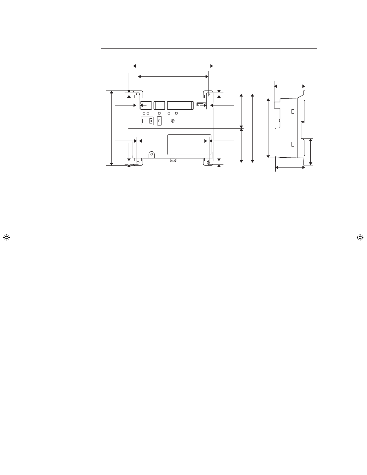
1.2 Understanding external dimensions .......................................................................................... 8
1.3 Understanding where terminals are located .............................................................................. 8
1.3.1 Front face of iTM plus adaptor ......................................................................................... 8
1.4 Determining installation place .................................................................................................. 10
1.4.1 Installation place and mounting direction ...................................................................... 10
1.4.2 Required space ............................................................................................................. 10
1.4.3 Environmental conditions .............................................................................................. 11
2 Connection ............................................................................................................. 12
2.1 Connecting intelligent Touch Manager ..................................................................................... 13
2.1.1 Terminals location and conceptual connection diagram ................................................ 13
2.1.2 Requirements that must be met .................................................................................... 13
2.1.3 Address setup and termination resistor ......................................................................... 14
2.2 Connecting DIII-NET-compatible air conditioning equipment ................................................... 15
2.2.1 Terminals location and conceptual connection diagram ................................................ 16
2.2.2 Requirements that must be met .................................................................................... 17
2.2.3 Precautions for using multiple centralized controllers.................................................... 17
2.3 Connecting contact or pulse input equipment such as electric energy meters ........................ 18
2.3.1 Terminals location and conceptual connection diagram ................................................ 19
2.3.2 Requirements that must be met .................................................................................... 19
2.4 Connecting power supply ........................................................................................................ 20
2.4.1 Terminals location and conceptual connection diagram ................................................ 20
2.4.2 Requirements that must be met .................................................................................... 21
3 Installation .............................................................................................................. 22
3.1 Screw mounting to control enclosure ....................................................................................... 22
3.1.1 Dimensions of iTM plus adaptor .................................................................................... 22
3.1.2 Installation procedure .................................................................................................... 23
3.2 DIN rail mounting ..................................................................................................................... 23
3.2.1 Removal from DIN rail ................................................................................................... 24
4 Assigning a DIII-NET address for each air conditioner ...................................... 25
4.1 Remote controller buttons and areas....................................................................................... 25
4.1.1 Procedure for a wired remote controller ........................................................................ 26
4.1.2 Procedure for a navigation remote controller................................................................. 28
4.1.3 Setting an unique address to each unit (when power distribution is enabled) ............... 30
01_EN_3P291714-4.indd 5 3/26/2012 5:00:44 PM

6
Installation Manual 3P291714-4
DCM601A72 iTM plus adaptor
English
5 Outdoor Unit Address Setup ................................................................................ 31
5.1 Procedure ................................................................................................................................ 31
6 Quick Operation Guide ......................................................................................... 32
6.1 Viewing target area and management point information in list format ..................................... 32
6.2 Viewing target areas and management points ........................................................................ 32
6.3 Starting/stopping an area or management point ..................................................................... 33
01_EN_3P291714-4.indd 6 3/26/2012 5:00:44 PM

Installation Manual 3P291714-4
DCM601A72 iTM plus adaptor
7
English
1 Before Installation
Before you start installing the iTM plus adaptor, complete the following checks:
•Check that the iTM plus adaptor comes with all accessories.
•Understand where the terminals and switches of the iTM plus adaptor are located.
•Make sure that an appropriate space for installing the iTM plus adaptor is available.
1.1 Checking that all accessories are included
Based on the following accessory list, check that all accessories for the iTM plus adaptor
are included. Should there be any missing or defective parts, contact your dealer.
<Accessories included with iTM plus adaptor>
A B
C
D
d-2
d-1
a-1
b-1
c-1
A (a-1) iTM plus adaptor body (1 pc.)
B (b-1) Round-head wood screw (φ3.5×16), 4 pcs.
C (c-1) Cable tie, 1 pc.
D (d-1) Installation manual (This manual), 1 pc. (d-2) Manual CD, 1 pc.
01_EN_3P291714-4.indd 7 3/26/2012 5:00:44 PM

8
Installation Manual 3P291714-4
DCM601A72 iTM plus adaptor
English
1.2 Understanding external dimensions
•iTM plus adaptor body
5-7/8
4-23/32
5-11/32
2-11/162-21/32
2-1/16
6-5/16
2-13/32
2-13/32
(in.)
1/4 1/4
5/32
5/32
1/4
5/32
1/4
5-1/2
5/32
1.3 Understanding where terminals are located
Understand the arrangement of terminals and switches on the unit and draw up an ef-
cient work plan. For connection details including the cable type, terminal size, and wiring
precautions, refer to “2. Connection”.
1.3.1 Front face of iTM plus adaptor
All the terminals used during installation are located on the front face of the iTM plus
adaptor. Note that only the power terminals are covered with a terminal cover for safety.
You can remove this cover by loosening a single screw.
In addition to these terminals, several switches and LEDs are also located on the front
face of the iTM plus adaptor.
01_EN_3P291714-4.indd 8 3/26/2012 5:00:44 PM

Installation Manual 3P291714-4
DCM601A72 iTM plus adaptor
9
English
<Front face of iTM plus adaptor>
A
FI
J K L M N
G H
B C D
POWER
100-240V
~
50/60Hz
LN
E
A [plus ADP IF] The terminals for connecting an intelligent Touch Manager or iTM plus
adaptor installed in parallel.
B [DIII] The communication line connection terminals for “DIII-NET”, which enables
communications with DAIKIN’s air conditioning equipment.
C [Di] The terminals for connecting an external signal input device for stopping air con-
ditioners in an emergency, or for connecting electric energy meters for calculating the
electricity usage of individual indoor air conditioning units.
D [RESERVE] No Use.
E [POWER] The power line connection terminals. These terminals are covered with a
protective cover. A power supply voltage of 24 VAC (at 60 Hz) is required. Near this
terminal block, there is a blue resin cable mount used for securing the power supply
cables with cable ties.
F [plus ADP ADDRESS] The switch for selecting the address of the iTM plus adaptor.
For each iTM plus adaptor, set a unique number between 2 to 8.
G [TERM] The switch used when multiple iTM plus adaptors are connected in parallel
for enabling the termination resistor on the furthest iTM plus adaptor from the intelli-
gent Touch Manager.
H [DIII MASTER] The switch used when there are two or more DIII-NET centralized
controllers, such as intelligent Touch Managers, are connected for distinguishing
between the “MASTER” or the “SLAVE” controllers.
I [RESET//] The switch for restarting the iTM plus adaptor.
J [Tx] (Green) The indicator that indicates when on that data is being sent to the intel-
ligent Touch Manager.
K [Rx] (Orange) The indicator that indicates when on that data is being received from
the intelligent Touch Manager.
L [DIII MONITOR] (Yellow) The indicator that indicates when on that data is being com-
municated with DIII-NET.
M [CPU ALIVE] (Green) The LED that indicates that the CPU is operating normally. For
the relationship between the LED status and the unit’s operating condition, refer to
the “LED status and operation” table below.
N [ALARM] (Red) The LED that turns on or blinks in the event of an error. For the rela-
tionship between the LED status and the unit’s operating condition, refer to the “LED
status and operation” table below.
01_EN_3P291714-4.indd 9 3/26/2012 5:00:44 PM

10
Installation Manual 3P291714-4
DCM601A72 iTM plus adaptor
English
The table below shows the status of the CPU ALIVE/ALARM LED when the iTM plus
adaptor is operating normally or failed.
NOTE
[LED status and operation table]
Operating condition CPU ALIVE ALARM
Normal Blink Off
Hardware failure Off On
Address failure On On
plus ADP IF communication failure On Blink
1.4 Determining installation place
Be sure to install the iTM plus adaptor in a place that meets the conditions described in
1.4.1 through 1.4.3.
1.4.1 Installation place and mounting direction
Note that the iTM plus adaptor must be installed in a place and in a mounting direction as
described below:
•Installation place: Indoor, inside control enclosure (which must be lockable or designed
to be opened only with a special tool)
•Mounting direction: Vertical only
1.4.2 Required space
To install the iTM plus adaptor, the following space is required. Also note the following:
•Make sure that there is a minimum clearance of 25/32 in. between each unit and wiring
ducts.
•When installing two or more units side by side, they can be arranged without clearance
in the horizontal direction.
Required installa-
tion space
1-9/16
1-9/16
25/32
25/32
25/32
(in.)
A
A
6-5/16
5-7/8
A Wiring duct
01_EN_3P291714-4.indd 10 3/26/2012 5:00:45 PM

Installation Manual 3P291714-4
DCM601A72 iTM plus adaptor
11
English
1.4.3 Environmental conditions
The installation environment must meet the following conditions:
•Ambient temperature: 14 to 122 °F
•Ambient humidity: 85% RH or less (without condensation)
01_EN_3P291714-4.indd 11 3/26/2012 5:00:45 PM

12
Installation Manual 3P291714-4
DCM601A72 iTM plus adaptor
English
2 Connection
This chapter describes the procedure for connecting the iTM plus adaptor with intelligent
Touch Manager, DIII-NET-compatible air conditioning devices and other equipment.
In addition to air conditioners, the iTM plus adaptor can be connected and work with a
wide range of equipment. However, the required connection procedures vary depending
on the equipment to be connected.
Required proce-
dures
•2.1 Connecting intelligent Touch Manager
•2.2 Connecting DIII-NET-compatible air conditioning equipment
•2.4 Connecting power supply
Equipment-spe-
cic procedures
•2.3 Connecting contact or pulse input equipment such as electric energy meters
WARNING
•Do not turn the power supply on until all connections are made. Not doing so
may cause an electric shock.
•After completing connections, check again that all wires are connected cor-
rectly before turning on the power supply.
•All eld supplied parts and materials, electric works must conform to local
codes.
•All wiring must be performed by an authorized electrician.
CAUTION
Provide a cable trap before the terminal block and perform wiring to prevent
water entry. Water splashing onto the terminal block may result in an electric
shock or re.
B
A
C
A Terminal block
B With trap
C Without trap
01_EN_3P291714-4.indd 12 3/26/2012 5:00:45 PM

Installation Manual 3P291714-4
DCM601A72 iTM plus adaptor
13
English
2.1 Connecting intelligent Touch Manager
The iTM plus adaptor is a device that enables you to control more air conditioners with the
intelligent Touch Manager. It needs to be connected to an intelligent Touch Manager to
provide this capability.
2.1.1 Terminals location and conceptual connection diagram
Connect the terminals located in the “plus ADP IF” section of the iTM plus adaptor to the
corresponding terminals located in the “plus ADP IF” section on the rear face of your intel-
ligent Touch Manager. Note that these terminals have polarity. Be sure to connect the
positive wire to the “+” terminal and the negative wire to the “–” terminal, respectively.
In addition, the intelligent Touch Manager must be connected as a terminal to the wiring.
<Terminals location and conceptual connection diagram>
A intelligent Touch Manager (Rear face)
B iTM plus adaptor
C plus ADP IF (intelligent Touch Manager)
D plus ADP IF (iTM plus adaptor)
E iTM plus adaptor on which termination resistor must be enabled
2.1.2 Requirements that must be met
•Cable type: CPEV or FCPEV cable
•Core thickness: AWG22-19
•Cable length: 164 ft. or less in total for overall plus ADP IF wiring
01_EN_3P291714-4.indd 13 3/26/2012 5:00:45 PM

14
Installation Manual 3P291714-4
DCM601A72 iTM plus adaptor
English
2.1.3 Address setup and termination resistor
You need to assign a unique address to each of your intelligent Touch Manager and the
iTM plus adaptors connected to it. Because the address of the intelligent Touch Manager
is xed to “1”, each iTM plus adaptor must be given an address between “2” and “8”. Turn
the plus ADP ADDRESS switch located on the front face of each iTM plus adaptor to set
a unique address.
You also need to enable the termination resistor on the furthest iTM plus adaptor from the
intelligent Touch Manager. This termination resistor setting is done using the TERM switch
located on the front face of the iTM plus adaptor.
<plus ADP ADDRESS switch and TERM switch>
NOTE
If the two LEDs, CPU ALIVE and ALARM, both light up during power-on after installa-
tion, there is a possibility of a problem with the address assignment:
•An invalid address is set. (“0”, “1”, and “9” are not allowed.)
•A duplicate address is used.
You must assign a unique address between 2 and 8 for each iTM plus adaptor. Power
off the unit once, check and correct the address, and then turn it on again.
Check the status of the two LEDs, CPU ALIVE and ALARM.
01_EN_3P291714-4.indd 14 3/26/2012 5:00:45 PM

Installation Manual 3P291714-4
DCM601A72 iTM plus adaptor
15
English
2.2 Connecting DIII-NET-compatible air conditioning equipment
DIII-NET is a unique air conditioning equipment communication capability developed by
DAIKIN. Using DIII-NET, you can centrally control multiple DIII-NET-compatible air condi-
tioning devices by connecting them to your intelligent Touch Manager.
The iTM plus adaptor allows you to connect additional 64 groups of air conditioners per
unit. Considering that the intelligent Touch Manager can be connected with a maximum of
seven iTM plus adaptors, you can control a total of 512 groups of air conditioners at a
maximum using a single intelligent Touch Manager.
WARNING
•Be sure to perform this procedure with the power supply turned off. Not doing
so may cause an electric shock.
•The maximum length of adhered wiring of high current electrical line of power
wires and weak current line of communication wires must be kept to 65 ft. or
less.
NOTE
Each air conditioner controlled via an iTM plus adaptor is also assigned a DIII address
between “1-00” to “4-15”. From the intelligent Touch Manager, it is recognized as “2:1-
00”, “3:1-02”, or the like, with the DIII-NET port number prexed.
01_EN_3P291714-4.indd 15 3/26/2012 5:00:45 PM

16
Installation Manual 3P291714-4
DCM601A72 iTM plus adaptor
English
2.2.1 Terminals location and conceptual connection diagram
To connect the DIII-NET communication line, use the two terminals F1 and F2 under the
label “DIII”. These 2 terminals have no polarity. An example of connecting more than 2 air
conditioning devices is shown in the following conceptual connection diagram.
CAUTION
Make sure that the wires you are connecting to the F1 and F2 terminals are not
power wires. Inadvertently connecting power wires to these terminals results in
a failure of the air conditioner or iTM plus adaptor.
<Conceptual connection diagram with air conditioning equipment>
F2F1
F1, F2 P1, P2 F1, F2 P1, P2F1, F2 P1, P2F1, F2 P1, P2F1, F2 P1, P2
F1, F2 F1, F2
F1, F2 P1, P2 F1, F2 P1, P2F1, F2 P1, P2F1, F2 P1, P2F1, F2 P1, P2
F1, F2 F1, F2
E
F
A
B C D D D D D
A
B C D D D D D
A Outdoor unit
B OUT - OUT
C IN - OUT
D Indoor unit
E A maximum of 16 indoor units can be connected per remote controller group.
F A maximum of 64 remote controller groups (128 indoor units) can be connected.
A maximum of 64 indoor units can be connected when power distribution is enabled.
01_EN_3P291714-4.indd 16 3/26/2012 5:00:45 PM

Installation Manual 3P291714-4
DCM601A72 iTM plus adaptor
17
English
NOTE
•What’s a remote controller group?
A single remote controller can simultaneously control a maximum of 16 indoor units.
This capability is referred to as group control. A remote controller group is a group of
indoor units controlled under the same remote controller.
[Conceptual drawing of a remote controller group]
F1, F2 P1, P2 F1, F2 P1, P2 F1, F2 P1, P2 F1, F2 P1, P2
A
A Max. 16 units
2.2.2 Requirements that must be met
Cable specica-
tions
•Cable type: 2-core vinyl-insulated vinyl-sheathed cable/vinyl cabtyre cable or 2-core
shielded cable
•Core thickness: AWG18-16
•Terminal treatment: Use a round crimp-type terminal (M3) with insulating sleeve.
Precautions •Do not use multicore cables with three or more cores.
•When using a shielded cable, connect only one end of each steel wire to the ground.
•Keep the DIII-NET communication wiring at least 1-31/32 in. away from power supply
wiring.
•The maximum wire distance must be kept to 3280 ft. or less. The total wire length must
be limited to 6561 ft., except when using a shielded cable whose total wire length must
be kept to 4921 ft. or less.
2.2.3 Precautions for using multiple centralized controllers
Equipment that controls multiple air conditioners is referred to as “centralized controller”.
DAIKIN’s product portfolio includes a wide range of centralized controllers suited to differ-
ent applications or target sizes, which can be used in combination to construct an optimal
air conditioning system.
If two or more centralized controllers are used in combination in DIII-NET, you must estab-
lish a MASTER to SLAVE relationship among those controllers to prevent confusion. The
MASTER authority may be assigned to one controller only. The remaining controllers must
be set to SLAVE.
The iTM plus adaptor is set to MASTER by default. Change the setting to SLAVE in any of
the following cases:
•Where Interface for use in BACnet is installed in parallel.
•Where Interface for use in LONWORKS is installed in parallel.
•Where there is another MASTER intelligent Touch Manager, or it is connected in rela-
tions of main/sub.
•Where there is another MASTER iTM plus adaptor, and it is connected in relations of
main/sub.
01_EN_3P291714-4.indd 17 3/26/2012 5:00:46 PM

18
Installation Manual 3P291714-4
DCM601A72 iTM plus adaptor
English
<DIII MASTER>
To set the iTM plus adaptor to SLAVE, use the DIII
MASTER switch.
Placing the switch in the upper position (labeled as
“SLAVE”) changes it to a SLAVE.
SLAVE
MASTER
To install multiple centralized controllers, set only the highest priority controller to MAS-
TER and all other controllers to SLAVE according to the following order of priority:
High
(1) Interface for use in BACnet
(2) Interface for use in LONWORKS
(3) intelligent Touch Manager (Main), iTM plus adaptor (Main)
(4) Central Remote Controller (Main)
(5) intelligent Touch Manager (Sub), iTM plus adaptor (Sub)
(6) Central Remote Controller (Sub)
(7) ON/OFF Controller (Main)
(8) ON/OFF Controller (Sub)
Priority
Low
Centralized con-
trollers that cannot
be installed in
parallel with iTM
plus adaptor
•CALCULATE UNIT
•intelligent Processing Unit
•Parallel Interface
•Intelligent Touch Controller
•DIII-NET Plus Adapter
•Residential Central Remote Controller
•Schedule Timer
•Wiring Adaptor for Electrical Appendices (1) (KRP2)
2.3 Connecting contact or pulse input equipment such as elec-
tric energy meters
The iTM plus adaptor can be connected with an external signal input device for stopping
air conditioners in an emergency, or with electric energy meters for calculating the elec-
tricity usage of individual air conditioners (when power distribution is enabled).
WARNING
•Be sure to perform this procedure with the power supply turned off. Not doing
so may cause an electric shock.
•Do not clamp the cables with high-current lines such as a power cable.
NOTE
Power distribution is available for a maximum of 64 air conditioners (indoor units) per
DIII-NET port.
01_EN_3P291714-4.indd 18 3/26/2012 5:00:46 PM

Installation Manual 3P291714-4
DCM601A72 iTM plus adaptor
19
English
2.3.1 Terminals location and conceptual connection diagram
Use the terminals located under the label “Di” to connect the pulse signal line. The iTM
plus adaptor accepts four types of signals through its four channel terminals, Di1, Di2, Di3,
and Di4, and two COM terminals (ground).
<Conceptual drawing of Di connec-
tion>
NOTE
The COM terminals are all connected internally.
So, you can use either of them.
However, you can connect up to two wires
simultaneously to each COM terminal.
Di1 Di2 COM Di3 Di4 COM
2.3.2 Requirements that must be met
•Cable type: CPEV cable
•Core thickness: AWG22-19
•Cable length: 656 ft. or less <Pulse width>
•Pulse width: 20 to 400 ms
Pulse interval: 100 ms or more
A
B
A Pulse width: 20 to 400 ms
B Pulse interval: 100 ms or more
CAUTION
•The contact connected to the contact input terminal must be capable of han-
dling 10 mA at 16 VDC.
•If an instantaneous contact is used for triggering an emergency stop, use one
that has an energization time of 200 ms or more.
•Do not clamp the cables with high-current lines such as a power cable.
01_EN_3P291714-4.indd 19 3/26/2012 5:00:46 PM

20
Installation Manual 3P291714-4
DCM601A72 iTM plus adaptor
English
2.4 Connecting power supply
Connect the iTM plus adaptor to an AC power supply.
WARNING
The following procedures must be carried out with the power supply shut off. Do
not turn the power supply on until all connections are made. Not doing so may
cause an electric shock.
2.4.1 Terminals location and conceptual connection diagram
<Removing terminal cover>
For safety reasons, power connection terminals are
covered with a protective cover. Remove this cover
before you start connecting the power supply. You
can do so by loosening a single screw using a Phil-
lips screwdriver.The terminal cover must be replaced
where it was before when you nish connecting the
power supply.
Next, connect the power supply to the three terminals, L (Live), N (Neutral), and ground in
the POWER section. Be sure to ground the ground terminal. Remember to secure the
power cables to the blue resin cable mount with cable ties when power connections are
made.
<Connecting power supply>
D
B
LN
C
A
E
F
A Cable mount
B Earth leakage breaker
C Power supply (24VAC, 60Hz)
D Earth
E Secure cables with cable ties.
F Location of cable mount
01_EN_3P291714-4.indd 20 3/26/2012 5:00:46 PM
Table of contents
Other Daikin Adapter manuals

Daikin
Daikin BRP069A61 How to use

Daikin
Daikin BRP069C81 User manual

Daikin
Daikin BRP069A41 User manual

Daikin
Daikin BRP069C41 How to use

Daikin
Daikin BRP069B41 User manual

Daikin
Daikin 4P359542-4R User manual

Daikin
Daikin BRP069C41 User manual

Daikin
Daikin BRP069A78 How to use

Daikin
Daikin BRP072B42 User manual

Daikin
Daikin 4P359542-3S User manual

Daikin
Daikin BRP069A61 User manual

Daikin
Daikin BRP069C51 User manual

Daikin
Daikin BRP069A71 How to use

Daikin
Daikin BRP084C42 User manual

Daikin
Daikin 4P359542-1E User manual

Daikin
Daikin BRP069A61 How to use

Daikin
Daikin EKMBPP1 User manual

Daikin
Daikin 4P359542-1S User manual

Daikin
Daikin BRP069B82 User manual

Daikin
Daikin BRP069A61 User manual