Daikin BRP072B42 User manual

Wireless LAN Connecting Adapter
[BRP072B42]Installation Manual


1
Wireless LAN Connecting Adapter
[BRP072B42]Installation Manual
Check if the following accessories are included in your package.
Website:
http://www.daikinthai.com/wlan3/modbus
This set includes the following items:
Wireless LAN connecting adapter: 1 pc,
Serial number sticker (*1): 1 pc,
Screw (M3 × 8): 2 pcs.
Installation manual: 1 pc
This set includes the following items:
Holder: 1 pc,
Double face tape: 2 pcs,
Screw (M3 × 16): 2 pcs.
Wire harness assembly (*2): 1 pc
•For details on specifications, setting methods, FAQ, and the latest
version of this manual, see our website.
Accessories
Accessories
•Do not use the Wireless LAN connecting adapter for purposes other than wireless LAN
communication. Not accessible to Internet networks.
*1 •The serial number sticker is necessary for wireless connection settings.
Please keep it in a safe place.
*2 •Do not use extension or other wire harness assembly.
•Some models already have this wire harness assembly installed in the indoor unit.
AB
D
C

2
The protection of appliances marked with this symbol is ensured by double
insulation and does not require a safety connection to electrical earth (ground).
When installing:
Situations which could result in death
or serious injury.
WARNING
•The following describes the meanings of pictorial symbols used in this installation manual.
•To conduct a test run of the air conditioner, complete according to the installation manual for
the air conditioner unit.
Give this installation manual to the customer when installation is completed.
Prohibited Follow directions
Safety precautions
Safety precautions
Request installation by your dealer or a technician.
(Could cause electric shock or fire.)
Always use the accessories and specified parts for installation. Be sure to follow
the directions in this installation manual.
(Could cause the unit to fall, electric shock or fire.)
Electrical work must be performed in accordance with relevant local and national
regulations and with the instructions in this installation manual.
Always use a dedicated circuit.
(Could cause electric shock or fire.)
Always turn off the power supply when installing.
(Touching the electrical parts could cause an electric shock.) The main switch of
the installation is at the outdoor unit. Please switch off this main switch to turn off
the power supply.

3
Situations which could result in death or
serious injury.
WARNING
When using:
Do not disassemble, modify, or repair.
(Could cause fire, electric shock or injury.)
Do not handle the Wireless LAN connecting adapter with wet hands.
(Could cause electric shock or fire.)
Do not allow the Wireless LAN connecting adapter to get wet or use it when
bathing or similar activities using water.
(Could cause electric shock or fire.)
Do not use the Wireless LAN connecting adapter near medical equipment or
persons using cardiac pacemakers or defibrillators. The Wireless LAN connecting
adapter may cause life-threatening electromagnetic interference.
Do not use the Wireless LAN connecting adapter near auto-control equipment
such as automatic doors or fire alarm equipment.
(Could cause accidents due to erroneous equipment behavior.)
Immediately turn off the circuit breaker if there is abnormal odor or sound,
when it is overheating, or smoking.
(Could cause fire or malfunction.)
•Request an inspection by your dealer.
Turn off the circuit breaker if the Wireless LAN connecting adapter was dropped
or the case is damaged.
(Could cause fire or electric shock.)
•Request an inspection by your dealer.
Safety precautions
Safety precautions

4
Situations which could result in damage or
physical injury.
CAUTION
When installing:
Do not install where flammable gas leaks can occur.
(Could cause fire.)
Grip the connector when disconnecting the wire harness assembly from the outlet.
(Otherwise fire or electric shock can occur.)
Do not use where small children can get access.
(Could cause injuries.)
When using:
Do not use this product near a microwave oven.
(This can affect Wireless LAN communications.)
Safety precautions
Safety precautions

5
Wireless LAN connecting adapter
Wireless LAN connecting
adapter (External)
Main components
Main components
Basic parameters:
Frequency range:
Radio protocol:
RF channel:
Output power:
ERP:
Power supply:
2400 MHz–2483.5 MHz
IEEE 802.11b/g/n
1–13
0 dBm~18 dBm
17 dBm (11b) / 13 dBm (11g) / 12 dBm (11n)
DC 14 V / 100 mA
RF channel: Radio frequency channel
ERP: Effective radiated power
Applicable indoor units
For more details about installation of Wireless LAN connecting adapter
and applicable units visit http://www.daikinthai.com/wlan3/modbus
RUN lamp (orange)
lights when connecting to a router
(Wireless LAN access point).
AP lamp*
SETUP button
Use when connecting to a router
(Wireless LAN access point).
MODE button*
POWER button*
Installation type
Installation type
Wireless LAN connecting adapter
(the product is inside the indoor unit)
B
A
* No operation for BRP072B42 model.

6
Installation
Installation
Choose an installation site. (In the case of )
The Wireless LAN connecting adapter should be sited in a place where:
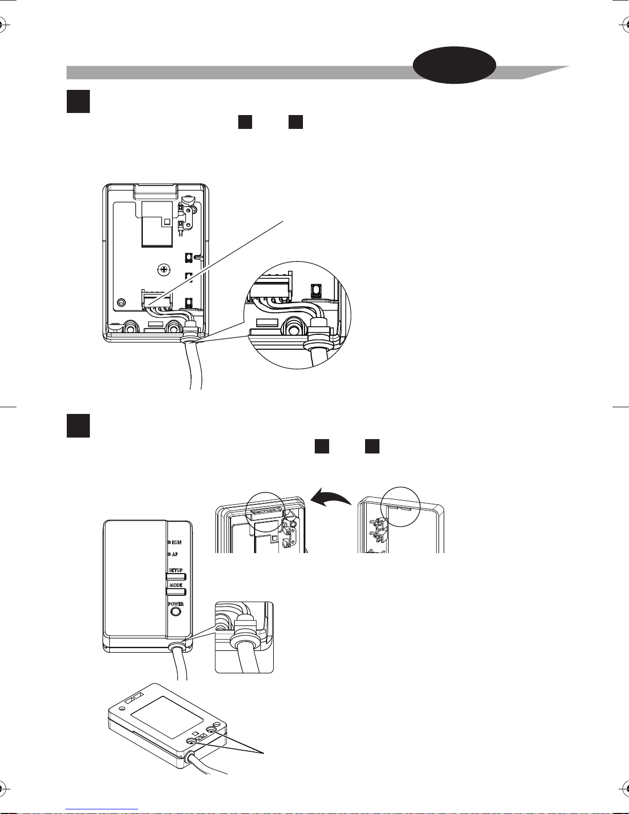
Attach the Wireless LAN connecting adapter to indoor unit.
Always turn off the power supply when installing.
(Touching the electrical parts could cause an electric shock.)
The main switch of the installation is at the outdoor unit.
WARNING
Installation
Work
1
2
•
The
Wireless LAN connecting
adapter is not in the path of direct sunlight.
•
The
Wireless LAN connecting
adapter is away from the source of heat or steam.
•
There is not source of machine oil vapour (this may shorten
the Wireless LAN connecting
adapter
life).
•
The
Wireless LAN connecting
adapter is at least 1 m away from any television or radio set
(The Wireless LAN connecting adapter may cause interference with the picture or sound).
•Distance between the indoor unit and the Wireless LAN connecting adapter is within length
of Wireless LAN cable.
Always turn off the power supply when installing.
(Touching the electrical parts could cause
an electric shock.)
Danger
•
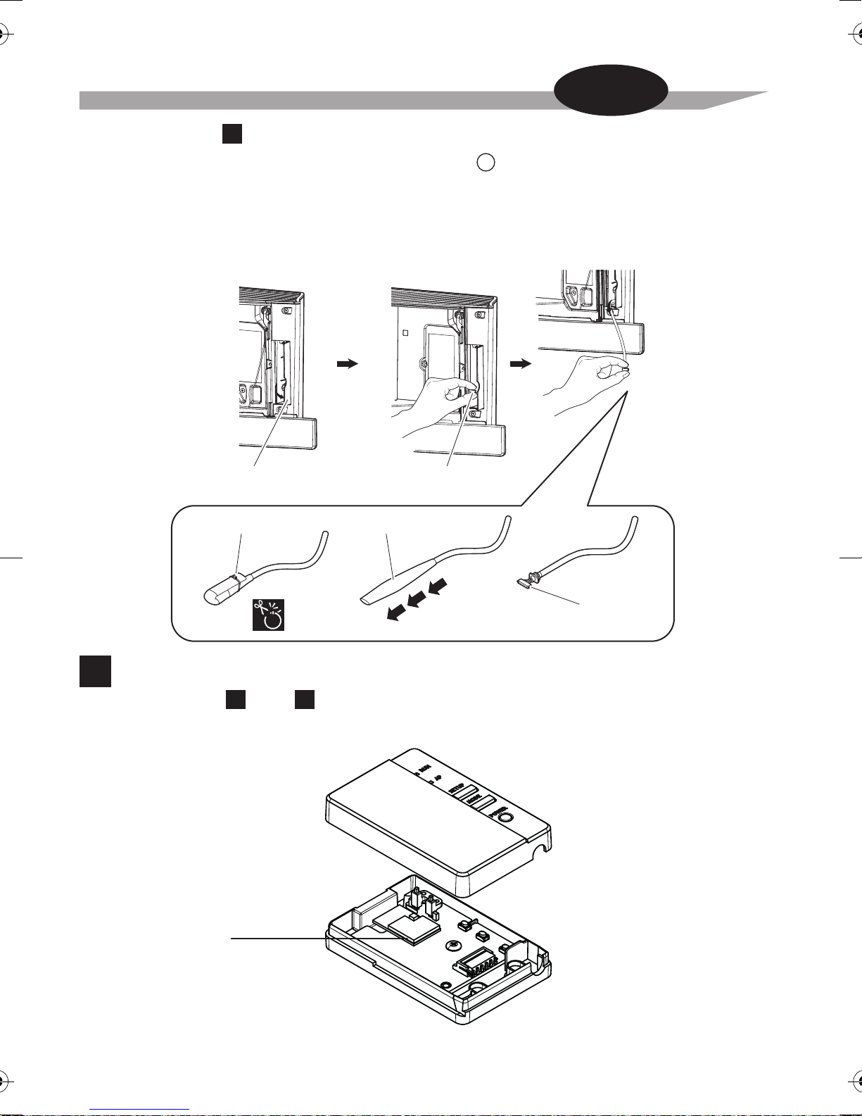
If there is no white“S21” connector,
install aseparate printed circuit board
intothe indoor unit.
Connect the end of the connector
without the
wire harness
anchor.
Connector
Attach wire harness assembly to
indoor unit.
Remove the front grille of the indoor unit,
then connect the connector of wire harness assembly
to the white “S21” connector on the electrical wiring box.
• For instructions on how to remove the front grille or run the
wire harness assembly
into place,
see the installation manual of the particular air conditioner.
(
Wire harness assembly
can connect to
wire harness assembly
HA.)
D
Wire harness anchor
Wire harness
assembly
D
D
D
The steps to be followed depend on the installation type: type = External, type = Internal.
A B
A
In the case of A
D

7
Installation
Installation
Installation
Work
3
Remove the Wireless LAN connecting adapter case (upper).
Remove the upper case of the Wireless LAN connecting adapter.
Wireless LAN
connecting adapter
printed circuit board
Wireless LAN connecting
adapter case (upper)
Wireless LAN connecting
adapter case (lower)
Open the door Grab the
wire harness assembly
Binding band Insulation tube
Connector
(white)
D
•
Some models already have the wire harness assembly
installed in the indoor unit.
In such a case,
please proceed with the installation as below.
Remove the upper front panel from the indoor unit and open the door, grab the wire harness
assembly with your fingers and pull it out, then remove the binding band and pull the insulation
tube off the wire harness assembly.
• Refer to your air conditioner’s installation manual for details on removing the upper front panel.
In the case of B
(For both and .)
A B

8
Attach wire harness assembly to the Wireless LAN connecting
4
Installation
Installation
Installation
Work
Attach the
wire harness assembly
connector (white).
•
Fasten the wire harness assembly to the notch in the Wireless LAN connecting adapter case (lower).
Connect the connector to the same color.
Fasten the
wire harness assembly
and ensure that external force is not transmitted.
Connector (white)
Return the Wireless LAN connecting adapter case
to its original state. (For both and .)
Snap the top of the upper case unto the clip at the top of the lower case
and press to close the box.
5
Fix the upper Wireless LAN connecting adapter
case with 2 screws (M3 × 8) located in accessory set.
Wireless LAN connecting
adapter case (lower)
top portion clip
Wireless LAN connecting
adapter case (upper)
top portion clip
Check that the
wire harness assembly
is securely fastened.
adapter. (For both and .)
A B
A B

9
Installation
Installation
Installation
Work
Installation of Wireless LAN connecting adapter.
6
Install the Wireless LAN connecting adapter outside the indoor unit. There are two ways
of installation A1 and A2.
For more details about installation of Wireless LAN connecting adapter to your model
please visit http://www.daikinthai.com/wlan3/modbus
Holder
Position of the Wireless LAN connecting adapter on the wall/surface is fixed by screws.
In this case double face tapes located in accessory set are not necessary to fix the holder.
1. Fix the Wireless LAN connecting holder on the wall/surface with 2 screws located
2. Attach the Wireless LAN connecting adapter to the holder by sliding into it.
The front side
of the holder
in accessory set.
Holes for screws
(M3 ×16)
In the case of A
TYPE A1

10
Installation
Installation
Installation
Work
TYPE A2
Position of the Wireless LAN connecting adapter on the wall/surface is fixed by double face tapes.
In this case screws located in accessory set are not necessary to fix the holder.
1. Attach two double face tapes located in accessory set to the back side of
holder as shown below.
2. Fix the Wireless LAN connecting holder on the wall/surface with the double face tapes.
3. Make sure that holder is fixed to the wall/surface enough to support the Wireless LAN
connecting adapter.
4. Attach the Wireless LAN connecting adapter to the holder by sliding into it.
NOTE
For more details about installation of Wireless LAN connecting adapter to your model
please visit http://www.daikinthai.com/wlan3/modbus
Wall/surface should be clean and degreased before attaching of the Wireless LAN connecting
holder by double face tapes.
Double face tape
Holder
The back side
of the holder
In the case of B
Grab the adapter case with your fingers, insert it back into the indoor unit and close the door.
Close
Close this door before
operating the unit.
CAUTION
Adapter case

11
Installation
Installation
Installation
Work
Functionality Check
Turn on the main power supply and check that the [RUN] lamp of the Wireless LAN connecting
adapter blinks.
7
•
When turning on the power, always
attach the Wireless LAN connecting
adapter case (upper).
In the case of A
In the case of B
Turn on the power supply, wait until the initialization is completed (the lower panel is in the closed
position). Open the door, remove the Wireless LAN connecting adapter and check that the [RUN]
lamp for the product lights. After checking, return the Wireless LAN connecting adapter into the unit
and close the door.

12
WPS SETUP
Wi-Fi PROTECTED
The customer is responsible for providing the following:
•
Additional devices such as smartphones, tablets, desktop PCs, laptops or other devices that
Configuration
Configuration
Wireless Connection
Set ing Section
The setup is simple if there is a [WPS] button on the router (Wireless LAN access point).
Simple Wireless Connection Setting
Check that the [RUN] lamp is blinking.
Push the [WPS] button on the router
(Wireless LAN access point).
•
Operation of the [WPS] differs according to the router
(Wireless LAN access point).
•
Please refer to the documentation that comes with your router for more information.
1
2
Does your router have a [WPS] button?
For more information, see the manual of your router.
can be used as the interface between the Home gateway controller and the Wireless LAN
connecting adapter
•
Communication devices (modem/routers or similar devices) which are able to connect
between the Home gateway controller and the Wireless LAN connecting adapter

13
Configuration
Configuration
Wireless Connection
Setting Sec ion
Push the [SETUP] button on the Wireless LAN connecting
adapter for approximately 2 seconds.
•
The [RUN] lamp on the Wireless LAN connecting adapter blinks more quickly.
When the Wireless LAN connecting adapter and the router (Wireless LAN access point)
are connected, this lamp lights. If you fail to connect, please try again from step 1 of
“Simple Wireless Connection Setting”. (It may not be possible to make the
“Simple Wireless Connection Setting”, depending on compatibility with the router.)
After connecting the Wireless LAN connecting adapter to the
router, the user will able to detect the Wireless LAN connecting
adapter via Home gateway application.
[About the SSID and KEY]
The [SSID] and [KEY] shown on the serial number sticker which is included in the accessories
are necessary when connecting the air conditioner and a smartphone via Wireless LAN.
Please keep them in a safe place.
3
4
Wireless Connection Setting
For Wireless LAN connecting adapters which cannot connect to communication devices
by [WPS] mode, please refer to our website, which explains procedures for the manual
connection mode (http://www.daikinthai.com/wlan3/modbus).
A

14
Troubleshooting
Troubleshooting
The following table provides brief descriptions of how to handle trouble or uncertainties
when you install the Wireless LAN connecting adapter or make connection settings.
Refer to the FAQ on our website for more details.
When this happens Explanation and where to check
None of the LEDs light. • Try to operate the unit with the infrared remote controller.
• Turn off the air conditioner and restart it.
• Make sure the LEDs are not disabled in the application.
• Check the installation.
The Wireless LAN connecting adapter
is not vis ble on the Home gateway
controller / Home gateway application
after the Wireless LAN connecting
adapter has been configured.
•If the [RUN] lamp is blinking, retry to connect the
•If the [RUN] lamp is lit, make sure that Home gateway
• Check that the power is on.
• Check that the [RUN] lamp is lit.
Wireless LAN connecting adapter to the wireless
Make sure the Wireless LAN connecting adapter is
close enough to the router (Wireless LAN access point).
controller or Home gateway application is connected to
the same Wireless LAN network as the Wireless LAN
Home gateway controller / Home gateway application for
Please refer to the documentation that comes with your
network.
connecting adapter.
more information.
None of the above work. •Refer to the FAQ on:
http://www.daikinthai.com/wlan3/modbus

15
MEMO

16
MEMO


This telecommunication
equipment is in compliance with
NTC requirements.
Complies with
IMDA Standards
DA107930
4P518835-1B M17N103A
Table of contents
Other Daikin Adapter manuals

Daikin
Daikin BRP072C42 User manual

Daikin
Daikin BRP069C41 User manual

Daikin
Daikin EKMBPP1 User manual

Daikin
Daikin BRP069B82 User manual

Daikin
Daikin BRP069B41 User manual

Daikin
Daikin BRP069A61 User manual

Daikin
Daikin BRP084C42 User manual

Daikin
Daikin BRP069A61 How to use

Daikin
Daikin BRP069C41 How to use

Daikin
Daikin BRP069A71 How to use

Daikin
Daikin BRP069C51 How to use

Daikin
Daikin BRP069A41 User manual

Daikin
Daikin 4P359542-1N User manual

Daikin
Daikin BRP069A61 How to use

Daikin
Daikin BRP072C42-1 User manual

Daikin
Daikin 4P359542-3S User manual

Daikin
Daikin BRP069A61 User manual

Daikin
Daikin DCM601A72 User manual

Daikin
Daikin BRP069A71 User manual

Daikin
Daikin 4P359542-1S User manual