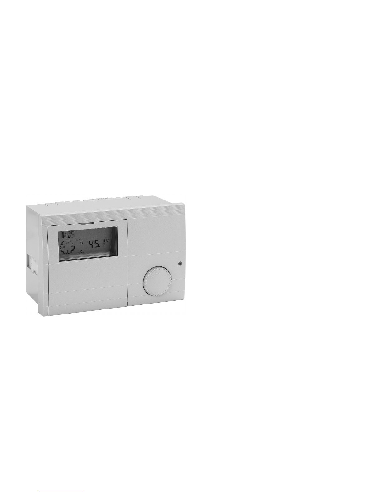
Daikin E8.5064 User manual
Other Daikin Control Unit manuals

Daikin
Daikin BRC1E71 Instruction Manual

Daikin
Daikin RoCon BF User manual

Daikin
Daikin ACZ Manual

Daikin
Daikin BACnet MT3041 Instruction Manual

Daikin
Daikin BRC230Z4 User manual

Daikin
Daikin EKWUFHTA1V3 User manual

Daikin
Daikin EK2CB07CAV3 User manual

Daikin
Daikin E2MV03B6 User manual

Daikin
Daikin Altherma ESBE User manual

Daikin
Daikin BRC1E62 User manual

Daikin
Daikin Myzone 3 Manual

Daikin
Daikin Home Controls EKRMIBEV1V3 User manual

Daikin
Daikin EK2MV2B10C5 User manual

Daikin
Daikin SV1A25AJV1B User manual

Daikin
Daikin Rotex RoCon G1 User manual

Daikin
Daikin EKCB07CAV3 User manual

Daikin
Daikin E2MV107A6 User manual

Daikin
Daikin FWB-CT User manual

Daikin
Daikin IM 837-2 Manual

Daikin
Daikin EKCBX008BBV3 User manual

Popular Control Unit manuals by other brands

Festo
Festo Compact Performance CP-FB6-E Brief description

Elo TouchSystems
Elo TouchSystems DMS-SA19P-EXTME Quick installation guide

JS Automation
JS Automation MPC3034A user manual

JAUDT
JAUDT SW GII 6406 Series Translation of the original operating instructions

Spektrum
Spektrum Air Module System manual

BOC Edwards
BOC Edwards Q Series instruction manual

KHADAS
KHADAS BT Magic quick start

Etherma
Etherma eNEXHO-IL Assembly and operating instructions

PMFoundations
PMFoundations Attenuverter Assembly guide

GEA
GEA VARIVENT Operating instruction

Walther Systemtechnik
Walther Systemtechnik VMS-05 Assembly instructions

Altronix
Altronix LINQ8PD Installation and programming manual