manuals.online logo
Brands
  1. Home
  2. •
  3. Brands
  4. •
  5. Danfoss
  6. •
  7. Thermostat
  8. •
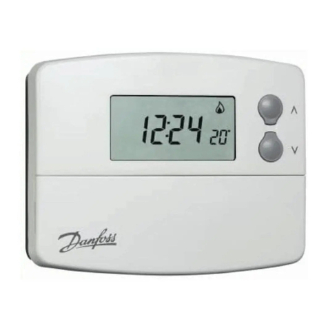
  9. Danfoss TP75 User manual

Danfoss TP75 User manual

1
Installation & Commissioning Guide
Control Features
The TP75 Series of programmable room thermostats incorporate two
special features that can be enabled at the time of installation -
Optimum Start Control and Chrono-proportional Control
Optimum Start Control (OSC)
With this enabled the event 1 control temperature (which would
normally be an increase from an overnight set-back temperature)
may be programmed to be achieved by a desired time. The heating
plant will be switched on earlier than the programmed time by a period
related to the start-up curve selected and the space temperature
sensed at the beginning of the selected start-up period. The diagram
below indicates the switch on periods for the available start-up curves.
If OSC is disabled then the unit will operate as a conventional room
thermostat switching on the heating plant at the event 1 time with the
event 1 temperature being achieved in a time related to the prevailing
conditions.
Battery Compartment Flap lowered
This product complies with the following EC Directives
:
Electro-Magnetic Compatibility Directive.
(EMC) (89\336\EEC), (92\31\EEC)
Low Voltage Directive.
(LVD) (73\23\EEC), (93\68\EEC)
Chrono-proportional Control
Traditional ON/OFF room thermostats control room temperature by
switching the circulating pump and usually the boiler on and off.
Because of the thermal inertia of the heating equipment and the
relatively large switching differentiials of on/off devices large space
temperature variations often occur resulting in poor comfort conditions.
Chrono-proportional Control as implemented in the TP75 overcomes
the problem by ensuring that the boiler fires regularly for periods
calculated to maintain radiator temperature without overheating and
to prevent the radiator temperature falling to a level which can allow
down draughts from cold surfaces e.g. windows to cause discomfort.
The control logic works on a proportional band of 2°C which assumes
that the boiler will operate at full load when the sensed space
temperature is 2°C or more lower than the programmed set point.
The following graph shows the relative on/off periods per cycle against
variances in deviation from the set point.
OFF Time
System Load
0% 25% 50% 75% 100%
0%
25%
50%
75%
100%
100% 75% 50% 25% 0%
Set Temp
-0·5°C
-1·0°C
-1·5°C
-2·0°C
Proportional Band
ON Time
OFF TIME 20 15 10 5 0 min.
ON TIME 0 5 10 15 20 min.
OFF TIME 10 7·5 5 2·5 0 min.
ON TIME 0 2·5 5 7·5 10 min.
3 Cycles / hour
HC75--3
6 Cycles / hour
HC75-C3
Loadcurve
Ï
Desired Event 1
temperature.
Selecting 0
effectively
disables the
OSC function.
Available Start-up Periods
With a -2°C deviation and the 30 min. curve selected the
heating plant will switch on 15 min. before the Event 1 time.
Degrees below the desired
temperature at the beginning
of the Optimum Start Period
120 90 60 30 Event 1
min. min. min. min. time (0)
-1°C
-2°C
-3°C
-4°C
Electronic Programmable Room Thermostats
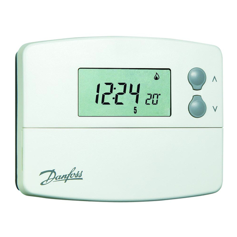
TP75 with integral sensor
TP75 with remote sensor
TP75B with remote teleswitch
TP75 B with remote sensor & teleswitch
Specification
Control temp. range : 5°C to 30°C (41°F to 85°F)
Power Supply : 2 x AA size high quality
alkaline batteries
Switching Action : 1 x SPDT type 1B
Switch Rating : 10 - 250Vac 50/60 Hz 2(1)A
Temperature Accuracy : ± 0.5°C
Time Keeping Accuracy : ± 1 minute/month
Low Battery Warning : 15 days duration
Memory Retention with Batteries Removed : one minute
Enclosure Rating : IP30
Maximum Ambient Temp : 45°C
Designed to Standard : BS EN60730-2-9
Overall Dimensions
Unit : Width: 135mm
Height: 88mm
Depth: 32mm
Remote Sensor : Width: 61mm
Height: 45mm
Depth: 22mm
Pollution Situation : Degree 2
Software Classification : Class A
Rated Impulse Voltage : 2.5 KV
Ball Pressure Test : 75°C
TP75
TP75
2
Fig. 4 Factory pre-set
DIL switch
settings.
7 day
OSC OFF
ON/OFF
Chrono 3
5/2 day
OSC ON
CHRONO
Chrono 6
TP75 Installation
The unit (and remote sensor when used) must be installed by a
competent electrician and the installation should conform to IEE
Wiring Regulations.
The electronics and relay switching circuits are powered by two AA
size alkaline batteries however mains electricity control circuits
connected to this unit should be wired through a full disconnect in
accordance with BS EN60730-1 i.e. one which provides an air gap of
at least 3mm in both poles of the mains e.g. a 13amp plug and
unswitched socket or a switched fused outlet with neon; either fitted
with a 2 amp (max.) fuse.
Fixing
Fig. 2 TP75 or TS2 location
1a. TP75 Select the desired fixing position. (This should
adhere to normal room thermostat practice, see Fig. 2).
1b. TP75A Select the desired fixing position for the TS2
remote sensor. (This should adhere to normal room thermostat
practice, see Fig. 2). Select the desired fixing position for the
TP75A. 1·0mm²solid copper cable should be used to connect
the TP2 to the TP75A. Note that
a) the cable length should not exceed 50 metres,
b) to avoid electrical interference the cable should not be run
parallel in close proximity to other cables carrying mains
electricity, and where necessary the cable should cross
over mains cabling at right angles.
Fig. 3 Wallplate fixing clearances.
2. Whenfixingtheheatingcontrollerwallplatenotethattheterminals
areat the topand the verticalcentre lineofthe heatingcontroller
is at the right hand edge of the terminal 4 recess. Observe the
clearance required for fitting and removal, Fig. 3.
3. Fix the wallplate to the wall or plaster box as required.
4. Makethe wiringconnections forthe systemcontrol circuits,(and
remote sensor when used).
5. Surfacecables canonly enterfrom belowthe unit.If mountedon
aplasterbox cablescanenterfromtherearthroughtheaperture
in the wallplate.
6. These models do not require an earth connection. However, an
earth terminal is provided on the wallplate to ensure earth
continuity for the connections to the heating plant. (A neutral
looping terminal is also provided.)
7. The diagrams on the next page show typical wiring circuit's with
which the units may be used, together with terminal to terminal
wiring information for use with the WB12 Wiring Box included
with Heatshare and Heatplan Control Packs.
8. Clear all dust and debris from the area.
9. Before fixing the unit on to its wallplate, ensure that the four DIL
switches on the rear of the unit (see Fig. 4) have been moved to
the required settings; the choices are:-
Switch No. 1- 5/2 DAY or 7 DAY.
When the switch is in the 7 DAY position each day may be
programmed with different switching times and temperatures.
Placing the switch in the 5/2 DAY position enables Monday to
Friday to be programmed with one set of switching times and
temperatures and Saturday and Sunday to be programmed with
a different set.
Switch No. 2 - OSC ON or OSC OFF
This is used to enable or disable the optimum start control (OSC)
function for event 1. To cater for different types of building
construction with differing fabric constants there are four start-
up curves from which to choose (see the diagram over the
page). These curves dictate how long before event 1 the heating
equipment will be switched on. The selectable start-up durations
are 0:00 0:30 1:00 1:30 or 2:00 (2 hours). (Selecting 0
effectively disables the function).
Once initiated the difference between the space temperature
and the event 1 temperature is used to generate a pre-heat
period proportional to the OSC period selected. The closer the
space temperature is to the event 1 temperature the shorter the
pre-heat period. Refer to the earlier section on Optimum Start
Control for more detail.
It is recommended that the initial setting of the OSC is 30
minutes. See the section on post-commissioning.
Switch No. 3 - CHRONO or ON/OFF
With this switch set to ON/OFF the TP75 will act as a conventional
room thermostat switching the heating plant to maintain the
programmed temperature. When set to CHRONO the control
function selected by switch No. 4 is enabled.
IMPORTANT. For systems with motorised zone valves ON/OFF
mode is recommended.
Switch No. - Chrono 6 or Chrono 3
This switch configures the TP75 to control different forms of
heating system typically as follows:
Use Chrono 3 for high thermal inertia systems e.g. floor
standing cast iron boilers.
Use Chrono 6 for low thermal inertia systems e.g. low water
content boilers and combi. boilers.
See the earlier section on Chrono-proportional Control for more
detail.
10. Position the slots in the top surface of the module over the lugs
atthetopofthewallplate,andhingedownwardsuntilthemodule
is pressed fully against the wallplate. Tighten the two screws
from below to fix the module to the wallplate.
11. Before setting the programmes the unit and circuits should be
checked. Refer to the following Commissioning Instructions.
30mm
minimum
Wall or Plaster bo
mounting holes
Aperture for rear
cable entry
Knockouts for
bottom cable
entry
Outline of unit
Terminals
C/L
N &
looping
terminals
Clearance for
screwdriver
access
3
BROWN
ABC12 3456
BROWNBLUE
ABC123456
N
HPA2
Switched Live to
boiler & pump
control circuit
MAINS
Fused 3 Amp.
TP75
ABC12 3456
N
ZONE CONTROL
BOILER
&
PUMP
N
MAINS
Fused 3 Amp.
N
TP75
ABC1 2 3 456
DIRECT BURNER CONTROL
COMBI BOILER CONTROL
MAINS
Fused 3 Amp.
OUTPUT INPUT
L N
Combi Boiler
Terminals
ABC1 2 3 456
TP75
HEATING SYSTEM CONTROL (HEATSHARE)
NL1234
BOILER
&
PUMP
N
MAINS
Fused 3 Amp.
N
TS15 or TS75 (DHW) TP75 (A)
MAINS
Fused 3 Amp.
N
ORANGE
BROWN/WHITE
GREY
BLUE
HSA3
HEATING SYSTEM CONTROL (HEATPLAN)
MAINS
Fused 3
Amp.
NL1234
TP75 (A)TS15 or TS75 (DHW)
N
GREY N
MAINS
Fused 3 Amp.
HPA2
DHW HPA2
HTG
BLUE
ORANGE
NORANGE
GREY
↑↓
32
1
L
ATC
ATC
32
1
L
BOILER
&
PUMP
NL
Remote Sensor
connections,
if used.
Remote Sensor
connections, if used.
Remote Sensor
connections, if used.
Remote Sensor
connections,
if used.
Remote Sensor
connections,
if used.
TP75
ABC12 3456
N
ZONE CONTROL with ABN-NC A tuator
Remote Sensor
connections,
if used.
N
Switched Live
Output
Live Input
2 port Valve
ABC123456
Live
Input On Off
Heating
ELECTRONICS
INTERNAL WIRING
TYPICAL CONTROL
CIRCUITS
The use of Danfoss Randall Control
Packs with WB12 wiring centre is
recommended.
Cut out terminal to terminal wiring
details for HEATSHARE (HSP) and
HEATPLAN (HPP) PACKS above and
use with the WB12.
Insert for cover of WB12
Wiring Centre. Cut-out and
place over pillars in cover.
$
HEATSHARE SYSTEM
L N
L N
L N
L N
L N
RTS
Remote
Telesw.
if Fitted
TS2
Remote
Sensor
if Fitted
TP75
Remote Devices COM On Off
ABC12 456
28
TS75 or TS15
Off On
NL 1 2 4
69 10 11 11 12 10 5
ATC
COM N/CN/O
CALL SAT
12
12 4 5 6 7 8 9 10 11 12
NL
NL
MAINS
FUSED
A
12
WIRING CONNECTIONS FOR
TP75 WITH A TS75 HSP or TS15 HSP
Heatshare Control Pack
4567
PERM. L
SW. L
N
BOILER
PUMP
IF REQUIRED
BLUE
BRN/WH.
GREY
ORANGE
181012
HEATSHARE
ACTUATOR
IF BOILER DOES NOT HAVE PUMP TERMINALS, CONNECT PUMP
TO 7 (L), 6 (N) & 5 ( ) ON WB12.
TP75B connections A B
TP75AB connections C 1
4
Insert for cover of WB12 Wiring
Centre. Cut-out and place over
pillars in cover.
$
Commissioning
12. Lower the front flap and remove the anti-discharge paper strip
from between the batteries and their contacts, and ensure the
mains power to the control circuit is switched on.
13. Press and release the recessed RESET button to ensure the
factory pre-set programme is active.
14. Establish with the customer the requirements for the operating
mode, and adjust as follows:
Clock type - 24 hour or 12 hour with AM/PM indication.
The factory pre-set is 24 hour. To convert to 12 hour, press
and hold down the NEXT and DAY buttons until the display
changes,thenrelease.(Repeattoreturntoa24hourclock.)
Temperature display - °C or °F
The factory pre-set is °C. To convert to display all
temperatures in °F, press and hold down the DAY and
COPY buttons until the display changes. (Repeat to return
to a °C display.)
15. Check the existing space temperature by pressing and holding
down the two buttons: NEXT and COPY, until the display
changes from time to temperature.
16a. If the set temperature is below the space temperature, use the
sbutton to raise the set temperature. The flame symbol will
appear in the display. Check that the heating plant operates
correctly.
16b. If the set temperature is above the space temperature, use the
tbutton to lower the set temperature below the space
temperature. The flame symbol will disappear. Check that the
heating plant does not operate.
17. These models are supplied with a factory pre-set programme
whichwillbeactiveafteraRESEThasbeenperformed.Thepre-
setprogrammeisshowninthechartwiththeSettingInstructions.
Thechartalsohasspacesforusersowntimesandtemperatures
as required by them.
18. Thetimeandprogrammememoryaremaintainedbythebatteries
which should last more than two years. Every 24 months the
batteries should be renewed. Internal circuitry retains the time
and programme memory for one minute, long enough for the
batteries to be changed.
If the batteries volts drop, before a change is due, a battery
symbol will blink in the display. When this occurs the TP75 will
operate normally for 2 weeks. After the 15th midnight all relays
will switch to OFF, the unit will shut down with just the time
shown. Whennewbatteriesarefittedtheunitwillstarttooperate
normally again.
Advisethe Userto entertheir owntimes andtemperatures inthe
chart on the Setting Instructions.
Post-commissioning
Optimum Start Control
If this has been enabled initially set to the recommended 30 minutes
start-up duration and the event 1 temperature is not achieved by the
event 1 time then refer to the Setting Instructions and increase the
start-up duration one stage i.e. to 1 hour.
If the space temperature at the beginning of an Optimum Start
sequence is consistently lower than the programmed event 1
temperature by more that 4°C then the event 1 temperature may not
be achieved by the event 1 time. In this case the event 1 time should
be brought forward sufficiently to compensate so that the comfort
temperature is achieved when actually required.
Intelligent Anticipator
If when the heating equipment is switched on the room temperature
is 2°C or more lower than the programmed temperature the electronic
anticipation function measures the rate of rise in the sensed temperature
and will switch the heating plant off before the programmed temperature
is reached. The residual heat in the system after the heating plant has
shut down will ensure that the comfort temperature is achieved. This
will improve the comfort conditions and minimise fuel consumption.
Part No. 8958 Iss 8 12/01
Danfoss Randall Limited
Ampthill Road
Bedford, MK42 9ER
Tel: (01234) 364621 Fax: (01234) 219705
Email: [email protected]
Website: www.danfoss-randall.co.uk
DanfossRandallcan acceptnoresponsibilityforpossibleerrorsin catalogues, brochuresandotherprintedmaterial,and reserves theright
to alter its products without notice. This also applies to products already on order provided that such alterations can be made without
subsequent changes being necessary in specifications already agreed.
HEATPLAN SYSTEM
TS2
Remote
Sensor
if Fitted
TP75
Remote Devices COM On Off
ABC12 4 56
29
TS75 or TS15
Off On
NL 1 2 4
610 11 11 12 5
ATC
COM N/CN/O
CALL SAT
12
12 4 5 6 7 8 9 10 11 12
NL
NL
MAINS
FUSED
A
12
WIRING CONNECTIONS FOR
TP75 WITH A TS75 HSP or TS15 HSP
Heatplan Control Pack
4567
PERM. L
SW. L
N
BOILER
PUMP
IF REQUIRED
BLUE
BROWN
GREY
ORANGE
19108
HEATPLAN
ACTUATOR
HTG
IF BOILER DOES NOT HAVE PUMP TERMINALS, CONNECT PUMP TO 7
(L), 6 (N) & 5 ( ) ON WB12.
BLUE
BROWN
GREY
ORANGE
112108
HEATPLAN
ACTUATOR
DHW

This manual suits for next models

3

Other Danfoss Thermostat manuals

Danfoss FH-WT User manual

Danfoss

Danfoss FH-WT User manual

Danfoss ECL Comfort 210 User manual

Danfoss

Danfoss ECL Comfort 210 User manual

Danfoss GET B-RF Guide

Danfoss

Danfoss GET B-RF Guide

Danfoss ECtemp 531 User manual

Danfoss

Danfoss ECtemp 531 User manual

Danfoss RAS-D2 Combi User manual

Danfoss

Danfoss RAS-D2 Combi User manual

Danfoss FH-CWD User manual

Danfoss

Danfoss FH-CWD User manual

Danfoss Type CFR User manual

Danfoss

Danfoss Type CFR User manual

Danfoss FP975 User manual

Danfoss

Danfoss FP975 User manual

Danfoss CF-RF User manual

Danfoss

Danfoss CF-RF User manual

Danfoss 088U0215 User manual

Danfoss

Danfoss 088U0215 User manual

Danfoss TP5001 series User manual

Danfoss

Danfoss TP5001 series User manual

Danfoss REP24 User manual

Danfoss

Danfoss REP24 User manual

Danfoss TRONE-RF User manual

Danfoss

Danfoss TRONE-RF User manual

Danfoss ECL Comfort 210 User manual

Danfoss

Danfoss ECL Comfort 210 User manual

Danfoss CP10C User manual

Danfoss

Danfoss CP10C User manual

Danfoss FMT230D Operating instructions

Danfoss

Danfoss FMT230D Operating instructions

Danfoss KP 61 User manual

Danfoss

Danfoss KP 61 User manual

Danfoss CET2000B-RF User manual

Danfoss

Danfoss CET2000B-RF User manual

Danfoss RT52 User manual

Danfoss

Danfoss RT52 User manual

Danfoss ECL Comfort 210 User manual

Danfoss

Danfoss ECL Comfort 210 User manual

Danfoss RET 230 User manual

Danfoss

Danfoss RET 230 User manual

Danfoss living connect User manual

Danfoss

Danfoss living connect User manual

Danfoss BasicPlus2 WT-T User manual

Danfoss

Danfoss BasicPlus2 WT-T User manual

Danfoss TP7000M User manual

Danfoss

Danfoss TP7000M User manual

Popular Thermostat manuals by other brands

Orbis Thermo X user manual

Orbis

Orbis Thermo X user manual

Seitron hygge home quick guide

Seitron

Seitron hygge home quick guide

Bryant start-up and Installation, Start-Up and Service Instructions

Bryant

Bryant start-up and Installation, Start-Up and Service Instructions

DURASTAR 12B Owners and installation manual

DURASTAR

DURASTAR 12B Owners and installation manual

cor thermostat 5 Advanced Installation and Configuration Instructions

cor thermostat

cor thermostat 5 Advanced Installation and Configuration Instructions

Fiamma OT11 manual

Fiamma

Fiamma OT11 manual

Heatmiser neoUltra manual

Heatmiser

Heatmiser neoUltra manual

Bryant AND THERMIDISTAT CONTROL Homeowner's guide

Bryant

Bryant AND THERMIDISTAT CONTROL Homeowner's guide

American Standard AZON1050AC52ZB manual

American Standard

American Standard AZON1050AC52ZB manual

Comfort Sync A80DS2V Installer's guide

Comfort Sync

Comfort Sync A80DS2V Installer's guide

Hunter 42177 Manual del propietario

Hunter

Hunter 42177 Manual del propietario

White Rodgers 1F95W-80 installation instructions

White Rodgers

White Rodgers 1F95W-80 installation instructions

Elsner KNX eTR 101 Installation and adjustment

Elsner

Elsner KNX eTR 101 Installation and adjustment

Honeywell TH8320WF01 user guide

Honeywell

Honeywell TH8320WF01 user guide

nest Thermostat E installation guide

nest

nest Thermostat E installation guide

Viconics VT7600A installation guide

Viconics

Viconics VT7600A installation guide

Sinope TH1400WF installation guide

Sinope

Sinope TH1400WF installation guide

Regin RCF-230CD user manual

Regin

Regin RCF-230CD user manual

manuals.online logo
manuals.online logoBrands
  • About & Mission
  • Contact us
  • Privacy Policy
  • Terms and Conditions

Copyright 2025 Manuals.Online. All Rights Reserved.