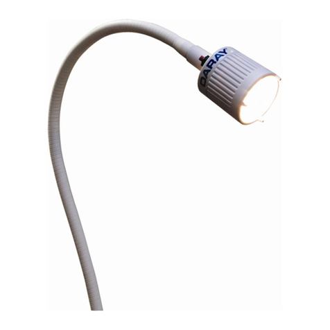
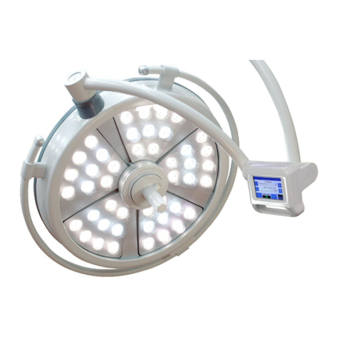
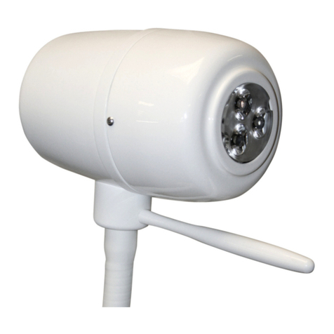
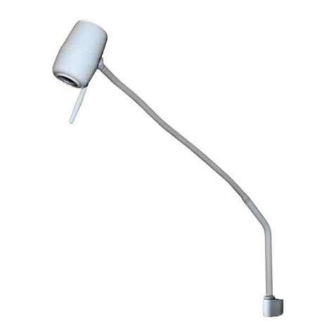
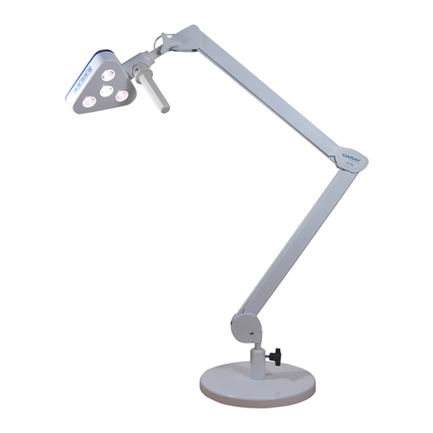
DARAY MAG700 Range User manual

MAG700 Range
LED Magnifier Light
Operating & Installation Manual
QAM.MAG700.0219.5

Page 1 of 19

Page 2 of 19
Table of Contents
1. Introduction ........................................................................... 3
1.1 Supported Lights ................................................................. 4
2. Technical Specifications ............................................................ 5
2.1 Pre-Installation Responsibilities and component packing list ........... 6
2.2 Pre-Start Checks ................................................................. 7
3. Installation ............................................................................ 8
3.1 Considerations................................................................... 8
3.2 Desk version (MAG700LD) ...................................................... 9
3.2.1 Considerations .............................................................. 9
3.2.2 Placement and Installation ............................................... 9
3.3 Wall version (MAG700LW) ..................................................... 10
3.3.1 Considerations ............................................................. 10
3.3.2 Placement and Installation .............................................. 11
3.4 Mobile version (MAG700LM) .................................................. 12
4. Maintenance ......................................................................... 13
4.1 Maintenance schedule ......................................................... 13
4.2 Safety Precautions.............................................................. 13
4.3 Product cleaning & care guidelines ......................................... 14
4.4 Adjustments ..................................................................... 15
4.4.1 Rigid Arm Adjustments ................................................... 15
4.4.2 Detaching Parts............................................................ 15
4.5 Fuses and their replacement ................................................. 15
5. Spare Parts ........................................................................... 16
6. Warranty Information .............................................................. 17
6.1 Returns Policy ................................................................... 17
6.2 Warranty Details ................................................................ 18
Page 3 of 19
1. Introduction
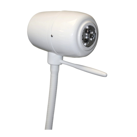
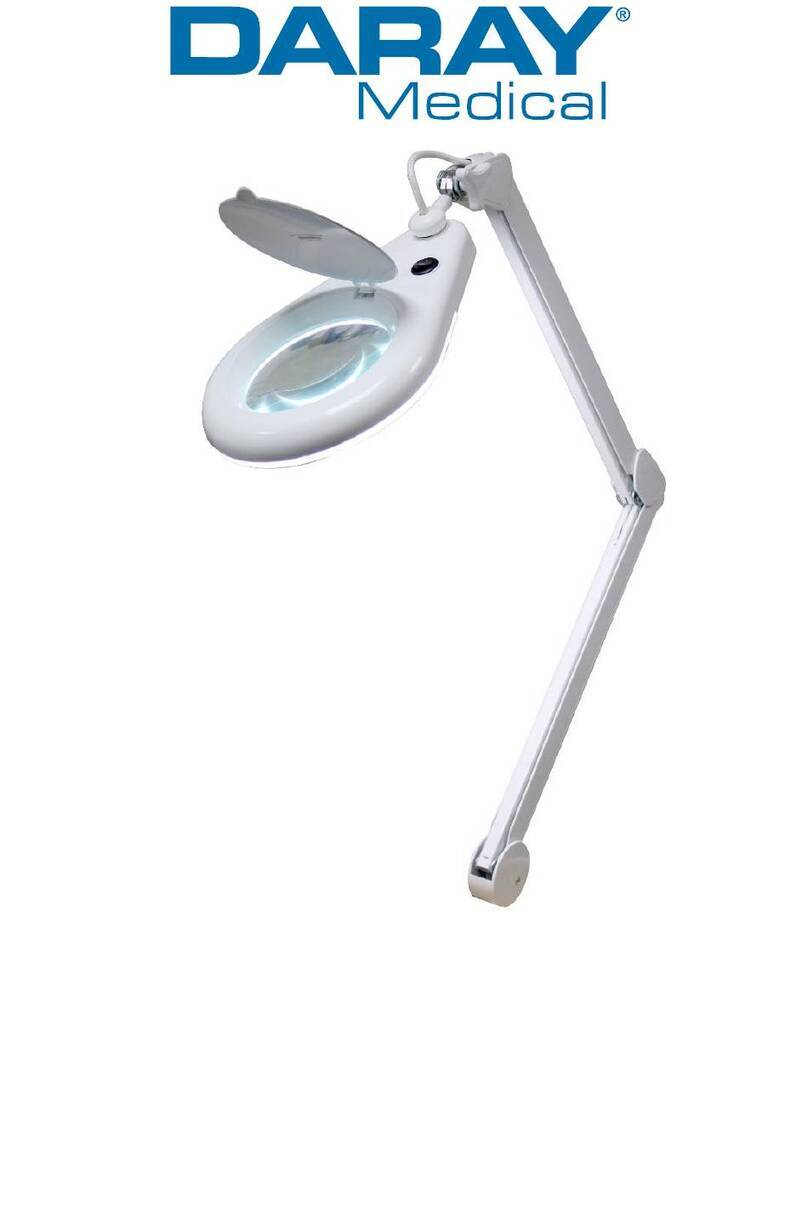
DARAY’s MAG700 Range is a state-of-the art, cost-effective magnifier light for use
during medical or veterinary consultation and diagnosis. The light uses the latest LED
technology to give an intense light at the ideal colour temperature for accurate
medical diagnosis (without the need for secondary filtering) with virtually no heat.
Multiple mounting options are available.
All painted surfaces of the MAG700 Range contain DARAY’s BioProtect™ coating, an
antimicrobial protection against infection-causing bacteria such as MRSA.
The light comprises 4 parts: light-head and rigid arm system, power-supply module
and the mount of choice. The rigid spring-balanced arm allows the light-patch to be
placed accurately and stably where it is needed.
All versions are delivered in special-to-type packaging which identifies on the ends of
the box the model type and serial number of the light within.
This user & installation guide contains all the information you need for installation,
operation and maintenance.
Restrictions and Liabilities
Information in this document is subject to change and does not represent a
commitment by DARAY. Changes made to the information in this document will be
incorporated in new editions of the publication. No responsibility is assumed by
DARAY for the use or reliability of software or equipment that is not supplied by
DARAY.

Page 4 of 19
For further information on our product range and find out more about our Company
please visit www.daray.co.uk or call 0333 321 0971.
This product was designed & manufactured in Great Britain by:
Daray Ltd.
Edison House
Robian Way
Swadlincote
Derbyshire
DE11 9DH
1.1 Supported Lights
The Following Models are supported in this Manual
MAG703LD
MAG703 LED 3-Dioptre Desk Mounted Magnifying Light
MAG703LW
MAG703 LED 3-Diotre Wall Mounted Magnifying Light
MAG703LM
MAG703 LED 3-Dioptre Mobile Magnifying Light
MAG706LD
MAG706 LED 6-Dioptre Desk Mounted Magnifying Light
MAG706LW
MAG706 LED 6-Dioptre Wall Mounted Magnifying Light
MAG706LM
MAG706 LED 6-Dioptre Mobile Magnifying Light
MAG712LD
MAG712 LED 12-Dioptre Desk Mounted Magnifying Light
MAG712LW
MAG712 LED 12-Dioptre Wall Mounted Magnifying Light
MAG712LM
MAG712 LED 12-Dioptre Mobile Magnifying Light

Page 5 of 19
2. Technical Specifications
Light Source
LED
Number of LED’s
80
Average Working Life
>25,000 hours
Light head diameter
200mm
Lens Diameter
125mm
Magnification options
3-Dioptre / 6-Dioptre / 12-Dioptre
Arm Length
800mm reach
Input Voltage
100-240V AC / 50-60Hz
Output Voltage
24V DC 1A
Warranty Period
3 Years (UK only)
NHS E-Class Code
FBU. FKR, KBB
Commodity Code
9018 908400
GDMN Code
12276

Page 6 of 19
2.1 Pre-Installation Responsibilities and component packing list
This document is a guide to the steps that need to be performed to correctly install
the MAG700 Examination light. However, the work required to be performed is the
responsibility of the owner or designated contractor/s.
All fixings between DARAY lights and the building super-structure must be approved
by either the chief project engineer or an appropriate and competent structural
assessor.
The components supplied by DARAY for fitting / installation should be the following
items in the specified quantities.
Desk Clamp
Qty.
Desk Stand
Qty.
MAG703 Magnifier Light (or 706/712)
1
MAG703 Magnifier Light (or 706/712)
1
Desk G Clamp (PIVOTD2)
1
Desk Stand (PIVOTS)
1
User Manual
1
User Manual
1
Fixed Desk Mount
Qty.
Wall Mounted
Qty.
MAG703 Magnifier Light (or 706/712)
1
MAG703 Magnifier Light (or 706/712)
1
Desk Mount (PIVOTFDM)
1
Wall Mount (PIVOTW2)
1
User Manual
1
User Manual
1
Mobile Mounted
Qty.
MAG703 Magnifier Light (or 706/712)
1
Weighted Mobile Mount (MAGMOB)
- Upstand & spigot adapter
- 5 Wheel Castor base
- Balancing weight
- Shakeproof washer
- Securing Bolt
- 5m Orange Power Lead
1
1
1
1
1
1
User Manual
1

Page 7 of 19
2.2 Pre-Start Checks
Please check that the power cable is without visible damage, harsh folds, knots or
cuts in the rubberised coating.
When applicable, please check that the cable is fully inserted into the power socket,
before switching the power on.
Please check that the head and all parts of the base are without visible damage.
2.2 Adjusting the Lighthead
The MAG700 head is secured using a large thumb screw.
This also controls the forward and backward motion of the head itself.
Loosening this thumb screw will allow you to position the lighthead
up or down.
Keep hold of the lighthead when loosening the screw to prevent
sudden drops, care should also be taken not to over tighten
the screw as this could cause stiffness in the joint.
Thumb Screw
Power switch
Dust Cover

Page 8 of 19
3. Installation
3.1 Considerations
Wall Construction
Before fixing it is important to consider the strength of
the wall and the depth of the fixings used.
Use of a building engineer or structural drawings may be
required to decide on suitability.
Examinations to be
undertaken
We recommend the bracket be installed approximately
850-1100mm from the floor to the underside of the
bracket –dependent on couch height.
It may be necessary to adjust this height, if there are
specific medical procedures the light will be used for. If
in doubt consult the end user or DARAY. When installing
the bracket take consideration of where you want the
light head to sit when in its lowest position.
Locations of nearest
mains sockets
The MAG700 wall mounted light uses a plug top
transformer with a DC jack connection.
Only the supplied certified power adapter should be used
with the light.
The length of this cable is approximately 1.5m so the wall
mounted light should be within 1.2m of a mains power
point

Page 9 of 19
3.2 Desk version (MAG700LD)
3.2.1 Considerations
Desk Clamp
This mount can be fixed to desks and workbenches. Before
fixing, it is important to consider the strength and thickness of
the Desk.
Desk Weight
This mount is an unfixed weighted base. It can be positioned
and repositioned as required however please keep in mind that
the weighted base is heavy.
Ensure the weight cannot be accidently knocked off the side of
your work surface as this could cause physical damage.
Fixed Desk
This mount is a long term work surface mounting point.
Before fixing, it is important to consider the strength and
thickness of the work surface; and the suitability of the fixings
used. Use of an experienced fitter may be required.
3.2.2 Placement and Installation
PivotD2
Decide where you want to place the clamp
Slacken the clamp thread underneath to a point where the desk edge can fit between
the clamping sections.
Place and tighten the clamp to lock the mount in position. Once secure, insert the
arm spigot into the mount and supply power to the unit.
PivotS
With a suitable location identified, place the weight onto the desk and insert the arm
spigot, then supply power to the unit.
PivotFDM
With a suitable location identified, use the 4 holes as guides for your fixings. Drill,
screw or install the mount using appropriate fixings.
PivotS
PivotFDM
PivotD2

Page 10 of 19
3.3 Wall version (MAG700LW)
Wall brackets need to be true on all planes.
3.3.1 Considerations
Wall
Construction
Before fixing it is important to consider the strength of the wall
and the depth of the fixings used.
Use of a building engineer or structural drawings may be
required to decide on suitability.
Examinations
to be
undertaken
For correct installation it will be necessary to decide the
location of where you want the head to situate. This will be
dependent on the specific requirements of your work /
examinations, if in doubt consult the end user or DARAY.
Locations of
nearest power
Only the supplied certified power connection should be used
with the light.
The length of this cable is approximately 1.6m so the wall
mounted light should be within 1.3m of a mains power point
Pivot W3 and
W4
Both the Pivot W3 and W4 are primarily designed for hardwired
versions of the light.
The PivotW3 is designed to be compatible with BESA Box style
trunking (please note, reinforcement between the BESA trunking
and the wall structure may be required).
The PivotW4 incorporates a wide spreader plate with an optional
hidden cable feed point.
Use of a competent engineer as well as structural drawings may
be required to decide on suitability.
PivotW2
PivotW3
PivotW4

Page 11 of 19
3.3.2 Placement and Installation
Pivot W2
Place the mounting bracket on the wall in the selected location, bearing in mind
the final position of where the lighthead is required.
Check the alignment of the bracket and ensure that it is level.
Use the bracket as a guide to mark the location of the fixing points on the wall.
Remove the bracket and make holes for the fixings in the desired location.
Attach the bracket to the wall.
Fit the spigot on the end of the arm into the bracket and tighten the locking
screw, do not over-tighten the thumbscrew.
Always loosen the thumbscrew to allow it to turn.
Please note fixings are not included.
Pivot W3
If the unit is being mounted to a BESA junction box, the location of the BESA will
need to be in a pre-determined location so as to ensure that when the light is fitted
where the final location and range of movement of the light allows it to be used
appropriately by the end user.
Ensure the BESA (junction) routing is level and secure to the wall.
Insert the light into the mounting bracket and tighten the thumbscrew to lock
the bracket onto the spigot.
Feed the cable through the silicone tubing and make the electrical connection.
Connect the grounding wire from the back of the bracket to an appropriate
earthing point within the BESA terminal.
Screw the bracket onto the BESA junction box.
Insert the included blanking caps into the unused holes on the front of the
bracket.
Loosen the thumb screw on the side of the unit to allow movement of the light.
Pivot W4
The Pivot W4 is designed with an enlarged spreader plate for use with thinner
mounting areas (such as partition walls) along with hidden hardwiring.
Place the mounting bracket on the wall in the selected location, bearing in mind
the final position of where the lighthead is required.
Ensure the mounting bracket is level and balanced on both planes.
Mark and drill the holes for fixing the bracket to the wall.
Feed the cable through the silicone washer and then the bracket, make the
electrical connection.
Tighten the thumb screw on the side of the unit to lock the light in place.
With the cables fed appropriately, connect the bracket to the wall / panelled
surface.
Loosen the thumb screw on the side of the unit to allow movement of the light.

Page 12 of 19
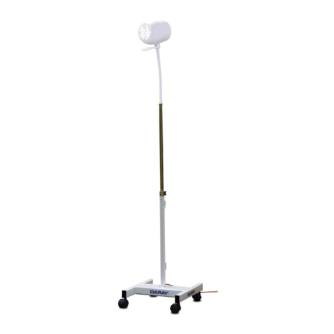
3.4 Mobile version (MAG700LM)
See instructional sheet for mobile base.
Remove the light from its packaging.
Place the castor base on firm ground and insert
the upstand into the hold located in the centre.
Placing hands on the top of the upstand, push
down with a firm pressure until the upstand is
fully inserted.
NOTE: Insertion of upstand may be very tight,
and may require the use of a wooden or rubber
mallet to tap the upstand downward.
Rest the mobile base on its side. Push the bolt
through the washer and weight plate. Align the
bolt with the threaded hole in the bottom of the
upstand, insert bolt and turn in a clockwise
direction until tight.
WARNING: Do NOT over tighten the bolt
Once fitted, the upstand will not be able to be
removed from the castor base.
Insert the light-arm's spigot into the top of the
upstand and tighten the knob to secure it in place.
WARNING: DO NOT LIFT THE LIGHT BY THE
ARM AS THIS CAN CAUSE DAMAGE

Page 13 of 19
4. Maintenance
The proposed maintenance is only a suggestion. Depending on the use of the product
and the operating environment, this may need to be revised more often.
DO NOT ATTEMPT ANY FIXES BEFORE CONSULTING DARAY.
If you cannot resolve a problem then please contact our helpline on 0800 878 9864
4.1 Maintenance schedule
Weekly checks
should include:-
Range of movement testing, it should be light and easy to move
throughout the range
No visible signs of excessive wear.
Monthly checks
to include:-
Check the joints and thumb screws for wear and report as
necessary
Six monthly
checks to
include:-
Remove arm, clean spigot and re-grease as necessary.
Check all electrical connections are sound and that there is no
visible cable wear.
All fixings to be checked and be of sound construction.
4.2 Safety Precautions
For all cleaning work, power off the equipment and where possible unplug
the mains socket, only minimal cleaning fluids should be used.
Please do not look directly into the light source when illuminated.
If the equipment is dented or scratched this should not impact the usability
of our lights however we advise that if the BioProtect® coating is damaged
and the metal casing underneath is visible, please do not attempt to ‘paint’
over it as this will impact upon the effectiveness of the coating, simply use
an alcohol based cleaning spray when cleaning and pay special attention to
the cut.
If there is damage to the power cable or if exposed wire is visible
DO NOT USE

Page 14 of 19
4.3 Product cleaning & care guidelines
The MAG700 Range features BioProtect® antimicrobial coating on all painted surfaces and has a
fully-enclosed head with an Ingress Protection (IP) rating of 54.
These guidelines are provided to help you maintain your equipment properly and prevent any
damage. Use of incompatible cleaning chemicals can adversely affect the finish and physically
damage the metal and plastic parts of the DARAY product, invalidating its warranty.
Please ensure these instructions are passed to the persons responsible for cleaning and they are
followed before each use.
Manufacturers recommended cleaning method:
1. Turn off the power to the light, and where possible, unplug the mains socket.
2. Remove noticeable contamination. Pay special attention to the light head and handle.
3. Ensure the equipment is surface-cleaned and disinfected using an appropriate, non-
abrasive cleaning agent (see recommended list below).
4. Dry all surfaces thoroughly with a clean cloth and check for damaged surfaces,
discolouration and/or contamination.
NOTE: Some DARAY products feature our BioProtect® antimicrobial coating on painted finishes.
This is designed to assist with infection control and is not a replacement for cleaning.
CAUTION: Our products are NOT waterproof. The equipment and accessories (included chargers
and battery packs) MUST NOT at any point be saturated, to prevent water ingress. Use a damp
cloth or saturated wipe if necessary. All electrical safety guidelines should be followed.
Any damage caused as a result of not following these guidelines will void any product warranty.
Below is a partial list of recommended surface agents:
Cavicide™ products
Isopropyl alcohol-based cleaners (<40% alcohol)
Ethyl alcohol-based cleaners (<40% alcohol)
Lysol® disinfectant
Other non-bleach and non-abrasive disinfectants or cleaners
DO NOT USE agents containing the following:
Organic, mineral and oxidizing acids (min. pH value 8.5)
Bases (max. acceptable pH value 8.5)
Oxidation agents (e.g. Hydrogen Peroxide)
Halogens (chlorine, iodine, bromide)
Aromatic/halogenized hydrocarbons
Bleach-based cleaners (e.g. Clorox™, Sterilox™)
Abrasive cleaners (e.g. Comet Cleaner™)
Acetone-based cleaners (e.g. nail polish remover, Goo-off™)
MEK (Methyl Ethyl Ketone)
If you are unsure whether you are using the correct cleaning fluids on your DARAY equipment,
please feel free to get in touch with us for advice.

Page 15 of 19
4.4 Adjustments
4.4.1 Rigid Arm Adjustments
The MAG700 lights are all mounted on spring tensioned rigid arms which are balanced
specifically to be able to be moved using a single finger touch.
Warning! These arms are under spring tension, as such do not try and
adjust the internal mechanics of the arms.
These arms shouldn’t need adjustment in their life cycle however if they start to
droop or require any other work, we recommend that you contact Daray customer
services to discuss this.
4.4.2 Detaching Parts
De-construction of the lights should be done following a reverse order of the
instructions in section 4.
The MAG700 is a completely enclosed light and arm it should not be
opened and is not serviceable outside of a DARAY Authorised service
centre.
For any issues requiring service work on the MAG700 please contact DARAY, as
unauthorised work will invalidate the warranty.
4.5 Fuses and their replacement
The MAG700 series is a mains powered device which has a fuse located in the plug for
the wall socket. There are no other user changeable parts in this light. For any
advice on internal circuit burn-outs and other replacements; please contact Daray.
The fuse supplied in the plug is 3 amps. To replace the fuse you will need a thin flat
bladed screwdriver. Insert the screwdriver into one of the slots in the side of the
fuse housing and wedge the fuse and its housing out of the plug. Replace and
reinsert.
Power on the light and check that it is fully functional. If fuse blows again then it
may need investigating further by an engineer.

Page 16 of 19
5. Spare Parts
Picture
Description
Order Code
Head thumb Screw
CS6143
Wall bracket thumb
screw
D16247
For any SPARE PARTS or TECHNICAL ISSUES phone DARAY’S Service Delivery Team on:
+44 (0) 800 878 9864
Opening times 9am–5pm Monday to Thursday (excluding bank holidays)
9am-2:30pm on Friday
Or email:
support@daray.co.uk
IF THE LIGHT WAS ORIGINALLY PURCHASED THROUGH A DISTRIBUTOR CONTACT THEM IN
THE FIRST INSTANCE FOR A RESOLUTION
Please contact DARAY for help with any problems that the distributor cannot solve.

Page 17 of 19
6. Warranty Information
6.1 Returns Policy
DARAY's standard warranty is 12 months. However, this period may be extended to 3 years* free of
charge by completing and submitting the warranty registration.
For the specific warranty period for this product, please refer to the warranty symbol in the upper right
of this page.
We want you to be completely satisfied with your purchase. If you need to return goods purchased from
DARAY Ltd, please read the following information carefully.
The DARAY Ltd returns policy provides guidance on when you can return goods we have supplied, and what
you can expect from us once you do. To see our detailed returns policy and procedure visit
www.daray.co.uk/returns
TYPE OF RETURN
REMEDY
DAMAGED GOODS
Goods which are physically damaged on delivery
We must be notified within 24 hours of receipt.
Dead On Arrival (DOA)
Goods which do not work
Goods which do not work on arrival or develop a fault
within 28 days, we will advance replace the item.
GOODS DEVELOPING A FAULT
Goods which have developed a fault within the
warranty period.
If the fault develops after 28 days, but within the warranty
period, we will initiate the returns procedure.
NON WARRANTY
Goods which have developed a fault outside the
warranty period.
If a fault develops outside the warranty period, we will
initiate the returns procedure charges may be applicable.
OTHER
Any situation which is not covered by any of the
above.
We will always try to help, but we cannot normally offer a
refund.
For additional clarification, please refer to our terms and conditions at www.daray.co.uk/terms.
In a small number of cases, we may determine that a replacement would not work any better than the
original product we supplied. In such cases we will only offer a refund rather than a replacement for
qualifying returns.
Replacement bulbs and spare parts ordered on our website or from supplied part codes are not eligible
for credit. We will accept returns and exchange for the correct item.
If your purchase an item incorrectly you can return it within 14 days and it can be exchanged for another
product of equal or higher value, excluding transportation charges incurred. Goods and packaging must be
returned in their original condition. Under no circumstances will goods be accepted for return if they are
damaged, have been subjected to improper handling or abuse or have been used.
If you send us goods that do not qualify for return, you will invalidate your claim to any refund, and you
will be obliged to compensate DARAY Ltd for the cost of return postage and any other reasonable costs
incurred processing the goods. Your statutory rights are not affected.
IMPORTANT!
Please fill out your warranty registration online at
www.daray.co.uk/warranty or contact Daray by phone (0800 878 9864)
or email support@daray.co.uk
Year 1: Warranty includes parts and labour
(Return to Base)
Year 2-3: Parts only
*UK only

Page 18 of 19
6.2 Warranty Details
TERMS AND CONDITIONS OF WARRANTY
1. To qualify for this warranty you must register on www.daray.co.uk or return to Daray Ltd (Daray) the duly
completed warranty-registration form accompanying the product.
2. Daray warrants this product (excluding lamp) against faulty material and workmanship during the period of
the warranty. The period of warranty is the period stated on your warranty card and commences on the date
of purchase of the product. In the event that the product is not in good working order Daray will provide,
during the warranty period, a free repair service within the United Kingdom. The warranty is subject to
proof of purchase being provided; therefore, you should retain your original receipt.
2.1 The repair service consists of the provision of spare parts and/or replacement products (at Daray’s
discretion) which will be provided on an exchange basis and will either be new, equivalent to new or
reconditioned. All replaced spare parts and products shall become the property of Daray.
2.2 Daray’s only obligation under this warranty is the provision of the service as set out above.
2.3 All products are returned to Daray at the customer’s cost and risk. Products to be returned should be
adequately packed. For the address to send returns to please visit www.daray.co.uk
3. Daray’s arrangements for providing service provided under this warranty may include the use of sub-
contractors.
4. This warranty does not cover damage or defects in the Product caused by or resulting from:
Wilful neglect or negligence by anyone other than Daray;
Improper use, storage or handling of the product;
Use of non-Daray approved parts (such as replacement lamps) not compatible with the Product;
Fire, accident or disaster;
Use of non-Daray modifications other than in accordance with Daray’s instructions;
Attachment of fittings and accessories not approved by Daray;
Repairs, modifications carried out by service personnel not approved by Daray;
Damage caused by chemical corrosion from cleaning agents not approved by Daray.
Failure to use or install the product in accordance with the manufacturer’s instructions.
5. Nothing in this warranty shall have the effect of restricting or excluding the liability of Daray in respect of:
a) Death and personal injury caused by the negligence of Daray, or for fraud;
b) Under the Consumer Protection Act 1987 to a person who has suffered damage caused by a defective
product or to a dependant or relative of such a person;
c) Direct damage to your property caused by the proven negligence of Daray.
6. This agreement does not give any rights other than those expressly set out above and in particular, Daray will not
be responsible for any loss of income, profits or contracts or any direct or indirect consequential loss, damage
caused to or suffered by the purchaser as a direct result of this agreement.
7. This warranty is offered (subject to these terms and conditions) in addition to, and does not affect your
statutory rights.
8. Daray may disclose your details and other personal information to companies within the Daray group including
any subsidiary company or sub-contractor of Daray for the purposes of performing our obligations hereunder.
9. You must not resell outside the UK any products supplied by Daray and covered by the Export of Goods
(Control) Order 1992 (or any law that replaces it) without obtaining all necessary licences. You also agree
not to sell the product in the UK if you know or think that the person buying the product intends to export
it without getting the necessary licences. You agree to impose similar conditions to these on anyone you sell
the product to.
10. These conditions shall in all respect be governed and construed in accordance with English law and the
exclusive jurisdiction of the English courts.
Product:
Serial No:

Page 19 of 19
Service Notes
Other manuals for MAG700 Range
1
This manual suits for next models
3
Table of contents
Other DARAY Medical Equipment manuals

DARAY
DARAY X200 Manual

DARAY
DARAY X210LED User manual

DARAY
DARAY SL720 User manual

DARAY
DARAY MAGW150 User manual

DARAY
DARAY SL720 User manual

DARAY
DARAY X100LED User manual

DARAY
DARAY V60 User manual

DARAY
DARAY X100 Manual

DARAY
DARAY X230LED User manual

DARAY
DARAY MAG700 Range Installation and operating instructions
Popular Medical Equipment manuals by other brands

Otto Bock
Otto Bock 28R14 Instructions for use

Studex
Studex System 75 Operator's manual

Otto Bock
Otto Bock Terion K2 1C11 Instructions for use

Medela
Medela Thopaz+ Quick reference guide

Coopers of Stortford
Coopers of Stortford 10470 Instructions for use

HeartWare
HeartWare Ventricular Assist System Patient manual