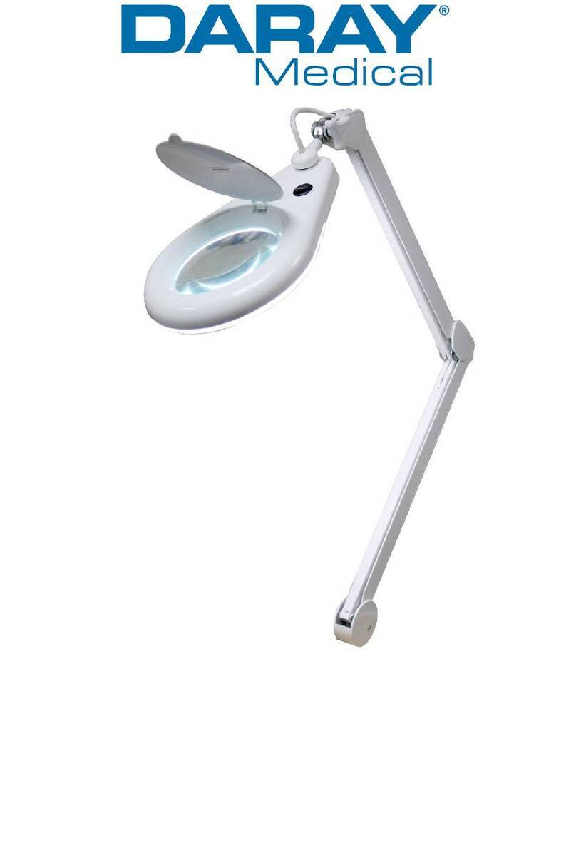
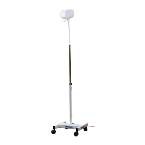
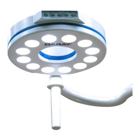
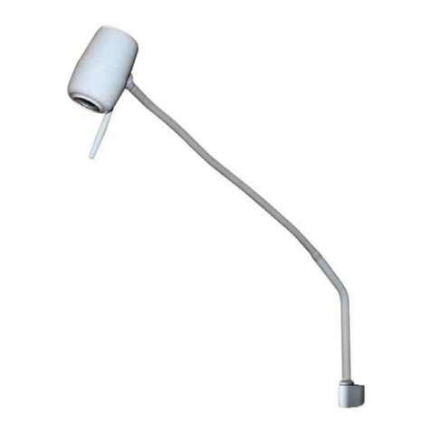
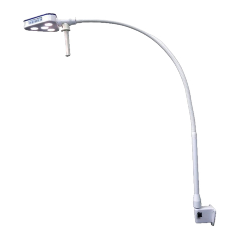
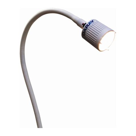
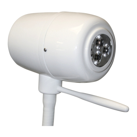
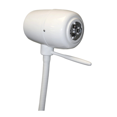
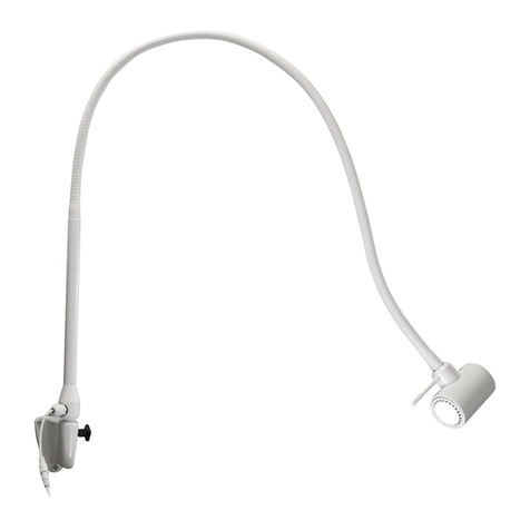
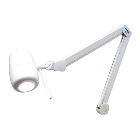
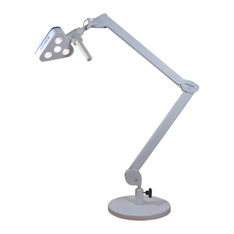
DARAY SL200 Series User manual

SL200
CEILING, WALL AND MOBILE
INSTALLATION AND
OPERATING MANUAL
QAM.SL200.1112.13


3
1.
GENERAL DESCRIPTION
4
2. S
PECIFICATION
4
Serial numbers
and Labelling
4
3.
DIMENSIONS/
RANGE OF MOVEMENT
5
Mobile model
5
Wall
/ceiling
model
(1)
6
Wall/ceiling
model
(2)
7
4.
OPERATION
8
Wall and ceiling models
8
Mobil
e models
8
Batter back
-
up module
9
5
LAMP REPLACEMENT
10
6
FUSE REPLACEMENT (MOBILE ONLY)
11
7
MAINTENANCE
1
2
Cleaning and disinfecting
1
2
Routine maintenance
1
3
Adjustment of arm to prevent drift
1
3
INSTALLATION
/ASSEMBLY
1
4
Installation
-
C
eiling m
ount
14
Installation
-
Wall m
ount
20
Assembl
-
Mobile mount
2
2
Installation
–
Fit the jib
-
joint cover
2
4
Installation
–
Fit the light
-
head
2
5
9
SPARE PARTS
2
6
RETURNS POLICY
2
6
WARRANTY
2
7
Warrant Registration
30
Tel: 0 44 375 9000 Fax: 0333 321 0973
email: info@daray.com url: www.daray.com

4
1. GENERAL DESCRIPTION
The DARAY Illumin8 SL200 is a powerful minor-surger light which is available in wall, ceiling
or mobile versions. The SL200 differs from its predecessor in having variable intensit and a
more robust method of mounting the light-head.
The SL200 is for use during minor procedures, although it is also suitable for diagnosis where
a powerful light of natural da light colour is required. The light uses a sophisticated
reflector to produce a ‘clean’ light-patch with virtuall no heat in the beam. A
pol carbonate diffuser gives good shadow reduction whilst protecting the light-head’s
components. A BioProtect
®
handle is provided. All surfaces are smooth to aid cleaning and
sterilisation.
The SL200C comprises 4 parts: a ceiling mount containing a transformer to convert mains
voltage to a safe low voltage to power the light, a variable intensit controller and a
suspension arm and a light-head.
The SL200W each comprises 4 parts: a wall mounting containing a transformer to convert
mains voltage to a safe low voltage to power the light, a variable intensit controller and a
suspension arm and a light-head.
There are 2 versions of the wall mounted power-suppl module: one for use where the
mains-electrical suppl cables are ‘chased’ into a wall, and the other fitted with an IEC inlet
so the mains ma be supplied via a plug-in flex from a standard mains socket.
The SL200M comprises 3 parts: a base, an up-stand with a control box containing a variable
intensit controller and a transformer to convert mains voltage to a safe low voltage to
power the light, a suspension arm and a light-head assembl .
2. SPECIFICATION
SL200C/SL200W
SL200M
Light output at 1m
0
-
70,000 lux
Col
our temperature
4,000 K, ±5%
Patch diameter at 1m
180mm
Power of lamp
100W
Operating voltage
24V AC
Input voltage
230 V 50 Hz mains, class 1 (earthed)
SL200C/SL200W arm reach
1650mm
825mm
Jib arm vertical movement
+15°,
-
45°
Quality approvals
CE, Me
dical
-
Device Directive 93/42/EEC, EN60601
Serial Numbers and Labelling
Each SL200 is assigned a unique serial number located on the mounting arm, and is also
identified b a label on the arm.
The power-suppl module carries its own identification and serial number.
5
3. DIMENSIONS/RANGE OF MOVEMENT
MOBILE MODEL

6
WALL/CEILING MODEL (1)

7
WALL/CEILING MODEL (2)

8
4. OPERATION
WALL/CEILING MODELS
The SL200 wall and ceiling models are intended to be powered b a switched fused spur.
The fuse should be rated at 5A. Alternativel provide another form of fused isolation.
Installation of the supplied variable intensit controller is optional.
Connect the SL200 to the mains and turn on at switched fused spur.
Where fitted, operate the variable intensit control on the power-suppl module b pushing
the knob.
Turn on the light using the switch on the head mounting. Set the required light intensit b
rotating the intensit control knob.
If the light does not illuminate tr pushing/rotating the intensit control knob. If there is
still no illumination, change the lamp – see Section 4.
Note: Further fault investigation should be undertaken by only a qualified electrician.
Use the handle to steer the light-patch to where ou want it; in the interests of cross-
infection control, avoid touching an other part of the light. The suspension arm swivels at
the mounting and at the joint between the primar and jib arms. The jib arm allows the
light-head to be moved up and down. The light-head itself can rotate 350° on the jib arm,
and be tilted +/- 90° from the horizontal.
After use, isolate the power on the wall, as well as the light-head switch.
MOBILE MODELS
Plug the light into the mains and switch on the mains switch on the front of the PSU. Adjust
the output intensit with the dimmer control on the front of the PSU.
The handle on the light-head should be used to point the light-patch where it is required. The
three castors on the base have brakes which can be used to help keep the base from moving
whilst the light-head position is adjusted.
Alwa s turn the light off at the mains when it will not be used for an significant length of
time.
Warning: Only move the SL200 mobile light using the handle.

9
BATTERY BACK-UP MODULE
The optional batter back-up module restores power if normal
mains power is interrupted or impaired. It also has the advantage
of the addition of a light intensit control.
To operate, turn the power switch (
POWER SW.
) on, turn the lamp
switch (
LAMP SW.
) on and turn the intensit controller from 'OFF'
through 'ON' and adjust to the desired level. If the light is off,
check the on/off switch on the light-head.
If normal mains power is interrupted or impaired the batter back-
up will take over immediatel and will provide power to illuminate
the SL200. When this happens, the batter load indicator (
BATTERY LOAD
) LED will light.
NOTE: There is no intensity control when running on battery power.
When the batter has almost run out of charge, the batter low indicator (
BATTERY LOW
)
LED will light. It is essential that normal mains power is restored at this point to prevent the
loss of illumination.
When the module is connected to the mains with the power switch on, the internal batteries
are continuousl charged whether the lamp is on or off.
Battery low
indicator
Battery
load
indicator
Lamp
switch
Intensity
controller
Power
switch
Catch
Cover screw
Intensity
controller

10
5. LAMP REPLACEMENT
TURN OFF the mains power.
Remove the diffuser b undoing the 4 crosshead screws.
Remove the 'blue' filter. Note: take care when handling the blue borosilicate glass filter.
It is fragile and costly to replace.
Gentl move the lamp shield to one side
The shield can be refitted, if it comes out of its
retaining groove, b squeezing the sides of the wire
holder.
Remove the lamp b moving it from side to side and
pulling it gentl out of its holder.
CAUTION: the lamp may be very hot!
Holding a replacement lamp b its plastic packaging, insert the
wire connectors into the lamp holder.
CAUTION: use only LB4059 replacement lamps from DARAY.
These are special lamps and the use of any other type would
seriously impair the performance of your light.
CAUTION: do not touch the lamp quartz envelope with your
fingers.
Refit the lamp shield, glass filter and the diffuser.
CAUTION: Do not overtighten the screws that secure the blue borosilicate glass filter.
This can cause the material to crack and it is costly to replace.

11
6. FUSE REPLACEMENT
CAUTION: fuses normally blow for a reason. Investigate likely faults before changing fuses.
CAUTION: isolate the unit from the mains before accessing the fuses.
SL200 MOBILE
Both the live and neutral conductors
are fused. The fuses are contained in
a holder which is located on the side
of the control box.
Using a flat-blade screwdriver,
unscrew the caps b pushing and
turning anti-clockwise.
Refit new fuses and screw in the caps
b pushing and turning clockwise.
Do not over-tighten.
BATTERY BACK-UP MODULE
The optional batter back-up module has an internal in-line fuse.
If there is no power output from the batteries, when normal mains power is interrupted, the
internal in-line fuse ma have blown. Because of the risk of electric shock and the risk of
permanent damage to the batter back-up module, this fuse must onl be checked or
replaced b a qualified electrical engineer.
Inside the battery back-up module
In-line fuse

12
7. MAINTENANCE
Cleaning and disinfection.
WARNING: Do not use strong chemical cleaning agents such as ‘Dettox’ to sterilise the
light. Do not use any abrasive materials to clean the light. CAUTION the light is not
waterproof, so do not use excessive cleaning fluid amounts.
Suitabl protect hands. Wipe the light using clean tissue or soft towelling - pa special
attention to the switch areas. Appl to all surfaces a 1% solution of sodium h pochlorite
using a soft cloth. Within 10 minutes, remove the chemical from all surfaces using a damp,
soft cloth. The chemical will cause corrosion of metal parts, if it is not thoroughl removed.
Appl Isopranol to the surfaces – this is an alcohol-based fluid which evaporates without
leaving an residue and can be obtained as an impregnated-cloth applicator.
Note: Do not attempt to remove the light-head steering handle.
Routine maintenance.
The SL200 is designed and manufactured to stringent qualit standards. Observing the
following procedures will help to maintain the light’s optimum performance.
Light-head
Clean all exterior surfaces
As required
Disinfecting and cleaning
directions – see above
Remove diffuser and clean internal
surfaces and reflector surface
As required
Disinfecting and clea
ning
directions – see above
Ceiling mount
Operation
Suggested Intervals
Inspect 6 button head socket screws
for tightness and check that washers
are fitted under head
Six Monthl
Tighten with appropriate
Allen ke .
Check that down post is rigidl
mounted to the ceiling (do not exert
undue force).
Annuall
If an movement found
–
immediatel advise our full
service dealer.
Wall mount
Operation
Suggested Intervals
Check for securit of fixing to wall
Annuall
Investigate an looseness
–
ensure our building
contractor is consulted if
looseness found.

13
Arm
Operation
Suggested
Intervals
On wall
-
mounted units, lift the arm so
its spigot is almost clear of the bush in
the wall-mount plate and re-lubricate
if required.
Six
m
onthl
On ceiling m
ount units, support the arm
and remove the 3 screws retaining the
adaptor into the down-tube. Lower the
arm until the adaptor and ke can be
removed. Slide sleeve up and inspect
for lubrication. Re-lubricate spigot and
sleeve if required. Re-assemble.
Six
m
onthl
Check tightness of all fixing screws
Annuall
Check balance of jib over whole range.
O
ne month
after
installation
and then
annuall .
If unbalanced, follow the
procedure, below. If tendenc is
to fall from full up, insert ke in
capstan hole furthest awa and
with jib full up move capstan b
pulling ke towards ou. Repeat
until no fall at top. Reverse
capstan if rise at bottom of jib
movement.
ADJUSTMENT OF ARM BALANCE TO ELIMINATE DRIFT
Insert a small implement (e.g. hex wrench 2mm AF)
into one of the holes and turn capstan in the
direction of Arrow A until desired balance is
obtained.
Note: To eliminate rise in the jib at the full down
position turn the capstan in the opposite direction to
Arrow A.
To assist in making this adjustment, it ma be
necessar to remove the arm joint cover: Remove the
2 snap in plugs and the 2 screws, allowing the cover
half mouldings to be separated and the moving cover
to slide down the jib arm. This provides better access
to the slot through which the capstan nut is adjusted.
Note: When re-assembling, ensure that the moving
cover is correctly positioned with the ‘T’ notation
on the component at the ‘Top’.
Holes
A

14
. INSTALLATION/ASSEMBLY
CAUTION: this product must be earthed.
Installation - Ceiling Mount
Check ou have the following items:
Ceiling
-
mount plate assembl and cover
Down
-
tube
Kit of fittings D10522
Limited
-
rotation device D10524
Light
-
head
and
suspension arm
Power suppl module
Determine where to mount light:
Determine where to mount light from the positioning and ceiling-load forces
diagrams, below:
WARNING: please note that this information is provided for guidance only and that a
qualified builder or structural engineer should be consulted if you have any doubt about
the suitability of the proposed mounting position.
WARNING: the light-head operates from a low-voltage supply produced by a transformer
in the ceiling mount assembly and fed through the suspension arm. On NO ACCOUNT
should the arm be connected directly to mains voltages.

15
Fitting the ceiling plate
Remove the clamp bolts, safet bolt/n lon insert nut and the clamp. Keep these
parts in a safe place for use later.
Fix the plate to the ceiling with bolts, screws or studs and nuts through the centre of each
jack bolt. Do not full tighten the fasteners at this point.
Note: The nuts thread-locked to the upper end of the 3 jack bolts act as pressure pads.
These pressure pads must be seated firmly against the mounting surface.
The jack bolts can then be used to adjust the position of the ceiling plate and down-
tube.

16
Fitting the Down-tube
A 1 metre length of down-tube is included with all ceiling mount kits, and must be securel
fitted in accordance with these instructions.
The down-tube should be cut to length on-site to suit the particular ceiling height and
application.
Note when installed the down-tube must leave clearance above the ceiling mount plate to
prevent the cable being trapped.
For determining the cut point, we suggest measuring the distance between the ceiling
mounting plate, and a point about 1900mm above the floor.
The length of the down-tube should be altered to suit the room dimensions and the
particular application for which the light is to be used.
De-burr as necessary.
NOTE: For suspended ceilings, the ceiling hole trim and retaining band should be placed
over the downtube BEFORE proceeding.
Loosel refit the clamp and clamp
bolts. Fit the down-tube in the clamp
and tighten the clamp bolts to firml
hold it in place. Drill a 6mm hole
completel through the tube via the
guide holes in the clamp and fit the
safet bolt and n lon insert lock nut
supplied.
NOTE: TO ENSURE THE USER'S
SAFETY, THE SAFETY BOLT AND
NYLON INSERT LOCK NUT MUST BE
FITTED PROPERLY
Feed the end of the low-voltage
cable assembl through the tube.
Tighten both clamp screws full and evenl until the tube is firml clamped.
Adjust the 3 large bolts such that the down-tube is absolutel vertical. Tighten the fixing
bolts or screws to firml clamp the jack bolts tight against the joist, tighten the thin
locknuts and re-check that the down-tube remains vertical, and the mounting plate has no
movement. If necessar , repeat the adjustment.
Run the low-voltage cable to the mounted power-suppl module, feed it through the
grommet on the top of the module and connect it to the 2-wa terminal block wired to the
low-voltage output from the transformer.
Refit the module to its mounted rear plate.
NOTE: For suspended ceilings cut a clearance hole in a ceiling tile, replace the tile and
slide the trim up the downtube until it is firml against ceiling tile, then roll the trim
retaining band upward until it holds the trim in position.

17
NOTE: For conventional ceilings fit the cover, holding it in place with the retaining band
from the fitting kit.
Install the primary arm
To ensure the smooth rotation of the arm, it is essential that the primar arm spigot is
lightly lubricated before assembl .
A sachet of silicon grease is provided.
Place the n lon washer over the primar arm spigot.
Insert the primar arm spigot into the down-tube.
Down-tube
Arm assembl
N lon washer
Connector
Primar arm spigot
Down-tube
Suspended ceiling trim
Trim retaining band

18
Join the connector from the primar arm to the connector from the down-tube.
Fit the supplied bungs.
Make sure to sit the joined connectors inside the bung before fitting to prevent the
cable from being damaged.
Fit the jib-joint cover (see p.22).
Fit the light-head (see p.23).
Check ever thing for tightness and safet .
Check the arm and head for freedom of movement.
Rebalance the jib arm if necessar (see p.11).

19
Wiring the SL200C
SL200C wiring diagram
The variable intensit control module should be mounted on a wall at a convenient position
for the user.
Provide a suitable, earthed electrical suppl to the variable intensit control module via a
switched, fused spur.
Run a 1.5mm
2
twin and earth cable to the ceiling plate 230V terminal block.

20
Installation - Wall Mount
Check ou have the following items:
Wall
-
mount plate
Light
-
head
on suspension arm
Power suppl module
To prevent damage in transit, the arm assembl is packed
and delivered with the spigot in the ceiling-mount
configuration.
For wall mounting, turn the primar arm through 180
degrees, as follows:
•Place the arm on a non-scratch surface – remove the 2
screws as shown.
•Turn the primar arm through 180 and refit the 2 screws
tightl , ensuring the cable is not trapped.
Determine where to mount the
light bearing in mind the
following wall-load forces
diagram:
The top of the bracket into
which the primar arm fits
should be 1696 mm above the
floor
WARNING consult a building
engineer, if in doubt.
Secure the plate to the wall,
ensuring that it is trul vertical.
To ensure the smooth rotation
of the arm, lightl grease the
spigot on the primar arm.
WARNING: the light-head
operates from a low-voltage
supply produced by a
transformer in the power-
supply module and fed
through the suspension arm.
On NO ACCOUNT should the
arm be connected directly to
mains electricity.
180°
This manual suits for next models
3
Table of contents
Other DARAY Medical Equipment manuals
Popular Medical Equipment manuals by other brands

Etac
Etac Immedia E-Board Oval Series Instructions for use

Hillrom
Hillrom A-20500 Instructions for use

Smith & Nephew
Smith & Nephew RENASYS EDGE Quick reference guide

Cooper Surgical
Cooper Surgical frigitronics CE-2000 Instructions for use

Cooper Surgical
Cooper Surgical LEEP PRECISION LP-10-120 operating manual

Contec
Contec CMS-50f user manual

Atos
Atos Provox LaryTube When and How to Use

B. Braun
B. Braun Aesculap Neurosurgery Instructions for use/Technical description

Breas Medical
Breas Medical PV 10 Clinician manual

Hillrom
Hillrom Extended Care Solution quick reference

Inogen
Inogen One G4 Getting started guide

Ossur
Ossur OAsys Carticare Instructions for use