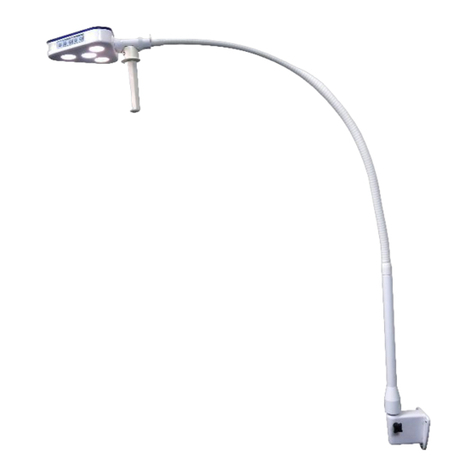
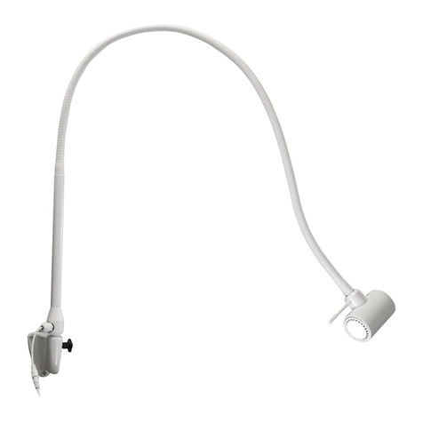
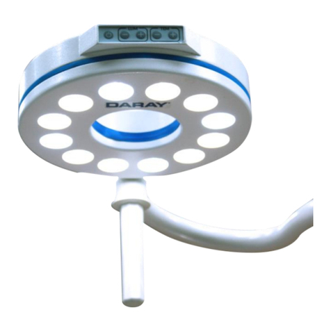
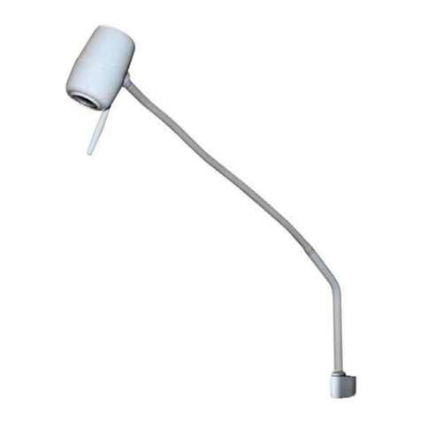
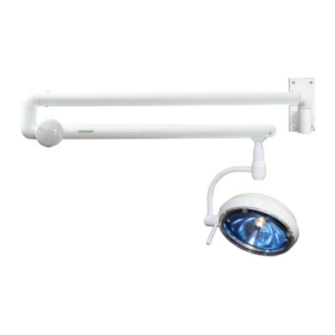
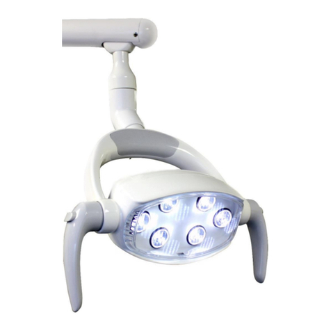
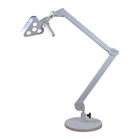
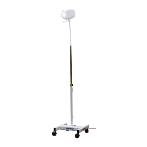
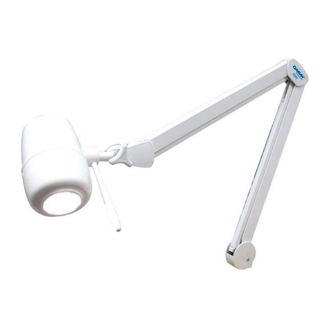
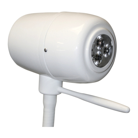
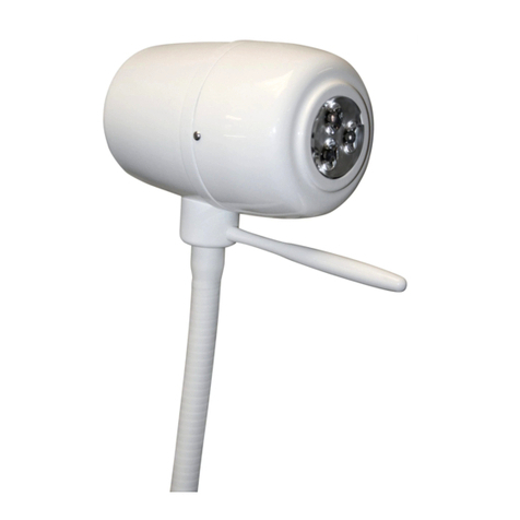
DARAY SL700 Series User manual

SL700 Series
LED Operating Theatre Light System
Including optional SL / camera
Operating & Installation Manual
QAM.SL700L.0219.10

Page 1of 39

Page 2of 39
Contents
1. Introduction .................................................................3
1.1 Supported Lights........................................................3
1.2 Lighting Specification..................................................4
1.3 Pre-Installation Responsibilities and component packing list....4
1.4 Packing List .............................................................4
1.5 Essential adjustment information....................................6
2. Operation Guide Section ..................................................7
2.1 Range of Motion ........................................................8
2.2 Pre-Start Checks........................................................9
2.3 Battery Back-up ........................................................9
2.4 Powering On & Variable Intensity....................................9
2.5 Adjusting the Lighthead ............................................. 10
2.6 The SL7 Camera ...................................................... 11
2.7 How to operate the Monitor and Camera Attachments ......... 12
3. Installation Guide Section............................................... 13
3.1 Considerations ........................................................ 14
3.2 Ceiling Mounted Lights .............................................. 15
3.2.1 Attachment methods and void suspension ..................... 15
3.3 Lighting configuration ............................................... 15
3.3.1 Affixing the Ceiling plate ......................................... 15
3.3.2 Wiring and transformer layout ................................... 16
3.3.3 Fixing the arms and main installation .......................... 18
3.3.4 Mounting the Monitor Bracket.................................... 20
3.3.5 Lighthead Attachment ............................................ 21
3.3.6 Lights with Camera’s and monitor displays .................... 23
3.3.7 Attaching the Camera ............................................. 24
3.3.8 Attaching the Ceiling Cover ...................................... 25
3.4 Wall Mounted Bracket Assembly ................................... 26
3.4.1 Considerations...................................................... 26
3.4.2 Placement and Installation ....................................... 27
3.5 Mobile Mount Assembly.............................................. 30
4. Maintenance............................................................... 33
4.1 Maintenance schedule ............................................... 33
4.2 Safety Precautions ................................................... 33
4.3 Fuses and their replacement ....................................... 33
4.4 Product cleaning & care guidelines................................ 34
4.5 Adjustments........................................................... 35
4.5.1 Ceiling and Wall Mounted Adjustments ......................... 35
4.5.2 Mobile Adjustments................................................ 36
4.5.3 Replacing the LED Bulbs .......................................... 36
5. Troubleshooting Guide................................................... 37
6. Camera & Monitor Troubleshooting Guide ............................ 38
7. Replacement Parts ....................................................... 38
8. Warranty Information .................................................... 39
8.1 Returns Policy......................................................... 39
8.2 Warranty Details...................................................... 40
Page 3of 39
1. Introduction
Thank you for choosing a Daray SL700 Series Operating Theatre Light.
The SL700 Series of lights are specifically designed to meet the demanding needs of today’s medical department
whilst providing the finest quality design with superior performance, reliability and value. This manual has been
provided to give detailed descriptions covering the performance, operation and safety information of the device.
It’s recommended that users read through this manual before using the device so they are aware of how to operate
the device and all of its features appropriately.
This user & installation guide contains all the information you need for installation, operation and maintenance of
the lights and additional camera option.
Restrictions and Liabilities
Information in this document is subject to change and does not represent a commitment by DARAY. Changes made
to the information in this document will be incorporated in new editions of the publication. No responsibility is
assumed by DARAY for the use or reliability of software or equipment that is not supplied by DARAY
For further information on our product range and find out more about our company please visit www.daray.co.uk or
call 0333 321 0971
This product was designed & manufactured in Great Britain by:
Daray Ltd.
Edison House
Robian Way
Swadlincote
Derbyshire
DE11 9DH
1.1 Supported Lights
The Following Models are supported in this Manual
Sl750
Ceiling Mounted
Wall Mounted
Mobile Mounted
SL770
Ceiling Mounted
Wall Mounted
SL750 / 770
Double Ceiling Mounted
SL750 / 750
Double Ceiling Mounted
SL770 / 770
Double Ceiling Mounted

Page 4of 39
1.2 Lighting Specification
1.3 Pre-Installation Responsibilities and component packing list
This document is a guide to the steps that need to be performed to correctly install the SL700 Series Operating Theatre Light
System. However, the work required to be performed is the responsibility of the owner or designated contractor/s.
All fixings between Daray lights and the building super-structure must be approved by either the chief project engineer or an
appropriate and competent structural assessor.
The components supplied by Daray for fitting / installation should be the following items in the specified quantities.
1.4 Packing List (what you should have per lighthead).
SL700 Series Dual Mounted Ceiling Light with camera and monitor
1 Primary Lighthead
1 Secondary Lighthead (satellite)
1 Fixing Plate
1 Ceiling plate with triple arm downtube, pre-wired transformers and a central chock block
1 HD Camera
3 Primary Rotation Arms (pre-assembled with 2 pre-attached suspension arms)
1 loose Suspension arm
2 digital touch screens (pre-attached to each lighthead)
2 Ceiling Mount Cover Halves + 1 securing ring for the ceiling cover
1 monitor mounting arm with bracket
1 Touch Screen Monitor
1 Bag of inter-arm fixings and spare connectors
(Optional Battery back-up, 1 per arm)
1 Autoclavable handle (2 for lights without camera’s)
SL770/SL770LED
SL750/SL770LED
SL770LED
SL750LED
Luminance Lx
40,000~160,000
30,000~160,000
40,000~160,000
30,000~120,000
Colour Temp
3,600~5,500
CRI
Up to 95
R9
90
R13
93
Spot diameter
(d50) mm
120
120
120
120
Spot diameter
(d10) mm
240
240
240
240
Focusing depth
mm
1000
1000
1000
1000
Irradiancy
L400nm W/m2
400nm≤0.002
002≤0.002
400nm≤0.002
002≤0.002
Number of LEDs
120
105
60
45
Focusing
Manual/Electric
LED power W
1 W/pc x 60pcs
1 W/pc x 45pcs
1 W/pc x 60pcs
1 W/pc x 45pcs
Power supply
220V 50Hz
Input power
300W
Average service
life
50,000 hours
SL770 Ceiling Mounted Light
SL750 Ceiling Mounted Light
1 Primary Lighthead
1 Primary Lighthead
1 Fixing Plate
1 Fixing Plate
1 Ceiling plate with pedestal
1 Primary Rotation Arm
1 Suspension Arm
1 Suspension Arm
1 Digital Touch Screen (pre-attached to each
lighthead and a third arm section)
1 Digital Touch Screen (pre-attached to each
lighthead on a third arm section)
2 Ceiling Mount Cover Halves + 1 securing ring
for the ceiling cover
2 Ceiling Mount Cover Halves + 1 securing ring
for the ceiling cover
(Optional Battery back-up, 1 per head)

Page 5of 39
SL750 Mobile Mounted Pack List
Lighthead
Mobile Base with 4 caster lockable wheels
Lower vertical tubing
Upper vertical tubing
Suspension Arm
IEC Power Lead
SL750 Wall Mounted Pack List
1 Primary Lighthead
1 Wall Mount Bracket with pre-attached
transformer and rotation arm
1 Suspension Arm
1 Wall Mount Cover
SL770 Wall Mounted Pack List
1 Primary Lighthead
1 Wall Mount Bracket with pre-attached
transformer and rotation arm
1 Suspension Arm
1 Wall Mount Cover
The ceiling mounted edition of the SL700 series lights has a recommended fixing point of 3 metres from the floor; the minimum
height is 2.7m and maximum of 3.3m. Anything over this height or systems using multiple satellites, will require a customised
length of downtube.
Please contact Daray for further information.
Standard installation height:
3m
Safety type:
Kind I, type B
Working as:
Continuous operation
Temperature:
10℃—30℃
Relative humidity:
10%—80%
Power supply:
220V AC ±10%
Frequency:
50Hz±1%

Page 6of 39
1.5 Essential adjustment information
PLEASE NOTE: THE SUSPENSION ARM IS SENT OUT IN A LOCKED HEIGHT POSITION
For a detailed description of all these adjustments, please refer to page 34 of this user manual.
Rotation arm
Rotation arms are adjusted using tension points located on
the central arm boss.
There are two brakes, one on each side of the unit; When
adjusting this tension ensure you use equal braking on each
side as favouring one side could cause damage.
Suspension arm
Horizontal drift (sideways) is controlled by a pair of Hex
screws on the front side of the spigot joint that connects the
rotation and suspension arms.
Vertical drift (up/down) is controlled by a tension
adjustment located in a keyhole slot under the same spigot
joint mentioned for the horizontal drift
Suspension Arm height
PLEASE NOTE: THE SUSPENSION ARM HEIGHT IS SENT LOCKED
The height of the arm is adjusted using a keyhole hex point
in the end of the arm where it connects to the lighthead
arm.
Once the light is fully installed, insert a hex tool into this
hole to adjust the arms range of movement / upper height.
Lighthead hinge arm
The lighthead’s are on a separate arm section, movement of
this arm is adjusted via the central grub screw located on the
hinge behind the control panel on the arm, this should be
adjusted using a hex tool.
Note: only adjust the central grub screw, the outer two
are tied to the assembly of the arm
Lighthead turning
lighthead itself has one final tension point, this is located at
the base of the head where it attaches to the tertiary arm
system, and this can be seen pictured below
Wall mounted arm adjustments
Wall mounted systems use the same arm design as the ceiling
mounted version.
The main difference in arm configuration for the wall system
is the suspension arm/tertiary arm tensions point. This joint
is controlled via a grub screw mechanic located underneath
the joint.
Mobile arm adjustments
Mobile edition has no Horizontal drift adjustment as the arm
is in a fixed location of a mobile base.
Vertical drift is controlled in the same keyhole slot
mentioned above
Suspension / Tertiary arm tension point is the same as the
wall mounted edition; it is controlled via a grub screw
mechanic located underneath the joint.
Tension grub
screws
tension points
Vertical Tension
Adjustment

Page 7of 39
2. Operation Guide Section

Page 8of 39
2.1 Range of Motion
The full range of motion between the SL700 series varies dependent on mounting.
This is an image depicting the range of motion on a double ceiling mount fitting.
Lighthead
Ceiling Cover over
the ceiling plate
Downtube
Primary Rotation Arm
Secondary Rotation Arm
Suspension Arm
Autoclavable
Handle or
Camera
Control Panel

Page 9of 39
Power
On/Off
2.2 Pre-Start Checks
Please check (when applicable) that the head and arms are without visible damage, and all LED’s are present in the
head.
Please note, the SL700 series may take a few seconds to power on fully and illuminate, please be patient when first
turning on the light.
Users should not look directly into the light as it is bright and will illuminate when powering on.
Please check (when using the mobile version) that the power cable is without visible damage, harsh folds, knots or cuts
in the rubberised coating.
If you are using a mobile version; check that the cable is fully connected to the device and that the plug is fully inserted into
the power socket, when switching the power on.
2.3 Battery Back-up
The SL700 series has the capability of using a battery back-up system.
The battery should be conditioned before being used for the first time. Battery conditioning involves removing all the charge
from the battery. Batteries should be conditioned regularly. Condition a battery when the device is stored for long periods, or
when the charge becomes noticeably shorter.
Follow the steps below to condition a battery:
1. Disconnect the battery from the light.
2. Attach the battery in need of conditioning to a suitable electrical supply.
3. Charge the device uninterrupted for up to 10 hours.
4. Disconnect the electrical supply and re-attach the battery to the light, allow the light (while disconnected from its
primary power source) to run on the battery until it shuts off.
5. Charge the battery until fully charged again.
6. The battery is now conditioned.
Batteries can deteriorate over time, meaning a reduction in their performance.
To check the performance of a battery, follow the steps below:
1. Charge the battery uninterrupted for 10 hours.
2. Disconnect the mains supply to the light and allow it to run on the battery until it shuts off.
3. The operating time of the light reflects the condition of the battery. Replace the battery if the operating time is
significantly lower than the specified time.
2.4 Powering On & Variable Intensity
The SL700 Series uses a microcomputer digital system to control the lighting options of the lights; this system has 10 continuous
steps to adjust light intensity, luminance and colour temperature from on-board memory through a control panel located on the
arm of the lighthead.
NOTE: An icon ∆is displayed when an LED needs to be replaced, if / when this occurs, please contact DARAY.
Ensure mains power is connected to the light and tap the touch screen display; this should then illuminate and display the
controls. Press the green button on the display marked with I and O. The light should then illuminate.
Light Patch Control
Variable Intensity
Variable Colour
Temperature

Page 10 of 39
Use the controls on the display to increase or decrease light intensity (luminance), colour temperature (colour temperature) and
the size of the light patch (light spot).
To power off the light after use, press the green button on the display marked with I and O again. The display will remain on for
a short period, then enter a sleep mode, tap the screen to exit the sleep mode.
Please Note, if the light is turned off at a dimmed level, it will remember that level the next time it is turned on,
please check the luminance level shown on the control pad.
2.5 Adjusting the Lighthead
The SL700 Series lights are secured using a large white, spring balanced and adjustable arm. The head itself has forward and
backward motion through the hinge joint connecting the head to the tertiary arm.
The head can be adjusted through use of the rails, located on the side or by the cone in the centre of the head (which can also
be used to control the light patch size / focusing depth except when this has been replaced with a camera).
Care should be taken not to violently or forcibly adjust the head as this may damage the light.
Lighthead
(Tertiary) Arm
Lighthead Side
Rail

Page 11 of 39
2.6 The SL7 Camera
For the SL700 Series there is an option to have a camera attachment, this would typically be located on the primary surgical
lighthead.
The camera is a 1080P HD digital camera pre-set for auto-focusing and displays real time footage on a 19” TFT-LCD touch screen
display.
This display is mounted on an independent satellite arm in the central suspension, connected through a BNC coaxial cable.
This screen also has built in memory storage to record and “snapshot” footage displayed from the camera. The user also has the
capability to access the local hard disc to edit any recorded video data and transfer it to other systems via USB.
Camera Features:
1.8v FPGA processor with a 2 GB p/s Transmission Rate
20x Optical Enlargement
3.3 Mega Pixel Quality
Image Sensor: 1/2.8 CMOS
Adopts Sony VISCA and PELCO Protocols
Horizontal Resolution: 1080p / 1080i
F = 1.6-3.5, f3.5-85
Horizontal viewing angle: 3.5 –55.4
View Angle (H/V): 160/160
Minimum Object Distance: 5mm
Dot pitch (H*V): 0.297*0.297
Contrast Ratio: 800:01:00
Video Signal Output: HD-SDI, YUV, HDMI, DVI
Minimum Illumination: 0.04 Lux / ICR
SNR: 50db
Operating Temperature: 0-40℃
Response Time: <8ms
Digital Input: SDI
Power Input: 12v DC
Screen Display Features:
Screen: 19 inch TFT-LCD touch screen
Resolution ratio: 1024 x 768
Brightness: 350ccd/m2
Contrast ratio: 800:1
True colour: 262K
MTBF: 50,000 hours
Viewing Angle (H/V): 140/120
Material: High intensity aluminium magnesium alloy.
Input: 12V/5A
Ingress Protection: IP65 (waterproofing grade)
Supports USB
High-precision, touch screen (resistance-type)

Page 12 of 39
2.7 How to operate the Monitor and Camera Attachments
The camera has a 5 button control panel on the side. These buttons are used to control the magnification and focusing of the
lens.
The left and right controls are used to zoom while the up/down controls are used to focus.
Once the installation is complete and the device powers on, the display should directly load into the camera software. This
software has a control panel down the right hand side of the screen which can be removed by pressing the 5th button labelled
FullScreen. To get the panel back you will need to double tap the screen.
The control panel lists 7 options:
Start Recording will start a video recording immediately that is then saved in an MP4 format. This is then saved into the videos
sub-folder located by pressing the open folder button. Snapshotting has the same procedure and images taken can be found in
another subfolder shown by pressing the Open Folder button.
The Monitor itself is defaulted to HD video recording and snapshotting. The hard drive within the monitor is 500Gb and allows
many hours of video recording storage without a problem.
To remove or modify footage there are USB connections located at the bottom of the monitor. The display can be used in a
similar method to a desktop computer.
To use the right click mouse option, you will need to double tap the screen.
If you press Exit or accidently drop out of the software you will have a red Daray background.
To re-enter the software click on the shortcut to Video Recorder, listed on the side of the display.
If this does not resolve the issue, please turn the monitor off and on again.
Please Note, if a USB drive is left in the USB ports the device will not power on.
Start Recording
Snapshot
Open Folder
Setting
FullScreen
About
Exit
Zoom
Focus

Page 13 of 39
3. Installation Guide Section

Page 14 of 39
3.1 Considerations
The ceiling structure must be capable of handling up to a 500kg load.
The procedures below are detailed to a high level however If in doubt please consult a qualified electrician.
Minimum Room Requirements
The SL700 Series ceiling mounted light (single
and double) has a standard fixing height of
3.0m. The design works off a fixed plate
system and has a large vertical motion with a
minimum fixing point of 2.7m.
Maximum Room Requirements
Please note, if the ceiling / fixing point of the
light is above 3.3m then a customised ceiling
mount will be required, (please contact Daray
for more information).
If a suspended ceiling is in the room, you may
be able to construct a platform or suitable
rigging to lower the ceiling plate’s fixing point
to the required height, please note it is
recommended to lower the fixing point to the
same height as the suspended ceiling.
Live Electric Circuitry
All personnel working around live circuitry
should be qualified and following proper
procedures.
Heavy or Difficult fittings
Fitting the ceiling plate can be difficult and
aspects of the fitting may require more than
one person; this work should only be attempted
by appropriate and competent personnel.
Existing Environmental Factors
When fitting, considerations have to be taken
for existing services such as; fire alarms, vents,
lights, etc. along with interior ceiling
construction and any surrounding hazard.
Environmental Responsibility
Once our products are installed all packaging
should be disposed of appropriately and
recycled where appropriate and in accordance
with local governing regulations.
The normal life span of the SL700 series is ten
years. We recommend the equipment should be
discarded and recycled when reaching the end
of its life.
These instructions are based on the assumption of a fresh fit into a room with no previous lighting structures. With installations
onto sites with equipment already in place, we recommend that the previous lights’ mounting plates be removed and the new
ones fitted as if into a fresh fitting.

Page 15 of 39
3.2 Ceiling Mounted Lights
After assessing the structural stability of the ceiling composition it will be necessary to decide on the best installation technique
for attaching the ceiling plate. There are various methods that can be used; some examples can be found below:
3.2.1 Attachment methods and void suspension
The ceiling mount is split into 2 parts, the fixing plate and the ceiling plate. Please note, the recommended room height allowed
for fixing requires the bottom of the ceiling plate to be no lower than 3m.
Bolted Directly into a structural slab and secured with chemical bonding
This is our primary choice for mounting our lights to the ceiling structure, appropriate rawl bolts and chemical bonding should be
used to secure the fitting.
Bolted to a Uni-strut Construct
When using a uni-strut construct for mounting the ceiling plate, you should ensure that the uni-strut is cross braced to ensure it is
secure and does not move.
Welded to structure
The fixing plate is the component that would be welded to the structure; any welding must be assessed to be capable of handling
a 500Kg load.
System anchored to composite deck
A customised composite deck could be used either in conjunction with or as a replacement to the fixing plate. Any substitute
parts must meet safety standards and be assessed by a competent structural assessor. The composite deck is designed to spread
the weight of the light over an enlarged area.
System bolted to structure
This system requires prior planning during the base construction phase of the ceiling above, bolts should be fed through the
metal ceiling prior to the concrete base being poured. These bolts should be based on the fixing plate layout in section 3.3.1
3.3 Lighting configuration
Dependant on the choice of attachment method, and whether the light is being attached in a void or directly onto an open
surface ceiling; custom mounting aspects may be required.
Daray’s standard mounting recommendation is to have the fixing plate directly bolted into the structure of an open surface
ceiling when possible.
Ultimately the mounting method used is the responsibility of the project engineer or fitter. This includes the specification of
attachment hardware, lateral bracing and the suitability of the surface to be fixed to.
3.3.1 Affixing the Ceiling plate
The location of the light should be decided by the end user / project manager or through schematical drawings.
Once the location has been decided it will be necessary to first mark the location of the fixing plate.
Locking Nut
Adjusting Bolt
Fixing Plate
Ceiling Plate
Ceiling Plate Downtube

Page 16 of 39
As shown, the fixing plate has the bolts for the ceiling plate fixed in place. This piece should be fitted to the ceiling structure of
the building. It is highly advisable that the fixing plate is secured with a minimum of 4 bolting points to ensure a complete and
sturdy fit.
Once the fixing plate is secured, you will need to attach a locking nut to each bolt before attaching the ceiling plate. Now fit the
ceiling plate to the fixing plate by sliding the bolts through the securing points on the ceiling plate and attach a 2nd nut (the
adjuster nut) to the fixing plate bolts.
Once the ceiling plate has been fitted, it will be necessary to ensure that it is balanced on the vertical plane. This can be
achieved by adjusting the 2nd level of nuts. Once this adjustment has been done tighten the 1st level of nuts (locking nuts) down
to the ceiling plate to lock the plate into position.
After any adjustment it will be necessary to check that all fixings are still sound and that all nuts are tight.
3.3.2 Wiring and transformer layout
Before working on electrical connections please make sure that the power to the light is switched off at the
source and secured so that it will not be turned on during your work.
The mains power supply should meet IEC60245-1 requirements and should be fitted with a fixed master switch.
(The switch should meet IEC328 requirements and the directional movement parts of the switch should meet
IEC447 requirements and the symbols should meet IEC60601-1 requirements.)
Ideally the cable used to power the light should be of a 1.5mm twin and earth type. Daray recommends that the power supplied
uses an earthed switched fused spur, protected with a 3 amp fuse.
The above wiring is for modern wiring applications (post 2000). On completion of the wiring, the next stage will be attaching the
suspension arms to the ceiling mount.
Wiring between the single mounted and double mounted versions may differ slightly, if you are having a camera attachment and
monitor display be careful not to damage to coaxial cable and follow these wiring instructions carefully
The wiring should be as follows:
Live terminal brown wire.
Neutral terminal blue wire.
Earth terminal green/yellow wire.
Fixing Plate
Locking Nut
Adjuster Nut

Page 17 of 39
Double Ceiling Mounted Lights (with Camera and Monitor attachments)
Before any cabling can be done you will need to feed the cables up through the ceiling mount and through a hole near the top of
the mount, located behind the central wire block (indicated on the image below) feeding these cables through will need to be
done while the arm(s) are being mounted at the same time. Using some form of guidance wire secured to the cables may make
this easier to install correctly.
The cables leading to the transformers (from the central choc block) are already attached. These are the 24V transformers used
to power the lighthead’s (one per head). You will not need to conduct any electrical wiring on these.
The wiring that is fed through the ceiling mount is the only wiring that will need to be connected to either the central terminal
block or directly into the mains via a switched fused spur.
The wiring from the arms is labelled and has been paired together with tape. The thin red and black wires are for the 12V DC
connections for the monitor and camera. The thicker DC cables are the power leads for the lighthead’s. The coaxial cable runs
directly from one arm to the other and isn’t fed through the ceiling mount.
The mains supply lead will need to be wired into the central chock block as shown above. There are two other pairs of wires that
will need to be attached to the mains supply via a switch fused spur. These are the 12V camera and 12V monitor transformers.
Cable Hole. This is
where you need to
feed the low voltage
cables and mains
feed through
Pre-installed
Transformer
Insert the mains
supply in these 3
contact points
Feed Mains supply
down through the
top of the plate and
through the cable
hole, then connect
to the mains feed to
the central terminal

Page 18 of 39
3.3.3 Fixing the arms and main installation
The downtube provided cannot be adjusted as the primary rotation arms come pre-attached to the downtube which is then
inserted into the ceiling mount.
Before attaching the arm(s) and the downtube; the ceiling mount must be absolutely true on the vertical plane.
Once the parts are ready to be attached it will require 2 or more people to fit, as the cables from the arms need to be fed
through the ceiling mount at the same time as the primary arms are attached.
To lock the arms in place you will need to secure them using 8 screws through the ceiling mount downtube.
*there are 4 points on each side of the tube
Before progressing onto fixing any other arms, ensure that the rotation arms are attached securely.
For Monitor and Camera version systems; two of the balance arms come pre-attached to the rotation arms as they have the
coaxial cable already fed through them. The third rotation arm that doesn’t have a balance arm attached will be for the
satellite lighthead.
Rotation
Arms
Ceiling
plate and
downtube
Central wiring block
Securing
Points
‘Arm Boss’

Page 19 of 39
To attach a balanced suspension arm to the rotation arm you will need to do the following.
Prepare the secondary arm by removing the screws in the top and the sides of the spigot section.
Within the spigot hole of the rotation arm is the connecting plug for the secondary arm, pull this down from inside the housing gently.
This connection will then need to be inserted into the top of the secondary arm spigot and secured in place with screws.
With the plug installed securely, you should insert the secondary arm spigot into the primary arm making sure the two hex adjustment points
line up with two non-countersunk holes on the outer edge of the spigot housing. With these aligned you will be able to insert the 4 locking
screws into the countersunk holes on the sides of the spigot housing.
Adjustments to stop drift can be made using the two hex screw points, through the holes, located on the front of the spigot housing.
This manual suits for next models
4
Table of contents
Other DARAY Medical Equipment manuals

DARAY
DARAY SL180 Manual

DARAY
DARAY X200 Manual

DARAY
DARAY X740 Manual

DARAY
DARAY MAGW150 User manual

DARAY
DARAY X100 Manual

DARAY
DARAY SL720 User manual

DARAY
DARAY X230LED User manual

DARAY
DARAY MAG700 Range Installation and operating instructions

DARAY
DARAY V406 User manual

DARAY
DARAY SL200 Series User manual
Popular Medical Equipment manuals by other brands

Mountway
Mountway Serena Pillow Lift operating instructions

Radian
Radian HEART GUARDIAN HR-503HEART GUARDIAN HR-503 A user manual

tBPC
tBPC oCare Pro100 Instructions for use

COOK Medical
COOK Medical Hemospray Endoscopic Hemostat instructions

Capintec
Capintec CAPTUS 4000e owner's manual

HARVARD
HARVARD CMA 11 user manual