Datcon DT9000 N User manual

DT9000 N
Process Indicator
Operating Instructions

DT9000 N
Contents
1. About this document.....................................................4
1.1. Function.....................................................................................4
1.2. Target group..............................................................................4
1.3. Symbo ism used........................................................................4
2. For our safet ..............................................................5
2.1. Authorised personne .................................................................5
2.2. Appropriate use.........................................................................5
2.3. Warning about misuse...............................................................5
2.4. Genera safety instructions........................................................5
2.5. CE conformity............................................................................5
2.6. Environmenta instructions........................................................5
3. Product description.......................................................6
3.1. De ivery configuration................................................................6
3.2. Princip e of operation.................................................................7
3.3. Adjustment.................................................................................8
3.4. Storage and transport................................................................8
4. Mounting........................................................................9
4.1. Genera instructions...................................................................9
4.2. Main dimensions of the instrument............................................9
4.3. Mounting as a wa -instrument.................................................10
4.4. Mounting as a pane -instrument..............................................13
5. Connecting...................................................................15
5.1. Connecting into the current oop.............................................15
6. Displa and manual controls......................................20
6.1. The first start-up.......................................................................20
6.2. Characters and mnemonics appearing on the disp ay............21
6.3. Manua contro s.......................................................................24
220180614-V020180614-V0

DT9000 N
7. Setting-up.....................................................................27
7.1. Typing the code (password) in................................................27
7.2. The menu.................................................................................29
7.3. Disp ay modes of imit output status (01. menu item).............30
7.4. Setting up the imit outputs (02. and 03. menu items)............32
7.5. Limit output a arm mode..........................................................38
7.6. Decima point position (04. menu item)...................................40
7.7. The physica va ue assigned to 4 mA (05. menu item)...........41
7.8. The physica va ue assigned to 20 mA (06. menu item).........43
7.9. The number of averaged measurements (07. menu item).....45
7.10. Disp ay refresh time (08. menu item)....................................47
7.11. Tests (09. menu item)............................................................49
7.12. Changing the user code (10. menu item)..............................51
7.13. Changing the supervisor code (11. menu item)....................53
7.14. Disp ay operating modes (12. menu item)............................55
7.15. Disab e disp aying the eader zeros (13. menu item)............57
7.16. C ear minimum and maximum va ues (14. menu item)........59
7.17. Resetting the defau t settings (15. menu item).....................60
8. Fault rectification.........................................................61
8.1. Fau t finding.............................................................................61
8.2. Repairing..................................................................................61
9. Dismounting................................................................61
9.1. Dismounting procedure...........................................................61
9.2. Disposa ...................................................................................61
10. Appendix....................................................................62
10.1. Technica specifications.........................................................62
10.2. App ication examp e..............................................................64
10.3. Error messages.....................................................................65
10.4. Messages of critica errors.....................................................66
10.5. Description of the menu items...............................................67
10.6. Messages and error messages during setting up.................70
10.7. Setting up the instrument (Examp e).....................................71
10.8. The imit outputs (training materia ).......................................73
20180614-V0 3

DT9000 N
1. About this document
1.1. Function
This operating instructions manua has a the information
you need for quick set-up and safe operation of DT9000 N.
P ease read this manua before you start setup.
1.2. Target group
This operating instructions manua is directed to trained
personne . The contents of this manua shou d be made
avai ab e to these personne and put into practice by them.
1.3. S mbolism used
Information, tip, note
This symbo indicates he pfu additiona information.
Caution, warning, danger
This symbo informs you of a dangerous situation that cou d
occur. Ignoring this cautionary note can impair the person
and/or the instrument.
•
List
The dot set in front indicates a ist with no imp ied
sequence.
→
Action
This arrow indicates a sing e action.
1
Sequence
Numbers set in front indicate successive steps in a
procedure.
420180614-V020180614-V0

DT9000 N
2. For our safet
2.1. Authorised personnel
A operations described in this operating instructions
manua must be carried out on y by trained and authorised
specia ist personne . For safety and warranty reasons, any
interna work on the instruments must be carried out on y by
DATCON personne .
2.2. Appropriate use
The DT9000 N is a 4-20 mA oop-powered process
indicator. Detai ed information on the app ication range of
the DT9000 N is avai ab e in chapter „Product description”.
2.3. Warning about misuse
Inappropriate or incorrect use of the instrument can give
rise to app ication-specific hazards, or demage to system
components through incorrect mounting or adjustment.
2.4. General safet instructions
The DT9000 N is a high-tech instrument requiring the strict
observance of standard regu ations and guide ines. The
user must take note of the safety instructions in this
operating instructions manua , the country-specific
insta ation standard as we as a prevai ing safety
regu ations and accident prevention ru es.
2.5. CE conformit
A DT9000 N is in conformity with the provisions of the
fo owing standards:
EN 61326-1:2006 (EMC)
2.6. Environmental instructions
Protection of the environment is one of our most important
duties.
P ease take note of the instructions written in the fo owing
chapters:
• Chapter 3.4. Storage and transport
• Chapter 9.2. Disposal
20180614-V0 5

DT9000 N
3. Product description
3.1. Deliver configuration
Delivered items The scope of de ivery encompasses:
• DT9000 N
• 2 pcs. of srew c amps (on y pane mounting version)
• 2 pcs. Pg 11 cab e entries
• instrument sea ing (on y pane mounting version)
• documentation:
this oparating instructions manua
certification
warranty
Main parts The instrument is bui t from the fo owing main parts:
1. instrument case
2. front pane with 3 mambrane push buttons
620180614-V020180614-V0

DT9000 N
3.2. Principle of operation
Area of application DT9000 N is an process indicator enab e inear process
variab es to be disp ayed.Two iso ated outputs are avai ab e
with different operating modes for imit signa ing or for
simp e contro purposes.
DT9000 N is housed in a mou ded po ycarbonate case
hauseproof to IP65 for insta ation in the fie d or on the
contro pane .
Operating principle The 4-20 mA current f ows through a measuring resistor
and is converted by a 16 bit A/D converter into digita va ue.
The digita va ue is processed by a microcontro er. The
user may set up the the configuration parameters: sca ing,
decima point position, disp ay refresh rate, signa fi tering,
imit modes, imit va ues, etc. through the front pane
membrane keypad and the parameters stored in EEPROM.
A two eve password protects the settings from
unauthorised changes.
Large 4 ½-digit, 20.5 mm height iquid crysta disp ay make
process variab es easi y visib e at a distance. A abe
defining the appropriate engineering unit may be attached
to the right of the disp ay.
DT9000 N has two optica y iso ated transistor outputs for
imit signa ing or for simp e contro purposes.
Power suppl DT9000 N is oop-powered from 4-20 mA signa , dropping
ess than 2 V at 20 mA.
20180614-V0 7
DT9000 N
3.3. Adjustment
DT9000 N can be adjusted through the 3 button front pane
keypad. A configuration parameters are stored in the
instrument EEPROM for un imited period of time, even
when the oop current beeng switched off.
In factory setting the DT9000 N disp ays the 4-20 mA oop
current with a reso ution of three decima s.
The instrument doesn’t need any interna adjustment.
3.4. Storage and transport
This instrument shou d be stored and transport in p aces
whose c imatic conditions are in accordance with Chapter
10.1. Technical specifications, as described under the
tit e: Environmenta conditions.
The packaging of DT9000 N consist of enviroment-friend y,
recyc ab e cardboard is used to protect the instrument
against the impacts of norma stresses occurring during
transportation. The corrugated cardboard box is made from
environment-friend y, recyc ab e paper. The inner protective
materia is po yfoam and ny on, which shou d be disposed of
via specia ised recyc ing companies.
820180614-V020180614-V0

DT9000 N
4. Mounting
4.1. General instructions
Use the enc osed sea when mounting DT9000 N on pane
to assure IP 65 protection between the instrument and the
pane from the front side (on y pane mounting version).
Mounting positions Se ect a mounting position you can easi y read the disp ay
reach for mounting and connecting the instrument and that
minimises the hazard of water, dust or dump getting into the
instrument.
Mounting cable entries The insrument is equipped with one PG11 cab e entry and
two additiona ho e equipped with sea ing p ugs. Two PG11
cab e entry is accessory. If required more than one cab e
entry (see chapter 5.) put out the sea ing p ug turning it in
antic ockwise direction. To put in the cab e entry use the
sea ing turn it in c ockwise direction. Tighten the screws so
much that ensures the desired sea ing. Use on y appropriet
too s.
4.2. Main dimensions of the instrument
20180614-V0 9

DT9000 N
4.3. Mounting as a wall-instrument
Removing the front
cover
In order to remove the front cover, first remove the four
fixing screws as shown in the drawing. A screwdriver of
appropriate head-size on y shou d be used. Using
screwdrivers with inappropriate head-size may cause a
damage in the screws’ heads or in the instrument front
pane .
Remove the screws by turning them in antic ockwise
direction as shown in the drawing Step (1). The screws are
secured against fa ing out. After this you can simp y take
away the front cover from the housing (2) and you can open
it by turning it downwards (3). P astic ties are used to fasten
the front cover to the housing, preventing it from fa ing.
10 20180614-V020180614-V0

DT9000 N
Preparator steps There are four through-ho es, shown by arrows in the
fo owing drawing, for the fastening of the housing. The
diameters of the ho es are made for M3 screws.
Holes for mounting
1. Mark the p aces of the ho es in accordance with the
drawing.
2. Make the ho es for mounting ready.
3. Remove any burrs from the ready-made ho es.
P ease observe the safety ru es throughout the operation.
20180614-V0 11

DT9000 N
Mounting the instrument Four M3 threaded screws are needed for mounting the
instrument (these are not accessories). The type of the
screws depends on the wa -materia , whi e the dimensions
depend on the wa -thickness. The use of cross recessed
pan head screws is recommended to make the mounting
easier. The minimum screw- ength shou d be the wa -
thickness + 10 mm.
During mounting, p ease observe a safety ru es, and use
on y appropriate too s.
Secure the screws against getting oose. For this purpose
you may use spring ock or serrated ock washers.
Depending on the materia of the wa , and in order to
ensure the most practicab e mounting method, it is not
mandatory, of course, to use the above-described threaded
joints. Depending on the situation, specia screw types for
wood or for meta sheets can a so be used, or the joint can
be riveted too.
Mounting the front cover
back to its place
1. Check if there are a ien materia s eft in the housing, ike
sma too s, wire or meta pieces, p astic chips, etc. If there
are, remove them.
2. Put back the front cover of the apparatus, taking care that
the sea ing shou d get to its p ace. There shou d be no gap,
nor cab es caught between the housing and the front cover.
3. Tighten the front cover.
Turn the screws in c ockwise direction. Tighten the screws
so much that ensures the desired sea ing.
12 20180614-V020180614-V0

DT9000 N
4.4. Mounting as a panel-instrument
Preparator steps 1. Cut-out the pane according to the figure shows be ow.
The cut-out needs spetia too s, it must be carried out by
trained specia ist personne .
Cut-out dimensions
20180614-V0 13
DT9000 N
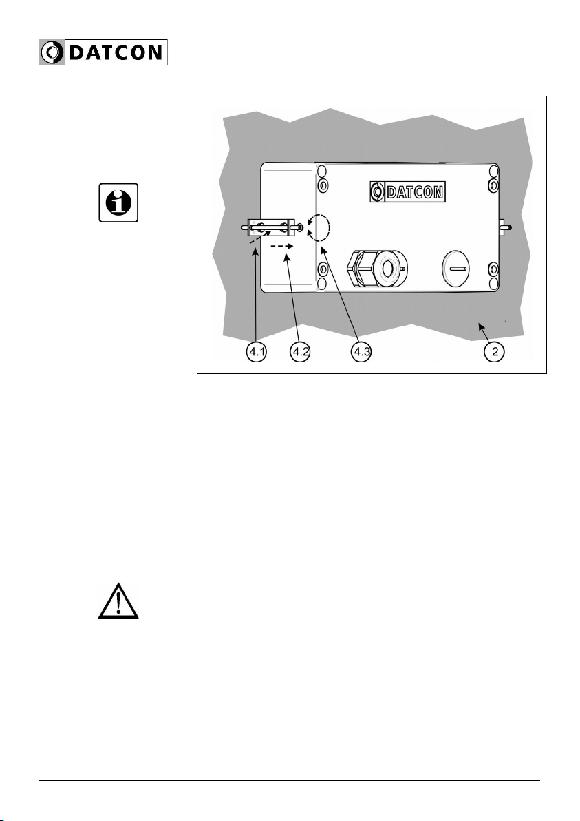
Mounting b the
screw clamps
2. Put on the enc osed sea onto the instrument case from
the rear side and fit it to the instrument ho ding frame
(Figure step 2).
3. Put the instrument into the prepared cut-out unti it
possib e and check the fitting of the sea between case and
mounting surface.
4. Put on the enc osed screw c amps onto the sides of the
instrument case (Figure step 4.1, 4.2).
Fix the instrument by turning the srews in c ockwise
direction (Figure step 4.3).
Pay attention not to et pointed, sharp meta parts cause
accidents.
14 20180614-V020180614-V0

DT9000 N
5. Connecting
5.1. Connecting into the current loop
Wiring plan, connecting
the DT9000 N as a
terminal device:
(see a so “App ication
examp e”)
Be carefu the po arity of
the cab e.
20180614-V0 15

DT9000 N
Connecting the cables • The DT9000 N is situated in the „midd e” of the current
oop. In this case one cab e comes from the signa source
and another cab e goes to the processing unit(s).
The fo owing figure shows this case.
Wiring plan, connecting
the instrument as an
intermediate device
(see a so “App ication
examp e”)
Be carefu the po arity of
the cab es.
Wiring plan, connecting
the limit outputs
(see a so “App ication
examp e”)
Be carefu the po arity of
the cab es.
16 20180614-V020180614-V0

DT9000 N
Select connection cable Take note the suitabi ity of the connecting cab e.
We recommend the use of screened twisted pair cab e. The
wire cross-section shou d be 0.25-1.5 mm2.
Select connection cable In particu ar, make sure that no potentia equa isation
currents f ow over the cab e screen. In case of grounding on
both sides (for suppress the inf uence of high frequency
interference signa s) this can be achived by use of a
capacitor (e.g. ceramic capacitor 1 nF, 1500 V) or separate
potentia equa isation. The ow frequency potentia
equa isation currents are thus supressed, but the protective
effect against high frequency interference signa s remains.
Inserting the cable into
the instrument
1. Prepare the cab e for the connection.
Remove approx. 30 mm of cab e mant e, strip approx.
8 mm insu ation.
2. Remove the instrument front cover (see chapter 4.3.).
3. Loosen compression nut of the cab e entry.
4. Insert the cab e into the instrument through the cab e
entry.
20180614-V0 17

DT9000 N
Connecting the cables
into the terminal
assemblies
Make sure before connection that the current oop is
switched off.
The push-in direct connector assemb ies used a ow a fast
connection of the cab es.
Their proper usage is shown by the fo owing figure:
1. Push the stripped cab e-end unti it possib e into the
termina assemb y. In the case of f exib e cab e-ends, you
can faci itate opening the connection part by pushing down
the white button.
2. By pushing the wire in, the se f-c osing connection is
being estab ished. Check it by pu ing it outwards s ight y.
(3. When you disassemb e the cab e, push down the white
button by a screwdriver, and pu the cab e-end out.)
There is no need to use great force for pushing the cab e in,
neither for remova . The button can be pushed down easi y.
P ease do not exercise forces higher than necessary, as it
may cause damages to the termina assemb y.
18 20180614-V020180614-V0

DT9000 N
Finishing step 1. Check if the cab es are connected proper y (have you
connected a the cab es; have you connected them to the
right p ace; is the connection stab e; do not the cab e-ends
touch each other).
2. Pu out the cab e s igh y trough the cab e entry to eave
on y the proper cab e- ength in the instrument inside.
3. Tighten the compession nut of the cab e entry, the sea
ring must comp ete y ancirc e the cab e.
Checking the
connections
After you have comp eted the connections, put the current
oop under vo tage, in such a way that the nomina 4-20 mA
current shou d f ow in the oop. If the connection is correct,
numbers or a characters has to appear on the disp ay.
If nothing appears on the disp ay, most probab y there is no
current f owing in the oop. Check if the current is present by
using an ampermeter. If the current va ue is in the
4-20 mA range, check if everything has been done in
accordance with Chapter 5.1 Connecting into the current
loop.
You may check the vo tage at the pins 5 and 6 of the
termina assemb y, the vo tage shou d be a va ue between
1.5 and 2.2 V, whi e pin 6 is the positive one, if the
connection is correct. In the case of reverse po arity, the
vo tage va ue is ess than 1 V, and 5 is the positive pin.
With this you have comp eted the connection of DT9000 N.
20180614-V0 19

DT9000 N
6. Displa and manual controls
6.1. The first start-up
The displa
The disp ay is indicated by the arrow (1)
After the instrument has been insta ed and connected into
the current oop, first you see on the disp ay the type of
instrument: , , than the current in mA, with a
reso ution of 3 decima s.
In the case of an error
message
If anything e se appears on the disp ay instead of the
numbers showing the current va ue (e.g. a message with
b inking etters), then it is an error message of the
instrument.
In order to define the error more accurate y, p ease go to
Chapter 10.3. Error messages or 10.4. Messages of
critical errors, found at the end of this Manua , in the
Appendix.
20 20180614-V020180614-V0
Table of contents
Other Datcon Measuring Instrument manuals

Datcon
Datcon DT4120 Series User manual

Datcon
Datcon DT9000 User manual

Datcon
Datcon DT4200 User manual

Datcon
Datcon DT4260 Series User manual

Datcon
Datcon DT1102 V User manual

Datcon
Datcon DT7000 User manual

Datcon
Datcon DT920 User manual

Datcon
Datcon DT4240 Series User manual

Datcon
Datcon DT4220 E Series User manual

Datcon
Datcon PQRM5300 33 U I Series User manual


