Datcon DT9500 User manual

DT9500
Intrinsically Safe Temperature Meter / Transmitter
Operating Instructions

DT9500
2 20220103-V2
Contents
1. About this document .....................................................4
1.1. Function ................................................................................... 4
1.2. Target group............................................................................. 4
1.3. Symbolism used....................................................................... 4
2. For your safety ...............................................................5
2.1. Authorised personnel ............................................................... 5
2.2. Appropriate use........................................................................ 5
2.3. Warning about misuse ............................................................. 5
2.4. General safety instructions....................................................... 5
2.5. CE conformity........................................................................... 5
2.6. Safety information for Ex areas................................................ 6
2.7. Environmental instructions ....................................................... 6
3. Product description .......................................................7
3.1. Delivery configuration............................................................... 7
3.2. Principle of operation ............................................................... 7
3.3. Settings .................................................................................... 9
3.4. Storing and transporting........................................................... 9
4. Mounting.......................................................................10
4.1. General instructions ............................................................... 10
4.2. Main dimensions of the instrument. ....................................... 10
4.3. Mounting as a wall-instrument ............................................... 11
4.4. Mounting as a panel-instrument............................................. 14
5. Connecting ...................................................................16
5.1. Connecting into the current loop ............................................ 16
6. The display and the operating devices......................22
6.1. The first start-up ..................................................................... 22
6.2. Characters and mnemonics appearing on the display ........... 23
6.3. Manual controls...................................................................... 26

DT9500
20220103-V2 3
7. Setting-up .....................................................................29
7.1. Typing the code (password) in ............................................... 29
7.2. The menu ............................................................................... 31
7.3. Display modes of limit output status (01. menu item) ........... 32
7.4. Setting up the limit outputs (02. & 03. menu items) ............... 34
7.5. Limit output alarm mode......................................................... 40
7.6. 4-wire / 3-wire operating modes (04 menu item).................... 42
7.7. The temperature value belonging to the 4 mA value
(05 menu item) .............................................................................. 43
7.8. The temperature value belonging to the 20 mA value
(06 menu item) .............................................................................. 45
7.9. The number of averaged measurements (07. menu item)..... 47
7.10. Display refresh time (08. menu item) ................................... 49
7.11. Tests (09. menu item) .......................................................... 51
7.12. Changing the user code (10. menu item)............................. 54
7.13. Changing the supervisor code (11. menu item) ................... 56
7.14. Display operating modes (12. menu item) ........................... 58
7.15. Disable displaying the leader zeros (13. menu item) ........... 60
7.16. Clear minimum and maximum values (14. menu item)........ 62
7.17. Resetting the default settings (15. menu item)..................... 63
8. Fault rectification .........................................................64
8.1. Fault finding............................................................................ 64
8.2. Repairing................................................................................ 64
9. Dismounting .................................................................64
9.1. Dismounting procedure .......................................................... 64
9.2. Disposal ................................................................................. 64
10. Appendix.....................................................................65
10.1. Technical specifications ...................................................... 65
10.2. Application example ............................................................. 67
10.3. Error messages.................................................................... 68
10.4. Messages of critical errors ................................................... 69
10.5. Description of the menu items.............................................. 70
10.6. Messages and error messages during setting up ................ 73
10.7. Setting up the apparatus (practical exercise)....................... 74
10.8. The limit outputs (training material)...................................... 76
10.9. ATEX Certification................................................................ 87

DT9500
4 20220103-V2
1. About this document
1.1. Function
This operating instructions manual has all the information
you need for quick set-up and safe operation of DT9500.
Please read this manual before you start setup.
1.2. Target group
This operating instructions manual is directed to trained
personnel. The contents of this manual should be made
available to these personnel and put into practice by them.
1.3. Symbolism used
Information, tip, note
This symbol indicates helpful additional information.
Caution, warning, danger
This symbol informs you of a dangerous situation that
could occur. Ignoring this cautionary note can impair the
person and/or the instrument.
Ex applications
This symbol indicates special instructions for Ex
applications.
•
List
The dot set in front indicates a list with no implied
sequence.
→
Action
This arrow indicates a single action.
1
Sequence
Numbers set in front indicate successive steps in a
procedure.

DT9500
20220103-V2 5
2. For your safety
2.1. Authorised personnel
All operations described in this operating instructions
manual must be carried out only by trained and authorised
specialist personnel. For safety and warranty reasons, any
internal work on the instruments must be carried out only
by DATCON personnel.
2.2. Appropriate use
The apparatus DT9500 is a loop-powered intrinsically safe
temperature meter and transmitter, that can be used in the
explosive zones of „1” or „2”, as well as in the safe area. Its
input is suitable for the connection of standard Pt 100
measuring probes, which can be connected by four wires
and by three wires too. The sensor can be in zone 0 too.
The instrument presents the temperature measurement
results in digital format with an accuracy of decimals of
degrees, in its LCD display. Between two settable
temperature values it takes a linear 4-20 mA current signal
from the power supply unit (transmitter function). Detailed
information on the application range of the DT9500 is
available in chapter "Product description".
2.3. Warning about misuse
Inappropriate or incorrect use of the instrument can give
rise to application-specific hazards, or demage to system
components through incorrect mounting or adjustment.
2.4. General safety instructions
The DT9500 is a high-tech instrument requiring the strict
observance of standard regulations and guidelines. The
user must take note of the safety instructions in this
operating instructions manual, the country-specific
installation standard as well as all prevailing safety
regulations and accident prevention rules.
2.5. CE conformity
The DT9500 is in conformity with the provisions of the
following standards:
MSZ EN IEC 61326-1:2021 (EMC)
MSZ EN IEC 60079-0:2018 (ATEX)
MSZ EN 60079-11:2012 (ATEX)
MSZ EN 61010-1:2011 (biztonság)

DT9500
6 20220103-V2
2.6. Safety information for Ex areas
Please note the Ex-specific safety information for
installation and operation in Ex areas. These safety
instructions are part of the operating instructions manual
and come with the Ex-approved instruments.
2.7. Environmental instructions
Protection of the environment is one of our most important
duties.
Please take note of the instructions written in the following
chapters:
•Chapter 3.4. Storage and transport
•Chapter 9.2. Disposal

DT9500
20220103-V2 7
3. Product description
3.1. Delivery configuration
Delivered items The scope of delivery encompasses:
•DT9500
•2 pcs. of srew clamps (only panel mounting version)
•1 pcs. M16x1,5 cable entries
• instrument sealing (only panel mounting version)
•documentation:
this oparating instructions manual
certification
warranty
The instrument is built from the following main parts:
Main parts
1. instrument case
2. front panel with 3 membrane push buttons
3.2. Principle of operation
Application fields The apparatus DT9500 is a loop-powered intrinsically safe
temperature meter and transmitter instrument, fed by 4–20
mA loop current. It works with a standard Pt100 measuring
probe, which is not an accessory of the instrument. The
device presents the temperature measurement values in
digital format with an accuracy of decimals of degrees, in
its LCD display. Between two settable temperatures values
it takes a 4 – 20 mA linear current signal from the power
supply unit. (Transmitter function).

DT9500
8 20220103-V2
It contains two limit outputs with selectable operating
modes, therefore it is suitable for simple control operations
too (e.g. temperature regulation).
Due to the function of DT9500 it can be placed in zone 1 or
zone 2. The temperature sensor can be in zone 0 too.
Operating principles
A current generator (800 A) is connected to the terminal
pair PI+ and PI-.
In the case of four-wire measurements, the instrument
measures the voltage appearing in the terminal pair Pt+
and Pt-. This solution ensures that the resistances of the
lines and contacts do not influence the measurement.
In the case of three-wire measurements, the line Pt+ is not
in use. The voltage between Pt- and PI- is deducted from
the voltage between PI+ and Pt-. This way when the
resistances of PI- and PI+ lines are identical with each
other, the voltage dropping in these lines does not
influence the accuracy of the measurement.
A built-in microprocessor is used to calculate the
temperature values. The results are presented on a 4-and-
half-digit LCD display. The limit outputs work in accordance
with the displayed temperature values.
The 4–20 mA current of the transmitter output could be
assigned to any temperature range. This way the best
possible settings could be achieved for a given application.
By press-buttons located on the front panel, the
temperature values assigned to the 4 mA transmitter
current and to the 20 mA current could be selected
separately.
The apparatus has a „sink” type output, requiring external
power supply. This current ensures, at the same time, the
power supply for the apparatus too, and thus the device
connects to the receiving unit by two wires (+I, -I).
Power supply There should be minimum 12 V voltage on the terminals of
the apparatus.

DT9500
20220103-V2 9
3.3. Settings
DT9500 can be adjusted through the 3 button front panel
keypad. All configuration parameters are stored in the
instrument EEPROM for unlimited period of time, even
when the power supply beeng switched off.
According to the default factory setting, the probe Pt100 is
connected in 4-wire mode. For the transmitter -200 ºC is
assigned to 4 mA, and +600 ºC is assigned to 20 mA. The
number of averaged samples is 8, the display refreshing
time is 0.5 sec
After the apparatus has been installed, it is functionable
immediately, without any further settings.
Re-scaling the transmitter, or changing other factory default
settings (e.g. setting the device to 3-wire operating mode)
could be performed simply and easily by using the press-
buttons on the front panel. The instrument doesn't need
any internal adjustment.
3.4. Storing and transporting
This instrument should be stored and transport in places
whose climatic conditions are in accordance with Chapter
10.1. Technical specifications, as described under the
title: Environmental conditions.
The packaging of DT9500 consist of enviroment-friendly,
recyclable cardboard is used to protect the instrument
against the impacts of normal stresses occurring during
transportation. The corrugated cardboard box is made from
environment-friendly, recyclable paper. The inner
protective material is polyfoam and nylon, which should be
disposed of via specialised recycling companies.

DT9500
10 20220103-V2
4. Mounting
4.1. General instructions
Use the enclosed seal when mounting DT9500 on panel to
assure IP 65 protection between the instrument and the
panel from the front side (only panel mounting version).
Electrostatic hazard! Clean only a moist cloth and
detergent.
Mounting positions
Select a mounting position you can easily read the display
reach for mounting and connecting the instrument and that
minimises the hazard of water, dust or dump getting into
the instrument.
Mounting cable entries
The insrument is equipped with two PG11 cable entry and
one additional hole equipped with sealing plug. One PG11
cable entry is accessory. If required more than two cable
entry (see chapter 5.) put out the sealing plug turning it in
anticlockwise direction. To put in the cable entry use the
sealing turn it in clockwise direction. Tighten the screws so
much that ensures the desired sealing. Use only appropriet
tools.
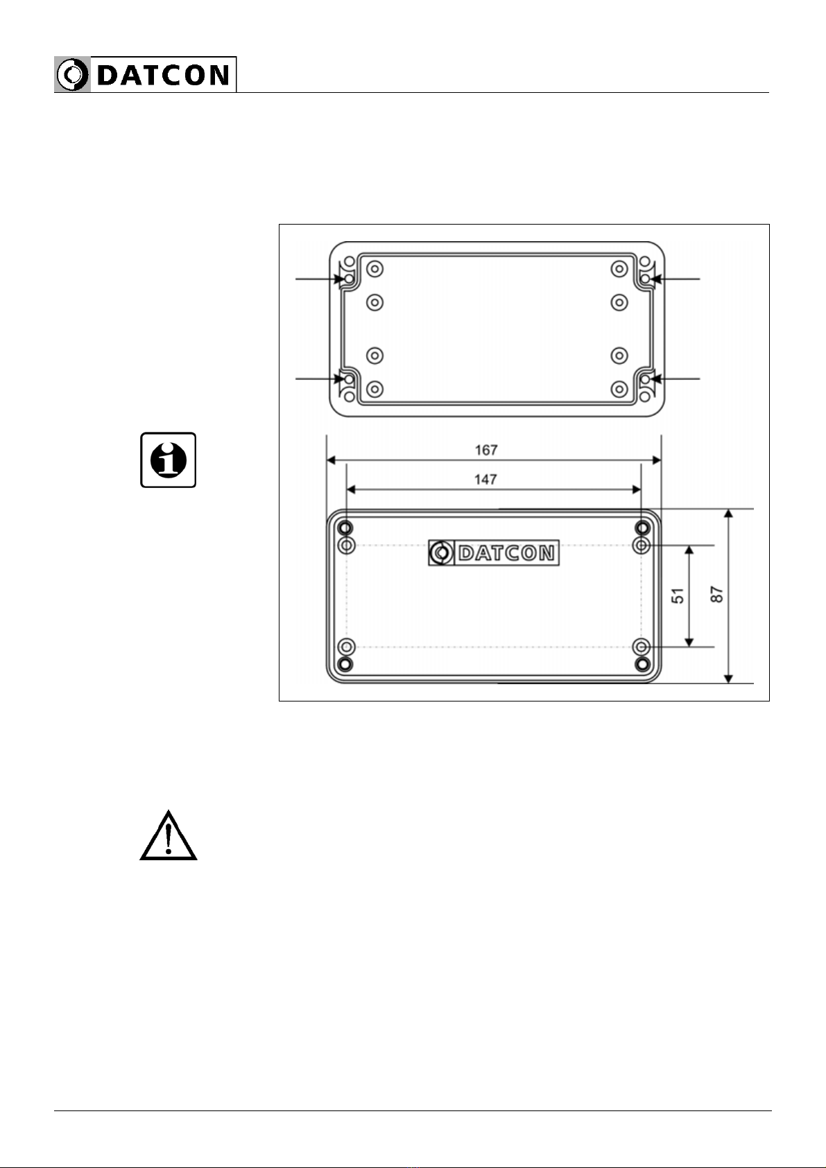
4.2. Main dimensions of the instrument.

DT9500
20220103-V2 11
4.3. Mounting as a wall-instrument
Removing the front
cover
In order to remove the front cover, first remove the four
fixing screws as shown in the drawing. A screwdriver of
appropriate head-size only should be used. Using
screwdrivers with inappropriate head-size may cause a
damage in the screws’ heads or in the instrument front
panel.
Remove the screws by turning them in anticlockwise
direction as shown in the drawing Step (1). The screws are
secured against falling out. After this you can simply take
away the front cover from the housing (2) and you can
open it by turning it downwards (3). Plastic ties are used to
fasten the front cover to the housing, preventing it from
falling.
DT9500
12 20220103-V2
Preparatory steps There are four through-holes, shown by arrows in the
following drawing, for the fastening of the housing. The
diameters of the holes are made for M3 screws.
Holes for mounting
1. Mark the places of the holes in accordance with the
drawing.
2. Make the holes for mounting ready.
3. Remove any burrs from the ready-made holes.
Please observe the safety rules throughout the operation.

DT9500
20220103-V2 13
Mounting the instrument
Four M3 threaded screws are needed for mounting the
instrument (these are not accessories). The type of the
screws depends on the wall-material, while the dimensions
depend on the wall-thickness. The use of cross recessed
pan head screws is recommended to make the mounting
easier. The minimum screw-length should be the wall-
thickness + 10 mm.
During mounting, please observe all safety rules, and use
only appropriate tools.
Secure the screws against getting loose. For this purpose
you may use spring lock or serrated lock washers.
Depending on the material of the wall, and in order to
ensure the most practicable mounting method, it is not
mandatory, of course, to use the above-described threaded
joints. Depending on the situation, special screw types for
wood or for metal sheets can also be used, or the joint can
be riveted too.
Mounting the front cover
back to its place
1. Check if there are alien materials left in the housing, like
small tools, wire or metal pieces, plastic chips, etc. If there
are, remove them.
2. Put back the front cover of the apparatus, taking care
that the sealing should get to its place. There should be no
gap, nor cables caught between the housing and the front
cover.
3. Tighten the front cover.
Turn the screws in clockwise direction. Tighten the screws
so much that ensures the desired sealing.

DT9500
14 20220103-V2
4.4. Mounting as a panel-instrument
Preparatory steps
1. Cut-out the panel according to the figure shows below.
The cut-out needs spetial tools, it must be carried out by
trained specialist personnel.
Cut-out dimensions

DT9500
20220103-V2 15
Mounting by the
screw clamps
2. Put on the enclosed seal onto the instrument case from
the rear side and fit it to the instrument holding frame
(Figure step 2).
3. Put the instrument into the prepared cut-out until it
possible and check the fitting of the seal between case and
mounting surface.
4. Put on the enclosed screw clamps onto the sides of the
instrument case (Figure step 4.1, 4.2).
Fix the instrument by turning the srews in clockwise
direction (Figure step 4.3).
Pay attention not to let pointed, sharp metal parts cause
accidents.

DT9500
16 20220103-V2
5. Connecting
5.1. Connecting into the current loop
In hazardous areas you should take note of the appropriate
regulations, conformity and type approval certificates of the
DT9500 and other instruments are connecting in the
current loop (e.g. power supply, transmitter, etc.).
The connection must be carried out by trained and
authorised personnel only!
Select connection cable
A four-wire, twisted pair, shielded cable should be used for
connecting the measuring probe Pt100 to the apparatus. It
is also possible to use three-wire cables, but the
measurement accuracy will deteriorate due to the
asymmetry of the resistances of wires, and due to the
incertainty of contact resistances.
For connecting the loop-feeding, a two-wire, twisted pair,
shielded cable must be used.
For connecting the limit-value outputs, two-wire, twisted
pair cable with 500 V insulation may be used.
The internal cable diameter is 0,25–1,5 mm, the external
cable diameter is 5–10 mm.

DT9500
20220103-V2 17
Connection
4-wire mode •The shieldings of the cables connected to Pt100 and to
the current loop must be connected with each other.
(see also “Application
example”)
Be careful the polarity of the cables.
The most accurate measurement can be achieved by the
4-wire operating mode, as the cable resistances and their
possible asymmetry will not cause measuring errors.
In order to ensure accurate measurement its usage is
absolutely recommended.

DT9500
18 20220103-V2
Connection
3-wire mode •The shieldings of the cables connected to Pt100 and to
the current loop must be connected with each other.
(see also “Application
example”)
Be careful the polarity of the cables.
The 3-wire operating mode results in less accurate
measurement than the 4-wire operating mode, as the
different resistances of the cable wires, their asymmetry,
and the various temporary resistance values of contacts
cause additional measurement errors. The use of this
mode is recommended only for those cases that are
satisfied by less accuracy.
In all other cases it is practicable to use the 4-wire
operating mode (according to the connection depicted in
the previous page).

DT9500
20220103-V2 19
Wiring plan, connecting
the limit outputs
(see also “Application
example”)
Be careful the polarity of the cables.
Select connection cable
Select connection cable
for Ex applications
Take note the suitability of the connecting cable.
We recommend the use of screened twisted pair cable.
The wire cross-section should be 0.25-1.5 mm2.
Take note of the corresponding installation regulations for
Ex applications. In particular, make sure that no potential
equalisation currents flow over the cable screen. In case of
grounding on both sides (for suppress the influence of high
frequency interference signals) this can be achived by use
of a capacitor (e.g. ceramic capacitor 1 nF, 1500 V) or
separate potential equalisation. The low frequency
potential equalisation currents are thus supressed, but the
protective effect against high frequency interference
signals remains.
Inserting the cable into
the instrument
1. Prepare the cable for the connection.
Remove approx. 30 mm of cable mantle, strip approx.
8 mm insulation.
2. Remove the instrument front cover (see chapter 4.3.).
3. Loosen compression nut of the cable entry.
4. Insert the cable into the instrument through the cable
entry.

DT9500
20 20220103-V2
Make sure before connection that the power supply is
switched off.
The push-in direct connector assemblies used allow a fast
connection of the cables.
Their proper usage is shown by the following figure:
Connecting the cables
into the terminal
assemblies
1. Push the stripped cable-end until it possible into the
terminal assembly. In the case of flexible cable-ends, you
can facilitate opening the connection part by pushing down
the white button.
2. By pushing the wire in, the self-closing connection is
being established. Check it by pulling it outwards slightly.
(3. When you disassemble the cable, push down the white
button by a screwdriver, and pull the cable-end out.)
There is no need to use great force for pushing the cable
in, neither for removal. The button can be pushed down
easily. Please do not exercise forces higher than
necessary, as it may cause damages to the terminal
assembly.
Table of contents
Other Datcon Measuring Instrument manuals

Datcon
Datcon DT4240 Series User manual

Datcon
Datcon DT7000 User manual

Datcon
Datcon DT9502 User manual

Datcon
Datcon DT4227 UI User manual

Datcon
Datcon PQRM5300 33 U I Series User manual

Datcon
Datcon DT1102 V User manual

Datcon
Datcon DT4260 Series User manual

Datcon
Datcon DT920 User manual

Datcon
Datcon DT9002 User manual

Datcon
Datcon DT4200 User manual


Popular Measuring Instrument manuals by other brands

Topkodas
Topkodas GTalarm2 Installation & programming manual

LaserLiner
LaserLiner PowerBright-Laser PBL P5 operating instructions

Agilent Technologies
Agilent Technologies 83483A manual

Teledyne SP Devices
Teledyne SP Devices ADQ quick start guide

Amalgamated Wireless
Amalgamated Wireless F242A manual

Tektronix
Tektronix SD-14 Service manual


