daviteq CAP10G User manual
CAP10G-MN-EN-01
OCT-2020
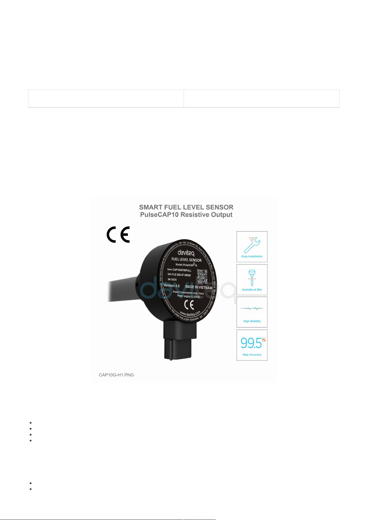
CAP10G is the industrial version of PulseCAP10, designed specifically for generator fuel monitoring applications. The
CAP10 has 240..33 ohms resistor output allowing direct connection to a generator controller. It is compatible with most
popular generator controllers on the market such as DEEPSEA, EMKO, DATAKOM, COM AP, MGS, SMART GEN,
WOODWARD, POWERCOMMAND ... CAP10G with high precision up to 0.5%. Measuring range from 100mm - 3500mm.
The sensor has CE EMC certification according to EN61236-1 standard.
The technicians who install sensor, must be graduated from college of mechanic or electric.
The mechanical installation staff (drill, cut, grind, etc.) must have skills in mechanical engineering.
The electrical installation staff (connect, etc.) must have skills in electrical engineering.
The technician must be trained before using.
CAP10G is intended to use with Diesel Oil, Vegetable Oil.
CAP10G must not be used with other flammable fluid such as Gasoline, Alcohol, Ethanol, Acetone, Toluene or
other solvents.
USER GUIDE FOR FUEL LEVEL
SENSOR RESISTIVE OUTPUT
CAP10G
This document is applied for the following products
1. Introduction
2. Notes
3. Safety
Be careful while drilling, cutting, grinding, etc. The fuel tank or other flammable fluid.
Daviteq is not responsible for compensation in case of explosion to bodily injury or property damage.
Read specifications thoroughly and make sure that its output are suitable to reading devices.
Power supply must be in the permitted range.
Do not take out the label and take off the lid as this will lead to the instability of the sensor and manufacturer
could deny warranty. (except cutting of sensor length within the allowed range).
Make sure all the necessary tools are ready before the installation.
CAP10G be equipped with screws. We advise customers should use stainless steel rivets to fasten
the plastic flange onto tank for all type of tanks and only using screws for the thick and hard ones.
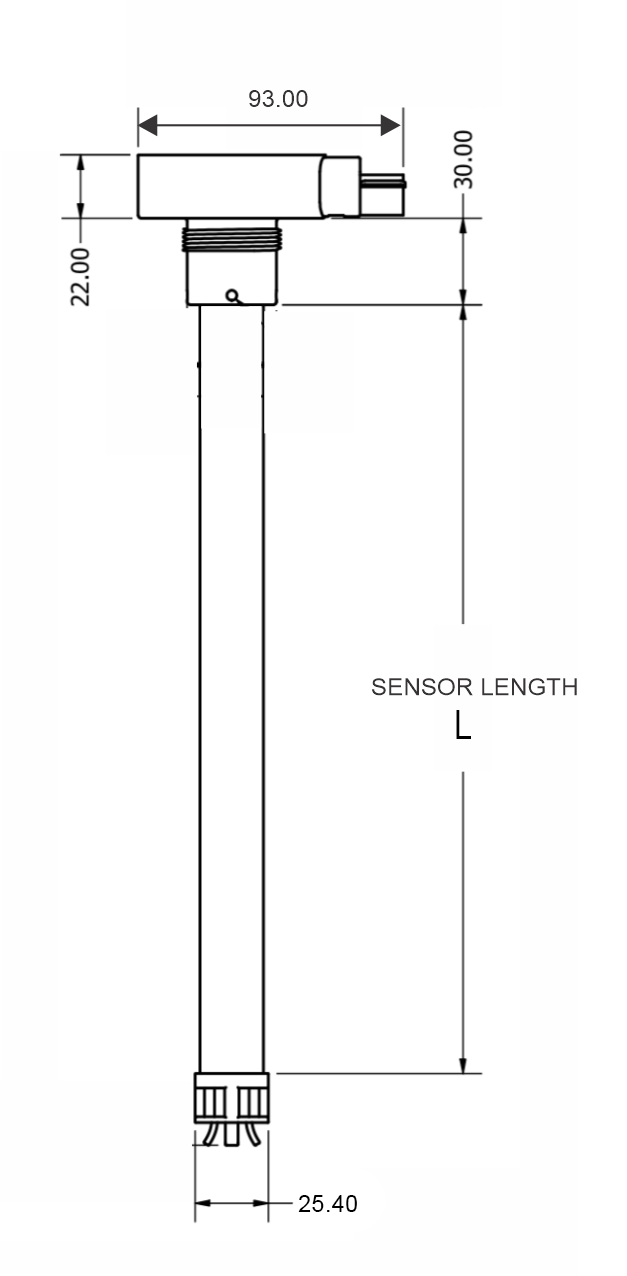
Sensor length
Standard 700mm, 1000mm, optional 1200 or 1500mm. Cuttable down to
200mm. Longer than 1500mm, suggest to use Industrial type sensor
CAP10CN
Output
240..33 ohms
Power supply
8..50VDC
Consumption
max 20mA
Working pressure
-1 .. 2 barg
Working temperature
-40 oC .. + 85 oC
Accuracy
+/- 0.5% of span (at 25 oC)
Temperature drift
< + 0.03% of span per 10oC
Resolution
1/1000 of span
Sensor materials
Alloy & Engineering plastic
Electrical connection
3-way connector IP67 from MOLEX with 3m shielded cable as standard
Housing
Cast alumium, IP67 protection
Process connection
Plastic flange
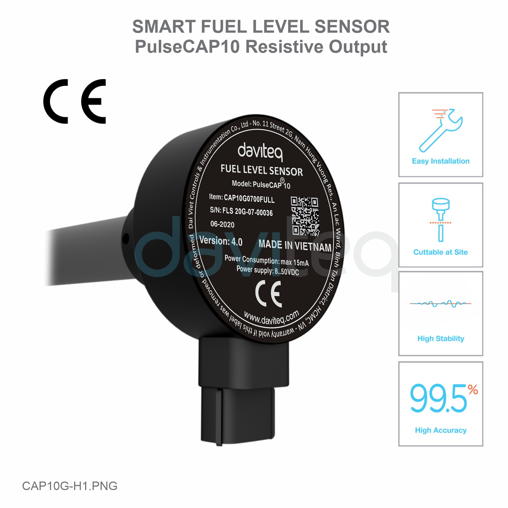
Standard accessories
flange, o-ring, gasket, protection covers, self-tapping screws, twisted
seal, fuse & fuse holder
Certification
CE-Marking per EN61236-1 (with test report)
4. Note Before Installation
5. Specification
6. Full Package

No
Tool Name
No
Tool Name
01
Drilling machine
10
Drill (Φ38)
02
Pump
11
Silicone gasket
03
Rivet clippers
(In case of using stainless steel
rivet)
12
Twist drill 4 mm
(In case of using stainless steel
rivet)
04
Tube cutter
13
Electrical tape
05
Swivel Blade
14
Cutting pliers
06
Hacksaw
15
Phillips screwdriver
07
File
16
Pencil
08
Tape measures
17
Multi Meter
09
Allen key 2 mm
18
Calibration can
7. Tools

Step
Discription
Note
1
Remove fuel: Remove all fuel from the tank.
Some tank have been welded with oil filter and
have float level sensor installed, so it is
necessary to take out the float level sensor
before removing the fuel.
2
Clean the tank
Must clean the tank thoroughly.
3
Central hole locating: The hole will be in the
center of tank's up-per side or closest to
center.
This is an important step as it will directly
affect the stability of the fuel level data.
4
Drilling the central hole:
After determining the center of the oil
tank, we clean the surface and use a 38
mm drill to make a hole on the oil tank.
Remove any burrs from the drilled hole
by a file.
Before drilling, it is vital to check whether the
hole is affected by the internal metal frame or
obstacles at the bottom the tank.
5
Flange installation:
Place the 4 mm rubber gasket at the
center of the tank's upper side.
Place the plastic flange onto the rubber
gasket (4 mm).
Mark 4 points at the bolt hole.
Use screws /rivets to fasten the 4 mm
rubber gasket and the plastic flange
onto tank.
Only using screws for the thick and hard
tanks.
Unplug the screw/ rivet symmetrically.
8. Sensor Installation Guidance

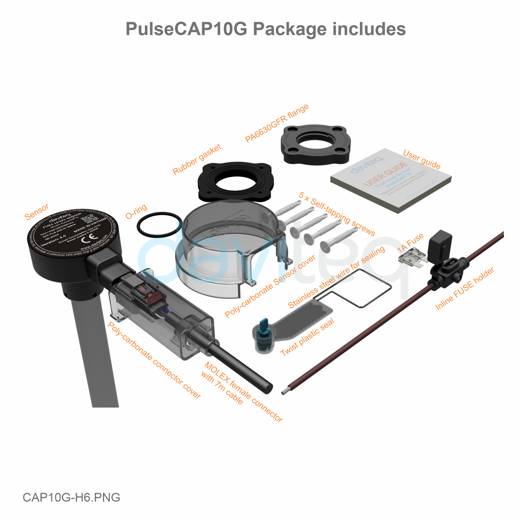
6
Sensor cutting:
After flange installation, we determine the length of the sensor to be installed as picture below:
C = L+20+20-(H+14) => C = L+26-H (mm)
C: Length to be cut.
L: Original length of the sensor.
H: Height of the tank.
*Example:
Sensor length is L = 2000, H = 1700 mm => C = 326 mm => Cut the sensor pipe length of 326
mm.
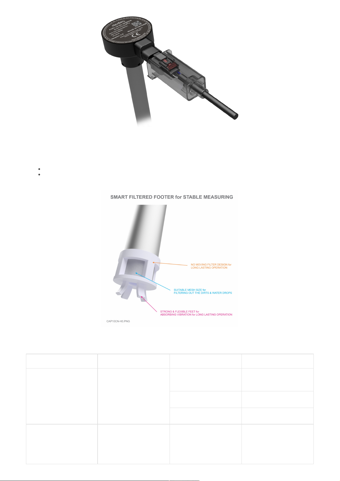
7
Calibration:
After cutting, make sure the sensor tube is clean.
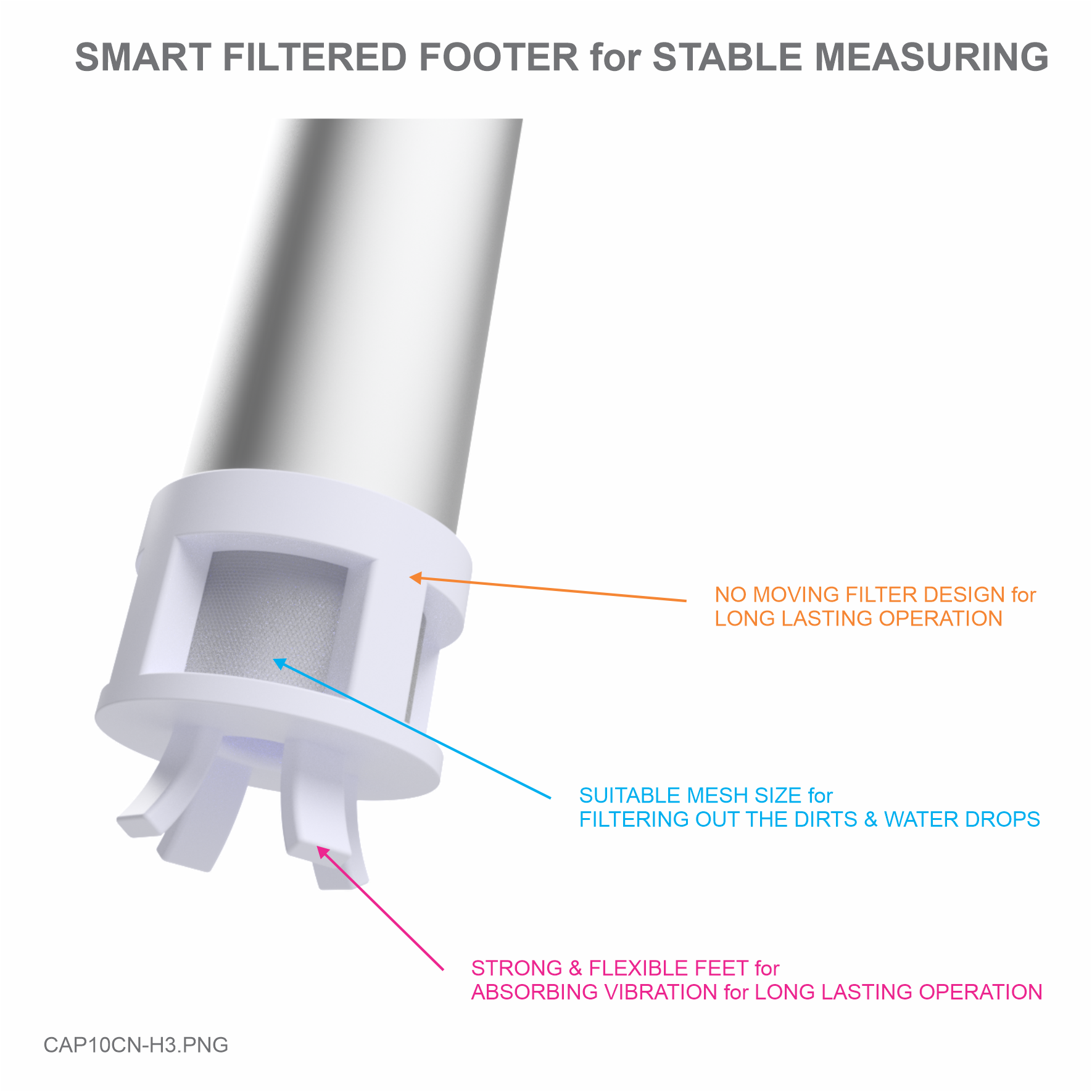
Re-plug the Filter footer and tighten the screw.
Turn on the sensor in at least 30 seconds in order for the sensor to automatically
recognize its new length.
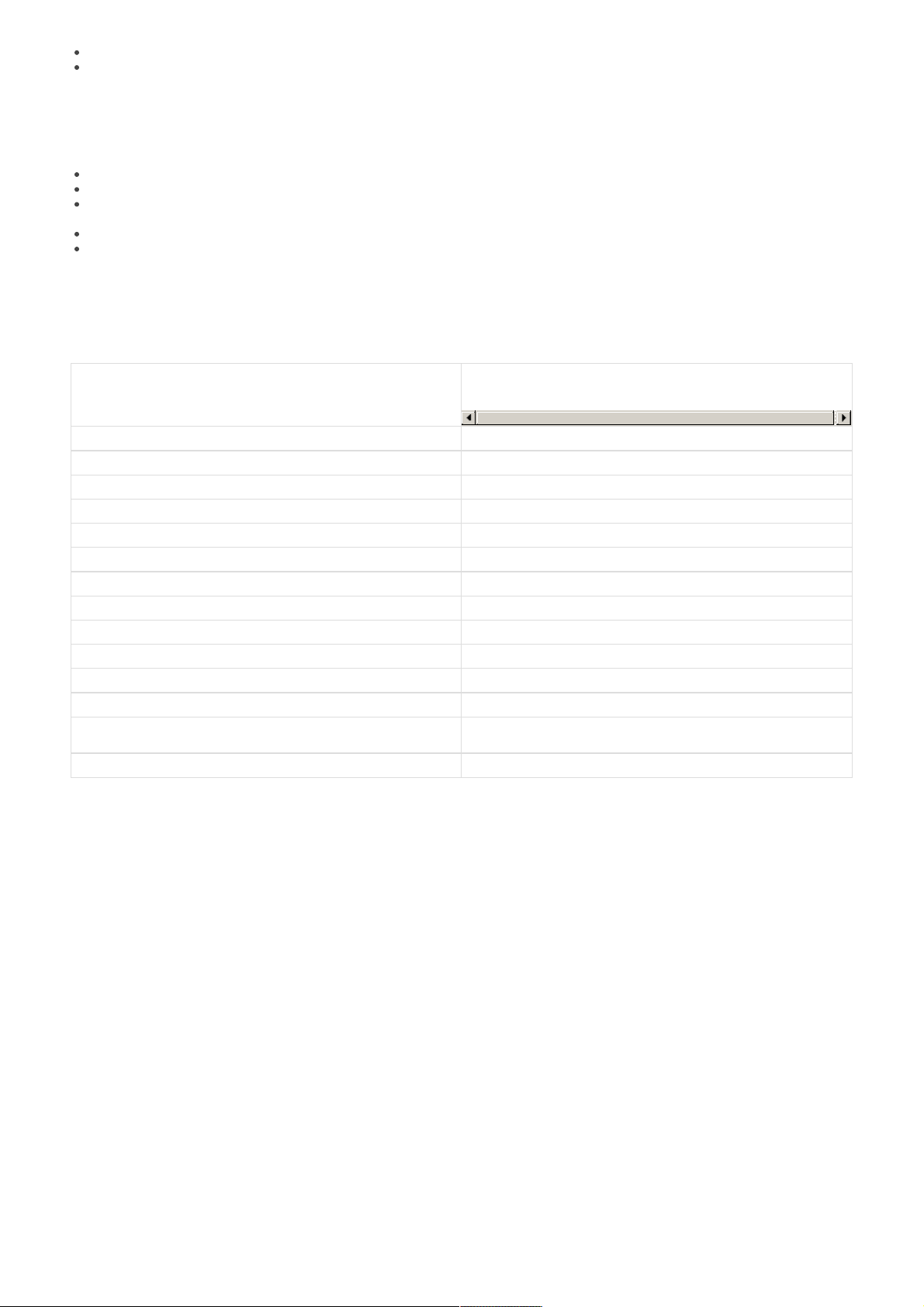
8
Final:
Place the O-ring on the top of the threads, ensure that it can touch the aluminum housing
of the sensor (as below picture):
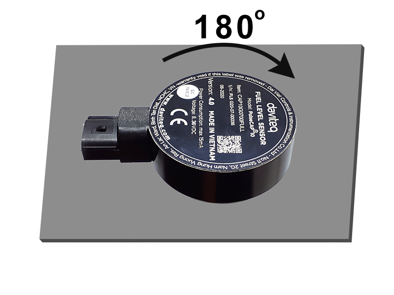
Install sensor into the threads of flange and turn it in clockwise direction.
Using the O-ring enables to rotate the sensor within 180 degrees from final tighten
position and assuring that the oil will be not spilled (as below picture):
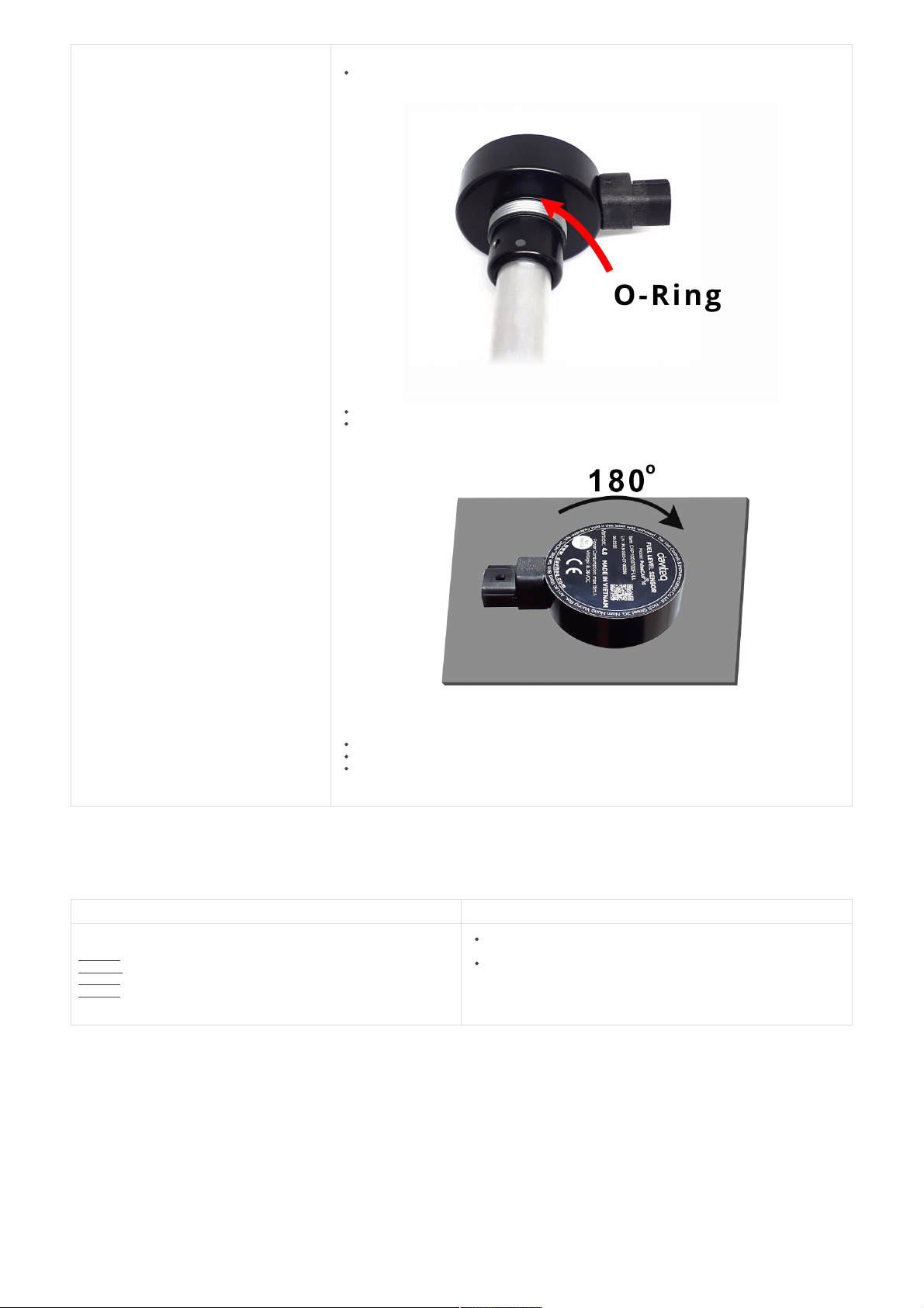
Use the 2mm Allen key to lock the hex bolt to protect the sensor rotate backwards.
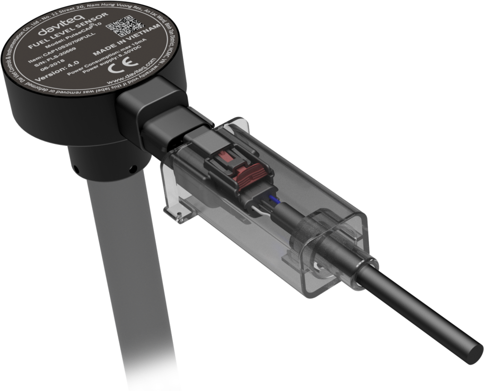
Connect the sensor with the cable.
Use sensor head seal to cover the sensor and then use plastic and then use plastic twister
seal to lock the head seal and connector seal to protect the sensor.
Please follow the below steps:
Note
Step 1: Remove the cover
Step 2: Remove the terminal connector
Step 3: Use the 2 mm Allen key to unlock the hex bolt
Step 4: Turn the sensor in counter-clockwise direction
Do not hold the male connector to rotate sensor directly, that
can make the male connector broken.
Do not use locking pliers, pipe wrenches, etc. to twist the sensor
as this cause damages the structure of the sensor such as cast
aluminium housing, label, signal cables (connector), circuit
board, ect. and it will not be covered under warranty.
9. Disassembly Guidance
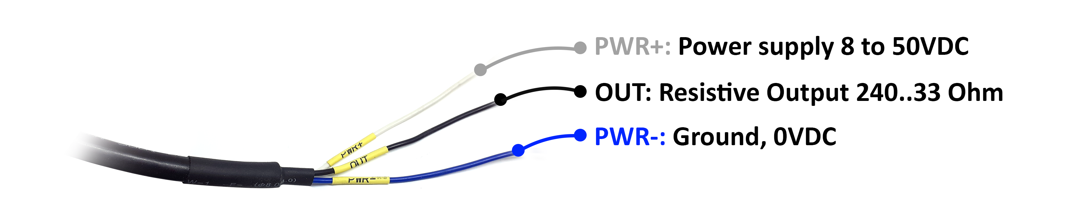
10. Wiring

Each cable includes wires which are marked labels according to types of connection. (user should not cut these labels
before installation to avoid confusing)
White: PWR+(8...50VDC)
Blue: PWR-(OVDC)
Black: Resistive Output (240.33 Ohm)
Recommend to use 24VDC power.
The signal cable from sensor should be protected by corrugated hose or the Φ16 plastic tube, keep the cable avoid
high temperature areas.
10.1 Follow Labels in Wires:
10.2 Follow Wire Colors:
1. Periodically clean the oil tank 2, 3 or 6 months depending on usage and contamination.
2. Periodically clean the sensor and filter footer 2, 3 or 6 months by:
Cover a sensor's vent before using the air sprayer for another.
Remove and clean the filter footer.
No.
Phenomena
Reasons
Solutions
1
No output
Sensor's powering wire is
damaged
Check out on the sensor's
powering wire
Overpowering has burnt the signal
cable and circuit board
Send to manufacturer
Being tampered
Check the seal again before
sending back to manufacturer
2
Signal interference
Sensor was installed too far from
central hole of tank
Install sensor as closest as
possible to the central hole of tank
(the common point of 02
diagonals)
11. Periodic Cleaning Guidance
12. Troubleshooting
3
Unstable output with many
significant strikes
Accesories burnt or there is liquid
inside of board
Send to manufacturer
Connection to power supply is
loose
Check the connection wire
There are impurities in oil tank,
such as: boil, mud, sand, water,...
Clean tank as well as sensor
Warranty is applied for CAP10G fuel level sensor manufactured by Daviteq Technologies Inc (Daviteq).
CAP10G fuel level sensor will be warranted for a period of eighteen (18) months from date of delivery.
1. Manufacturer undertakes to guarantee within 18 months.
2. Product failed due to defects in material or workmanship.
3. Serial number, label, warranty stamp remains intact (not purged, detected, edited, scraped, tore, blurry,
spotty or pasted on top by certain items).
4. During warranty period, if any problem of damage occurs due to technical manufacturing, please notify our
Service Centre for free warranty consultancy. Unauthorized treatments and modifications are not allowed.
5. Product failed due to the defects from the manufacturer, depending on the actual situation, Daviteq will
consider replacement or repairs.
Notes:
One way was shipping cost to the warranty centre shall be paid by Customers.
1. The warranty period has expired.
2. Product is not manufactured by Daviteq.
3. Product failed due to damage caused by disasters such as fire, flood, lightning or explosion, etc.
4. Product damaged during shipment.
5. Product damaged due to faulty of installation, usage or power supply.
6. Product damaged caused by the customer.
7. Product rusted, stained by effects of the environment or due to vandalism, liquid (acids, chemicals, etc.)
8. Product damaged caused by unauthorized treatments and modifications.
Note:
Customers will be subjected to all repairing expense and shipping cost.
If it arises disagreement with company's determining faults, both parties will have a third party inspection
appraise such damage and its decision be and is final decision.
Warranty service support is available from Monday to Friday (excluding Public Holidays as prescribed)
08:00 AM - 12:00 AM
01:30 PM - 05:00 PM
Hotline: +84.906.885.858
13. Warranty
13.1 Free Warranty Condition:
13.2 Paid Warranty
14. Support contacts

Manufacturer
Daviteq Technologies Inc
No.11 Street 2G, Nam Hung Vuong Res., An Lac Ward, Binh Tan Dist., Ho Chi Minh City, Vietnam.
Tel: +84-28-6268.2523/4 (ext.122)
Email: info@daviteq.com | www.daviteq.com
Revision #2
Created Fri, Oct 16, 2020 6:19 AM by Kiệt Anh Nguyễn
Updated Fri, Oct 16, 2020 7:31 AM by Kiệt Anh Nguyễn
Table of contents
Other daviteq Accessories manuals

daviteq
daviteq WSSFC-ULA-01 User manual

daviteq
daviteq WS433-O2 User manual

daviteq
daviteq WSLRW-AG Series User manual

daviteq
daviteq WS433-AC User manual

daviteq
daviteq WS433-M12F-ATE User manual

daviteq
daviteq A420-FCL User manual

daviteq
daviteq LoRaWAN User manual

daviteq
daviteq WSSFC-AC User manual

daviteq
daviteq CAP10 User manual

daviteq
daviteq WSSFC-V1A-025 User manual


Popular Accessories manuals by other brands


WHISPER KOOL
WHISPER KOOL WK 2500 owner's manual
ICON
ICON Mobile Umini VST user manual

Heath Zenith
Heath Zenith Motion Sensor Entryway Light SL-5610/15 quick start guide

MasterChef
MasterChef EH-380-16 instruction manual

HOMEDEPOT
HOMEDEPOT L-BC205PST Use and care guide

In-situ
In-situ Aqua TROLL 500 overview


