daviteq WSSFC-G4F-NH3-8-01 User manual

WSSFC-G4F-NH3-MN-EN-01
DEC-2021
SKU
WSSFC-G4F-NH3
HW Ver.
1.1
FW Ver.
1.0
Item Code
WSSFC-G4F-NH3-8-01
SIGFOX AMMONIA TOILET SENSOR, INTERNAL ANTENNA, TYPE AA BATTERY 3.6VDC, IP67, RC1
zone
WSSFC-G4F-NH3-9-01
SIGFOX AMMONIA TOILET SENSOR, INTERNAL ANTENNA, TYPE AA BATTERY 3.6VDC, IP67, RC2-
RC4 zones
STEP 1: Select RC
1. Select RC zone
RC zones selection 1, 2, 4,... is RCZ1, RCZ2, RCZ4,... (refer to section
6)
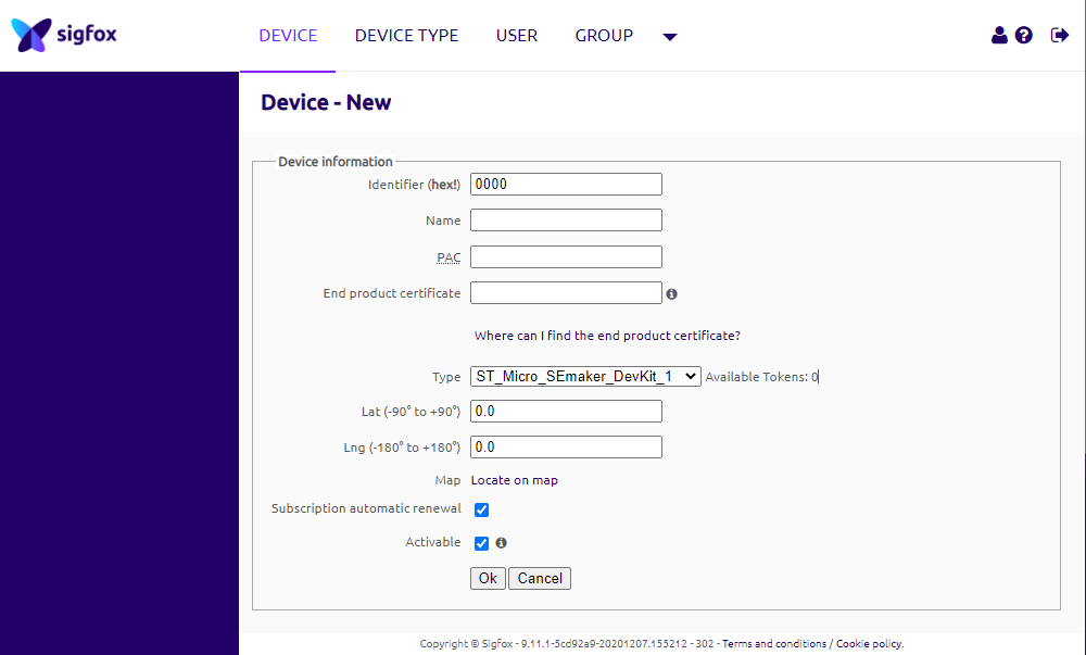
STEP 2: Check ID and PAC
Use Modbus Configuration Cable to read the ID and PAC values
Refer to register address 8 and 10 (DEC)
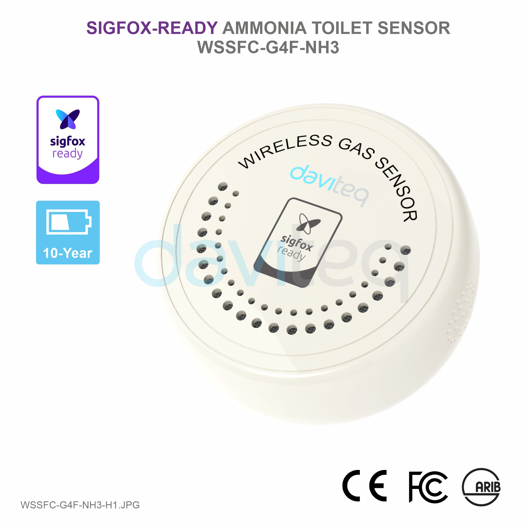
USER GUIDE FOR SIGFOX-READY
AMMONIA TOILET SENSOR WSSFC-
G4F-NH3
This document is applied for the following products
0. Configuration Check List

STEP 3: Configure the sensor's operating parameters
Configure parameters like cycle send data, alarm, a, b,...
Refer to the configuration section 6
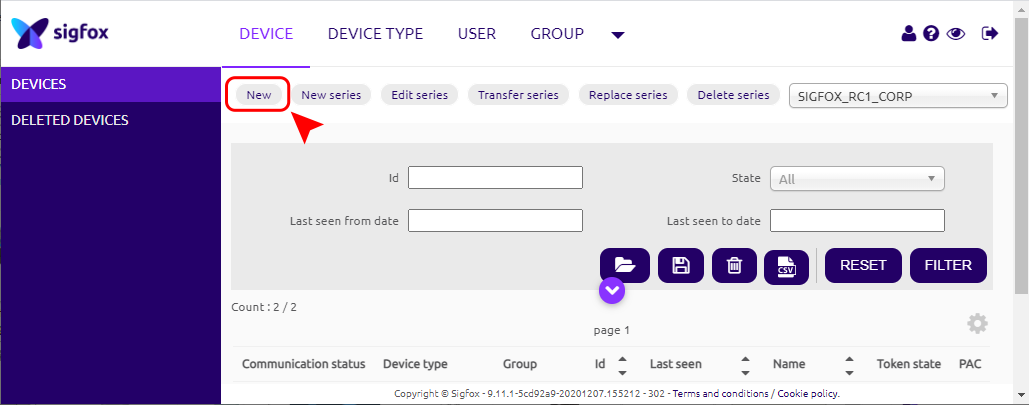
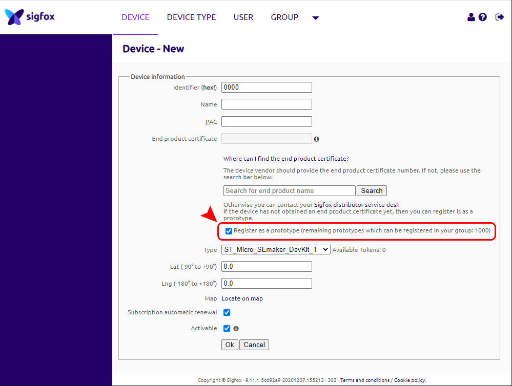
STEP 4: Add device to Backend Sigfox
refer to section 6.2 for details
STEP 5: Installation
refer to section 8 for details
HW Ver.
FW Ver.
Release Date
Functions Change
1.1
1.0
DEC-2020
WSSFC-G4F-NH3 is a Sigfox-ready sensor with built-in electrochemical gas sensor to measure Ammonia NH3 gas
concentration to measure Toilet odor level. With Ultra-low power design and smart firmware allow the complete
Wireless and Sensor package run on 2 x AA battery 1.5VDC for 2-5 years with 15 minutes update. It can support all
regions of Sigfox network in over the World, RC1, RC2, RC3, RC4, RC5, RC6, RC7.
Typical Applications: Monitor Ammonia in private or public toilets.
SENSORS SPECIFICATION:
NH3 sensor
electrochemical-type gas sensor
1. Functions Change Log
2. Introduction
3. Specification

Measuring range for NH3
0..100 ppm
Max detecting concentration
200 ppm
Repeatability / Resolution / Stability per month
< 10% of Reading value / 1 ppm / < 2% of Reading value
Zero stability
+/- 2 ppm
Working atmospheric pressure
101.3 Kpa +/- 10%
Sensor life
> 2 years
Humidity and Temperature sensor
Digital type, factory calibrated
Humidity measuring range / accuracy / resolution
0 .. 100 %RH, ± 2.0% / 0.1%
Temperature measuring range / accuracy / resolution
-40 .. + 85°C / ± 0.2°C / 0.1°C
Working temperature and humidity
-30 .. + 50°C, 15 .. 90% RH
Sigfox SPECIFICATION:
Sigfox zones
select RC1-RC2-RC4
Antenna
Internal Antenna 2dbi
Battery
02 x AA Type 1.5VDC, working time up to 10 years (depends on
configuration)
RF Module complies to
CE, FCC, ARIB
Working temperature
-40°C..+60°C (using Energizer Lithium Ultimate AA battery)
Housing/Protection
ABS
Dimension / Net weight
H180xW73xD42 / < 400 grams
4. Dimensions


After 1 minute 30 seconds later the device will send the first data packet and at the same time wait for the downlink
packet from the Base Station.
Then during the operation, there are 03 cases of sending data to base station:
1. When the sensor sampling time interval is reached, the Sigfox node will read the data from Input or sensor
and performing the calculation. After that it will check calculated value with alarm thresholds. If the calculated
was out off the threshold values (Lo or Hi), called alarm, and the number of times of alarm did not pass the limit
of number of alarms, then it will send data to Base station immediately;
2. When the sending time interval is reached, it will send data to Base station immediately, regardless of value;
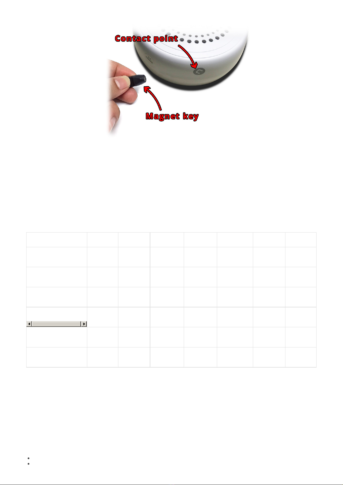
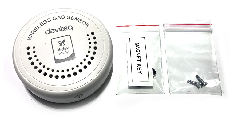
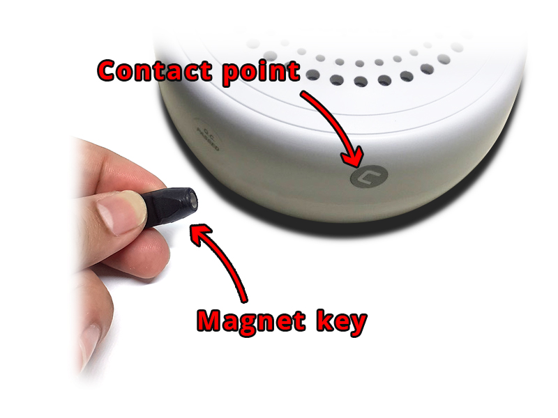
3. By using the magnet key, the Sigfox node can be triggered to send data to base station immediately. There
will be a beep sound from the buzzer meaning the data has been sent.
REED SWITCH
EVENT
PRE-CONDITION
ACTION
BUZZER STATUS
ACTIVITIES
POST-
CONDITION
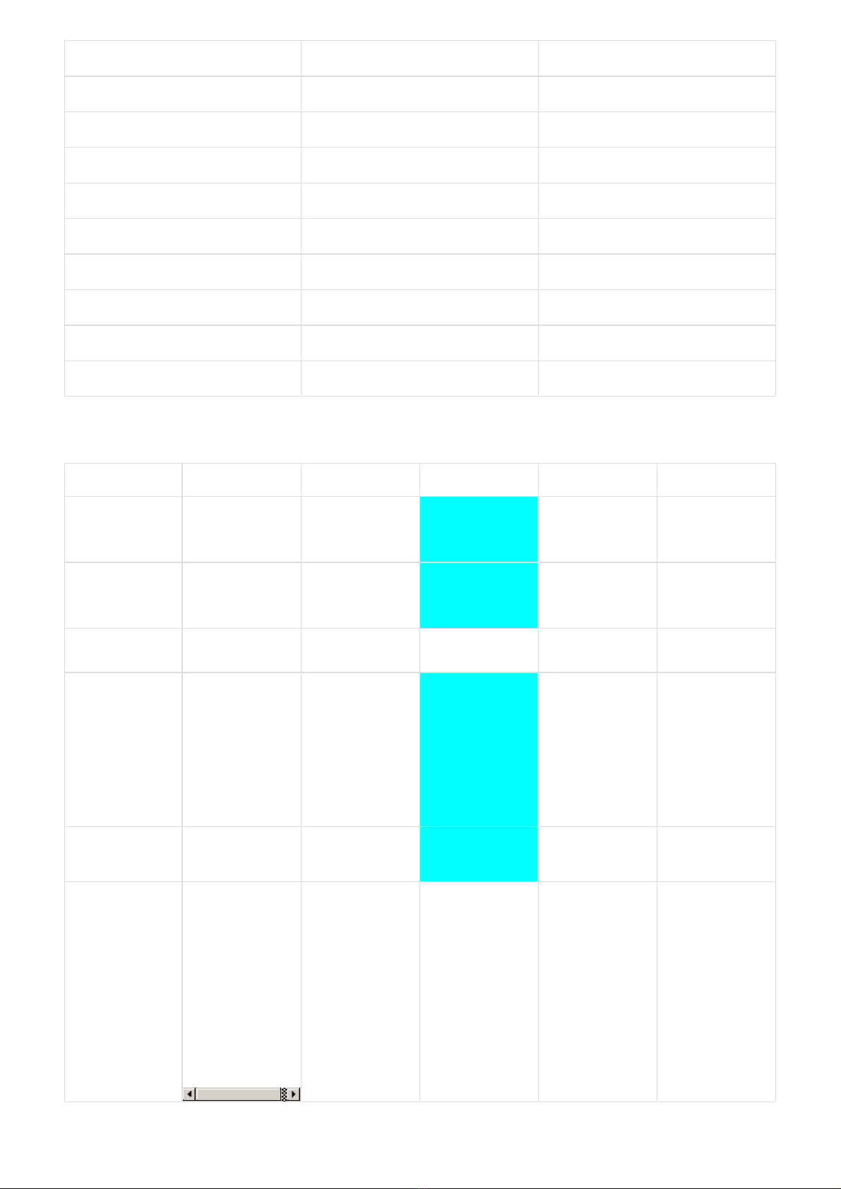
1
FORCE_DATA
Any state
Move Magnet Key
to contact point of
REED SWITCH.
Buzzer beeps 1
time, move
Magnet Key away.
Beep 1 time
To send measured
values
immediately
Back to previous
state
1
PARAMETERS_UPDATE
Any state
Move Magnet Key
to contact point of
REED SWITCH.
Buzzer beeps 1
time, hold Magnet
Key 5s.
Buzzer beeps 2
times.
Beep 2 times
To send current
configuration and
get downlink for
new configuration
Back to previous
state
NOTE:
Once sending the data to base station by this alarm event, the timer of sending time interval will be reset;
NOTE:
Once sending the data to base station by the magnet key, the timer of sending time interval will be reset;
The shortest time interval between the two manual triggers is 5s. if shorter than 5s, there will be no data
sending.
The RF transmit power will be automatically set as the max value as allowed by the Zone.
Sigfox Radio Configuration (RC) defines the radio parameters in which the device shall operate: Sigfox operating
frequencies, output power, spectrum access mechanism, throughput, coexistence with other radio technologies, etc.
Each radio configuration includes 4 uplink classes: 0u, 1u, 2u, and 3u.
The Sigfox network globally works within the ranges from 862 to 928 MHz. But not all RCs require such a wide range of
operation.
RC1
RC2
RC3
RC4
RC5
RC6
RC7
Uplink center frequency
(MHz)
868.130
902.200
923.200
920.800
923.300
865.200
868.800
Downlink center
frequency (MHz)
869.525
905.200
922.200
922.300
922.300
866.300
869.100
Uplink data rate (bit/s)
100
600
100
600
100
100
100
Downlink data rate (bit/s)
600
600
600
600
600
600
600
Sigfox recommended
EIRP (dBm)
16
24
16
24
14
16
16
Specifics
Duty cycle
1% *
Frequency
hopping **
Listen Before
Talk ***
Frequency
hopping **
Listen Before
Talk ***
Duty cycle
1% *
* Duty cycle is 1% of the time per hour (36 seconds). For an 8 to 12 bytes payload, this means 6 messages per hour,
140 per day.
** Frequency hopping: The device broadcasts each message 3 times on 3 different frequencies. Maximum On time
400 ms per channel. No new emission before 20 s.
*** Listen Before Talk: Devices must verify that the Sigfox-operated 200 kHz channel is free of any signal stronger
than −80 dBm before transmitting.
Sigfox’s high limit EIRP recommendation is included in each column although regulations sometimes allow for more
radiated power than the Sigfox recommendation.
Sigfox’s recommendation is set to comply with the Sigfox technological approach of:
Low current consumption
Balanced link budget between uplink and downlink communication
6.1 RC technical details


HEARTBEAT_PERIOD
EVENT_TYPE
HW_VERSION
FW_VERSION
LATEST_SIGFOX_DOWNLINK
HEARTBEAT event is prepared every HEARTBEAT_PERIOD. When the uplink message of the HEARTBEAT event is
prepared, the latest valid configuration that the device has received is provided through the
LATEST_SIGFOX_DOWNLINK field.
The HEARTBEAT event is a Sigfox downlink exchange. Thanks to the downlink message, pre-defined parameters of the
device can be modified in order to change the device behavior.
6.3 Device behavior & Firmware Specification of
NH3 Sensor
Please read
sections 6.5
to 6.8 carefully for a better understanding of the configuration
6.3.1 Heartbeat feature
6.3.1.1 Parameters
6.3.1.2 Payload fields
6.3.1.3 Description
6.3.2.4 Frame

EVENT_TYPE
LATEST_SIGFOX_DOWNLINK
When the appropriate action is done by the user on the Reed Switch 2, a PARAMETERS_UPDATE event is generated.
When the uplink message of the PARAMETERS_UPDATE event is prepared, the latest valid configuration that the device
has received is provided through the LATEST_SIGFOX_DOWNLINK field.
The PARAMETERS_UPDATE event is a Sigfox downlink exchange. Thanks to the downlink message, pre-defined
parameters of the device can be modified in order to change the device behavior.
6.3.1.5 Flowchart
6.3.2 Parameters update feature
6.3.2.1 Payload fields
6.3.2.2 Description
6.3.2.3 Frame


EVENT_ID
…
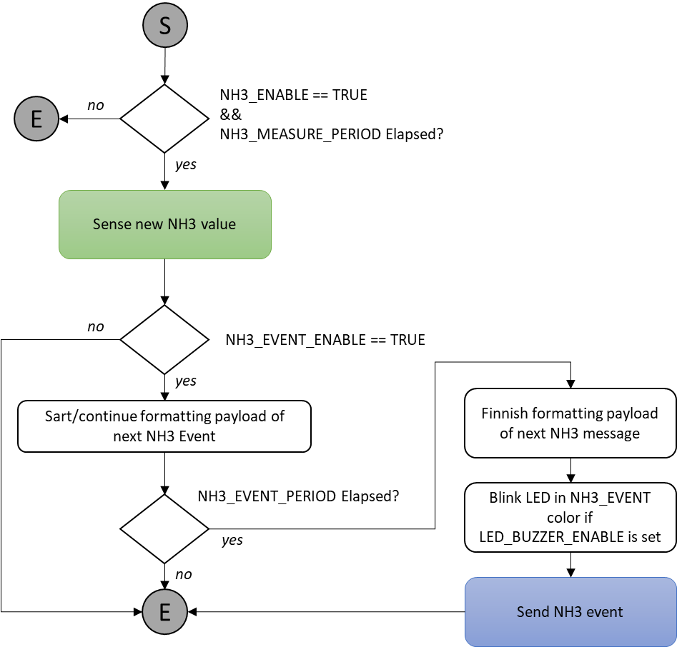
NH3 SENSING and EVENT
The NH3 sensing is enabled thanks to the NH3_ENABLE flag.
The NH3 event is enabled thanks to the NH3_EVENT_ENABLE flag.
New NH3 values are taken every NH3_MEASURE_PERIOD.
NH3 event is prepared every NH3_EVENT_PERIOD. Before sending the event, all statistics (minimum, average and
maximum for NH3 levels) are computed since the last NH3 event.
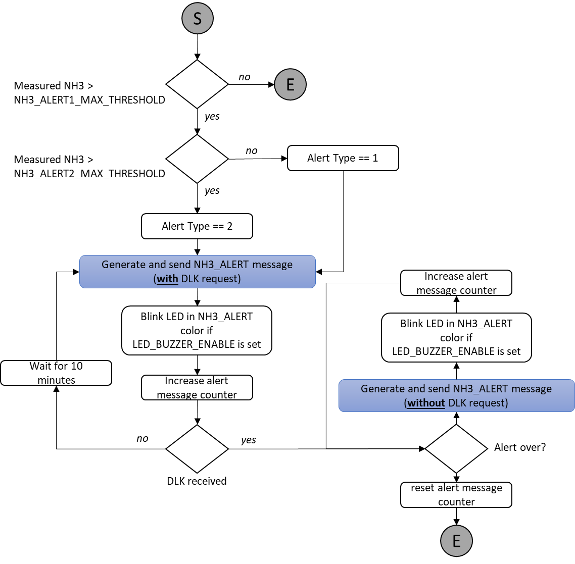
NH3 ALERT
The NH3 alert feature is enabled thanks to the NH3_ALERT_ENABLE flag.
The NH3 sensing check against NH3_ALERT1_MAX_THRESHOLD and NH3_ALERT2_MAX_THRESHOLD, is done anytime a
NH3 measurement is performed.
If the check reports that the measured level is above NH3_ALERT1_MAX_THRESHOLD or
NH3_ALERT2_MAX_THRESHOLD, an ALERT procedure will start. The NH3 measured value will be recorded during the
alert as well as the alert duration.
The ALERT message will be sent right after the alert is detected with a DLK request.
The message will be sent again until a DLK is received every 10 minutes and until the level goes back to a normal
level.
After a DLK is received, the device will keep sending Alert message every 10 minutes until the alert is over.
During the ALERT procedure, all other Sigfox events are cancelled. Only NH3 measurements is performed and BLE
advertising are maintained.
Sigfox Normal mode
6.3.3.2 Payload fields
6.3.3.3 Description
6.3.3.4 Frames
6.3.3.5 Flowchart


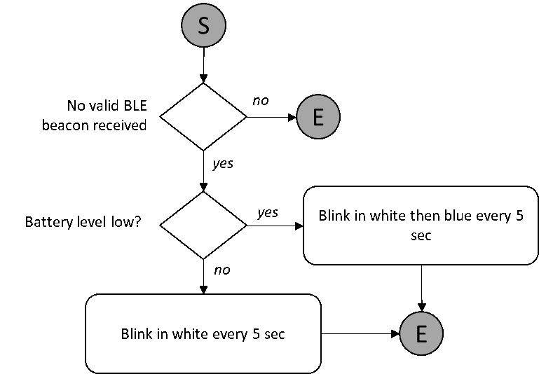
The light indicator is always in RF listening mode and searching for a beacon signal from the sensor it is attached to.
The indicator device will be able to identify the beacon signal transmitted by the NH3 sensor it is attached to and only
consider the beacon signal from that specific sensor.
Some simple synchronization mechanisms will be implemented in order to minimize the power consumption of the
receiver to an acceptable level.
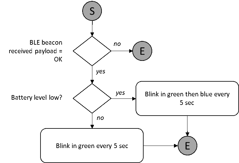
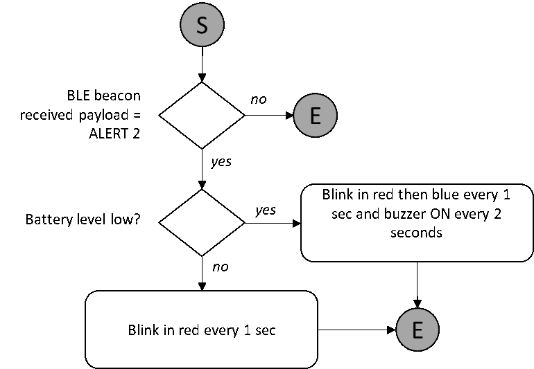
Depending on the beacon received, the indicator device will have the behavior described in the following flowcharts:
No Signal:
6.4 Light and sound indicator


Not used
6
Not used
7
Not used
8
Not used
9
Not used
10
Not used
11
Not used
12
Not used
13
Not used
14
Not used
15
Category
Parameter
Description
Possible values
Default value
Length
(in bits)
DEVICE
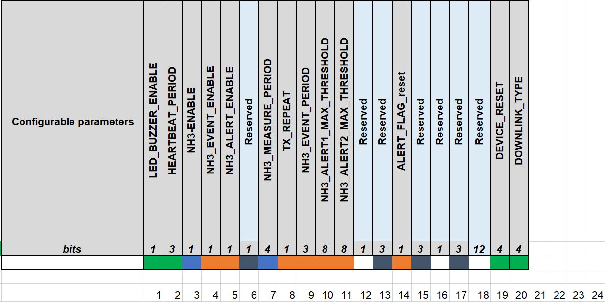
LED_BUZZER_ENABLE
Flag to enable/disable
LED and Buzzer
interactions for action
not triggered by the
button.
0b0 = false, LEDs are
OFF
0b1 = true, LEDs are
ON
0b0 = false
1
DEVICE
DEVICE_RESET
Once this parameter
is set, the device
shall restart once
after having received
the DL.
0b1010 = 0xA =
Force device reset
others = do nothing
others = do nothing
4
DEVICE
TX_REPEAT
Number of Sigfox
frames
0b0 = 1 frames
0b1 = 3 frames
0b0 = 1 frames
1
HEARTBEAT
HEARTBEAT_PERIOD
Period of time to send
HEARTBEAT event
0b000 = every 1h
0b001 = every 6h
0b010 = every 12h
0b011 = every 24h (1
day)
0b100 = every 48h (2
day)
0b101 = every 72h (3
day)
0b110 = every 120h
(5 day)
0b111 = every 240h
(10 day)
0b100= every 48h (2
days)
3
NH3
NH3_ENABLE
Enable NH3 sensing
0b0 = false, NH3
sensing is disabled
0b1 = true, NH3
sensing is enabled
0b1 = true
1
NH3
NH3_MEASURE_PERIOD
Interval of time
between two
consecutive NH3
values are acquired
0b0000 = every 1s
0b0001 = every 2s
0b0010 = every 5s
0b0011 = every 10s
0b0100 = every 20s
0b0101 = every 30s
0b0110 = every 1min
0b0111 = every 2min
0b1000 = every 5min
0b1001 = every
10min
0b1010 = every
20min
0b1011 = every
30min
0b1100 = every 1h
0b1101 = every 2h
0b1110 = every 3h
0b1111 = every 6h
0b0010 = every 5s
4
6.6 Configuration Parameters

NH3
NH3_EVENT_ENABLE
Enable NH3 event
0b0 = false, NH3
event is disabled
0b1 = true, NH3
event is enabled
0b1 = true
1
NH3
NH3_EVENT_PERIOD
Interval of time
between two
consecutive NH3
events
0b000 = every
10min
0b001 = every
30min
0b010 = every 1h
0b011 = every 2h
0b100 = every 3h
0b101 = every 6h
0b110 = every 12h
0b111 = every 24h
0b010 = every 1h
3
NH3
NH3_ALERT ENABLE
Enable NH3_ALERT
event
0b0 = false, NH3
ALERT feature is
disabled
0b1 = true, NH3
ALERT feature is
enabled
0b0 = false, NH3
ALERT feature is
disabled
1
NH3
NH3_ALERT1_MAX_THRESHOLD
Threshold #1 on the
temperature to trig a
NH3_ALERT event
8-bit unsigned integer
Formula: (8-
bit_NH3ppm*2)=
real_NH3_level_in_ppm
Range: 0 to 100ppm
Accuracy: 0.5ppm
Example:
0b01110100 = 0x74
= 116 => (116 / 2) =
58ppm
0b00001010 = 5ppm
8
NH3
NH3_ALERT2_MAX_THRESHOLD
Threshold #2on the
temperature to trig a
NH3_ALERT event
8-bit unsigned integer
Formula: (8-
bit_NH3ppm*2)=
real_NH3_level_in_ppm
Range: 0 to 100ppm
Accuracy: 0.5ppm
Example:
0b01110100 = 0x74
= 116 => (116 / 2) =
58ppm
0b00010100 =
10ppm
8
NH3
ALERT_FLAG_reset
Flag to reset the BLE
broadcast mechanism
and set it back to
normal.
0b1010 = 0xA =
leave BLE alert mode
others = do nothing
others = do nothing
1
The folllowing is the format of payload data will be sent to Sigfox server.
Category
Data name
Description
Encoding or Possible
values
Length
(in bits)
DEVICE
EVENT_ID
Unique ID identifying the
device event
4-bit unsigned integer
Possible values: As defined
in Event ID tab
4
DEVICE
LATEST_SIGFOX_DOWNLINK
Latest received and valid
sigfox downlink frame
64-bit encoded field
See Sigfox Downlink tab
64
DEVICE
HW_VERSION
Indicate HW version
4-bit unsigned integer
HW_VERSION =
HW_VERSION value in
EEPROM set in production
if Value unknown, default
value will be 0
4
DEVICE
FW_VERSION
indicate FW version
8-bit unsigned integer
Refer to FW release note
8
NH3
NH3
NH3 level of the
surrounding environment
of the device
16-bit unsigned integer
Formula: (16-
bit_NH3ppm/100)=
real_NH3_level_in_ppm
Range: 0 to 100ppm
Accuracy: 0.01ppm
Example: 0x16B7 = 5815
=> (5815 / 100) =
58.15ppm
16
Type
ALERT_TYPE
Type of alert
2-bit unsigned integer
0b0 = Not used
0b1 = Alert type 1
0b10 = Alert type 2
0b11 = Not used
2
6.7 Payload Data
6.7.1 Payload Fields

TIME
ALERT_DURATION
Alert duration in hours
8-bit unsigned integer
Formula: 8-
bit_Alert_duration =
real_TempAlert_duration_in_hours
Range: 0 to 255 hours
Accuracy: 1 hour
Example: 0b00100000 =
0x20 = 32 => 32 hours
8
Tentative
TENTATIVE
Tentative number
8-bit unsigned integer
Formula: (8-bit_Tentativve
+1)= real_tentative #
Range: 1 to 256
Accuracy: 1
Example: 0b00000111 =
0x7=7=> 7+1
=>tentative # 8
8
Size
Event Type
EVENT_ID
HW_VERSION
FW_VERSION
CURRENT
CONFIGURATION
10.0
bits
4
4
8
64
Payload data format
EVENT_ID
HW_VERSION
FW_VERSION
LATEST_SIGFOX_
DOWNLINK
START_UP
yes
yes
yes
yes
Event Type
EVENT_ID
HW_VERSION
FW_VERSION
CURRENT
CONFIGURATION
10.0
bits
4
4
8
64
Payload data format
EVENT_ID
HW_VERSION
FW_VERSION
LATEST_SIGFOX_
DOWNLINK
HEARTBEAT
yes
yes
yes
yes
Event Type
EVENT_ID
HW_VERSION
FW_VERSION
CURRENT
CONFIGURATION
10.0
bits
4
4
8
64
Payload data format
EVENT_ID
HW_VERSION
FW_VERSION
LATEST_SIGFOX_
DOWNLINK
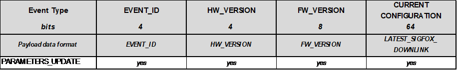
PARAMETERS_UPDATE
yes
yes
yes
yes
Event Type
EVENT_ID
HW_NH3_ERROR
RESERVED
NH3
3.0
bits
4
1
3
16
Payload data format
EVENT_ID
HW_NH3_ERROR
-
NH3
NH3_FORCE_DATA
yes
yes
zeros
yes
Event Type
EVENT_ID
HW_NH3_ERROR
RESERVED
NH3
MIN_NH3
AVG_NH3
MAX_NH3
6.7.2 Sigfox Uplink Frame Format

9.0
bits
4
1
3
16
16
16
16
Payload data
format
EVENT_ID
HW_NH3_ERROR
-
NH3
NH3
NH3
NH3
NH3
yes
yes
zeros
yes
yes
yes
yes
Event Type
EVENT_ID
HW_NH3_ERROR
RESERVED
ALERT_TYPE
EXTREME_NH3
ALERT_
DURATION
TENTATIVE
5.0
bits
4
1
1
2
16
8
8
Payload data
format
EVENT_ID
HW_NH3_ERROR
-
ALERT_TYPE
NH3
ALERT_
DURATION
TENTATIVE
NH3_ALERT
yes
yes
zeros
yes
yes
yes
yes
User can set the down link data in Sigfox back-end system in advance, whenever the Sigfox node connected to base
stations and with downlink waiting is enable at that time (one time in 6 hours), the downlink data will be loaded to
Sigfox node.
The downlink data can be any configuration parameter.
Downlink Frame Format:
Downlink type= 0b0000
6.7.3 Sigfox Downlink Frame Format.
The Sigfox node is only able to receive max 04 downlinks a day, each downlink will be waiting in every 06 hours.
Please pay attention when send downlink data. If there was a mistake in sending wrong data, it would
cause the Sigfox node not working properly and user need to configure it by offline cable!!!
For more details, you can download the file HERE
This manual suits for next models
2
Table of contents
Other daviteq Accessories manuals

daviteq
daviteq A420-FCL User manual

daviteq
daviteq WS433-AC User manual

daviteq
daviteq CAP10G User manual

daviteq
daviteq WS433-O2 User manual

daviteq
daviteq WSLRW-AG Series User manual

daviteq
daviteq LoRaWAN User manual

daviteq
daviteq WSSFC-AC User manual

daviteq
daviteq CAP10 User manual

daviteq
daviteq WS433-TAG User manual

daviteq
daviteq WS433-DI User manual


Popular Accessories manuals by other brands


Outmark
Outmark CROOZER 10000 user manual

Wenglor
Wenglor OPT1500 operating instructions

Endress+Hauser
Endress+Hauser Tophit CPS471 technical information

tomado
tomado TEB1502W instruction manual

Endress+Hauser
Endress+Hauser Turbimax CUS51D operating instructions

Linear
Linear HCI+2 installation instructions


