daviteq WSSFC-ULA-01 User manual
Thank you very much for choosing Daviteq Wireless Sensors. We are the leading wireless sensor manufacturer in the
World. We have a wide range of wireless sensors which support different connectivity like LoRaWAN, Sigfox, Sub-GHz,
NB-IoT...Please find out more information at this link.
This manual is applied to the following products
Item code
HW Version
Firmware Version
Remarks
WSSFC-ULA-01
2
2
Information Changes in this version v.s previous version
Item
Changes
Changed by
Changed Date
Approved by
Approved Date
1
Initial version
D.Q.Tuan
01-08-2022
N.V.Loc
24-08-2022
To use this product, please refer step by step to the below instructions.
Operating Principle
Uplink Payload
Battery
Connect to Sigfox Network
Installation
Troubleshooting
Configuration
Calibration
Specification
Warranty and Support
WSSFC-ULA is a Sigfox-Ready sensor with an integrated ultrasonic level sensor that can measure the waste level in the
trash bin. It can be installed in the trash bin with heights from 45 cm to 450 cm.
Manual for Sigfox-Ready
Ultrasonic Level Sensor for Trash
bin - WSSFC-ULA | FW2
1. Quick Guide
Reading time: 10 minutes
Finish this part so you can understand and put the sensor in operation with the default configuration from the
factory.
1.1 What is the Sigfox-Ready Ultrasonic Level Sensor for Trash
bin and its principle of operation?

It is battery-operated and able to connect to any Sigfox network in the World. It supports all frequency zones such as
RC1, RC2, RC3c, RC4, RC5, RC6, and RC7.
For the principle operation of the ULA Ultrasonic level sensor, please refer to this link.
Please refer to this link for typical applications.
The device will send uplink messages in the following cases:
Case 1: After power-up in the 60s, the device will send the first message called START_UP. The payload will tell
the user the HW version, FW version, and current configuration of the device;
Case 2: Then, in every interval time (pre-configured), for example, 30 minutes, it will send the message called
CYCLIC_DATA. The payload will tell the user the following data like measured value (Distance and Level), battery
level, alarm status...
Case 3: If the Alarm function was enabled (in the configuration of the sensor), if the measured value passed the
threshold, it will send the uplink message immediately. This message is called ALARM. The payload also tells the
user the data like measured value (distance and level), battery level, alarm status...
Case 4: The HEART_BEAT uplink message will be sent once a day (the default setting can be changed in
configuration) to allow the Sigfox back-end system can send the downlink message for changing the
configuration of the sensor. Please refer to the downlink section for more details. The uplink payload will tell the
user the HW version, FW version, and current configuration of the device;
Case 5: During commissioning, testing, or calibration sensor, the user can force the device to send the uplink
message to get the data immediately. This message is called FORCE_DATA. The payload will provide data like
distance from the sensor to waste, waste level, battery level, alarm status... It can be forced by applying the
magnet key on the reed switch in 1s;
Case 6: If users want to change the configuration immediately, they don't need to wait up to 1 day for the
HEART_BEAT message; instead they can force the device to send a special uplink message so that the device can
get the new downlink message. This uplink message is named PARAMETERS_UPDATE. It can be forced by
applying the magnet key in more than 5s.
The sensor was pre-configured at the factory with default values for configuration parameters that meet the most use
cases. However, depending on the specific use case, the customer can adjust those parameters. Please refer to
section 3.2 for more details.
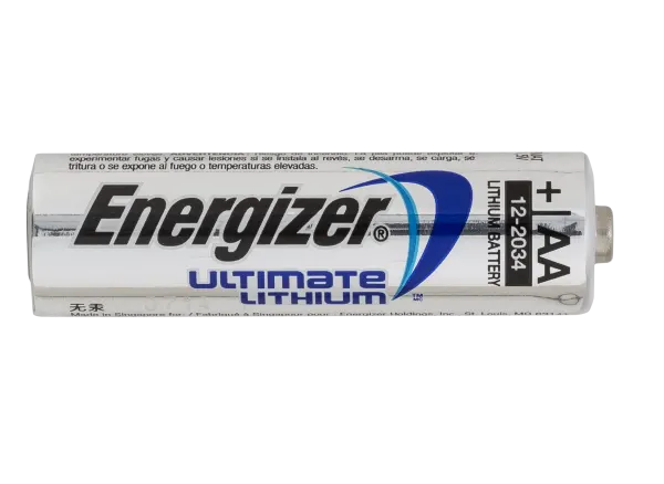
The sensor is powered by 2 x AA 1.5V batteries for many years of operation. We recommend using Energizer L91
battery which is very popular and high performance. This battery has a capacity of up to 3500mAh with a working
temperature range from -40 to +60 oC. The instruction for installing the batteries is in this link.
For Battery life estimation, please refer to this link.
1.1.1 What are the typical applications of this sensor?
1.1.2 When does the device send uplink messages?
To change the cycle of data sending, you can change the value of the parameter: CYCLIC_DATA_PERIOD (default
is 1800 seconds).
The alarm thresholds can be changed via downlink or offline tools.
1.1.3 The important configuration parameters
1.1.4 What kind of battery is used for this sensor?
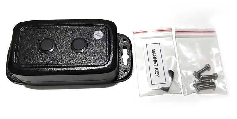
1.2 What's in the package?
The package includes:
01 x Main device
01 x Magnet key
01 x set of stainless steel bolts and nuts

With the default configuration, the device can quickly connect to the Sigfox Network by the following steps.
Device ID
Get Devive ID on the device nameplate
Device PAC
Get Devive PAC on the device nameplate
Please refer to this link for details
Please refer to this link for instructions on battery installation.
Please refer to section 1.4 Uplink Payload and Data Decoding for details of decoding the receiving packet to get
the measured values.
For the Uplink Payload structure, please refer to this link.
1.3 Quick Test
Step 1: Prepare the values of communication settings:
Note: All Sigfox sensors are pre-configured with the correct RC before delivery. The settings of Device ID,
Device PAC, and RC could also be read from the device memory map. Please reference section 3.2 Sensor
configuration for details.
Step 2: Add the device to Sigfox Backend
Step 3: Install the batteries to the device
After installing the battery in 60 seconds, the first data packet will be sent to the Sigfox network. After receiving
the first data packet, the time of another packet depends on the value of the parameter:
CYCLIC_DATA_PERIOD. Additionally, you can use a Magnet Key to force the device to send data instantly.
Step 4: Decode the payload of receiving package
1.4 Uplink Payload and Data Decoding
Note: Please select the right Payload document to suit the FW version of the sensor
1.5 Sensor Installation
SAFETY ATTENTION:
- ONLY REPLACE BATTERIES IN THE SAFE AREA WHERE THERE ARE NO FLAMMABLE GAS OR VAPOR

Please refer to this link for instructions.
Locate the place to mount the sensor:
The sensor must be mounted on the top of the trash bin;
The sensor surface must be facing down to the bottom of the trash bin;
Please refer below to some examples of the installation.
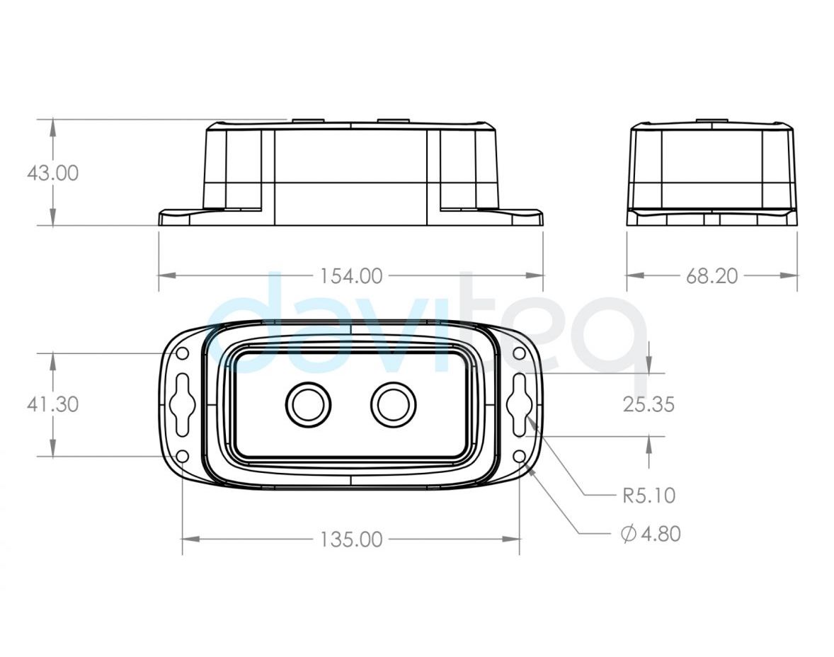
DIMENSIONS OF PRODUCT
1.5.1 Battery insertion
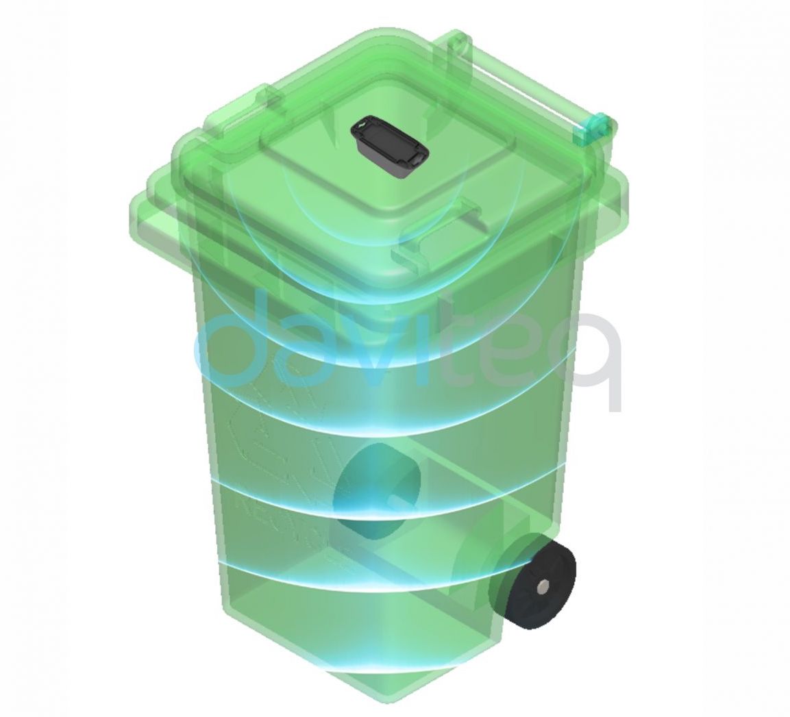
1.5.2 Mounting sensor in trash bin
Notes:
* The sensor must not be installed in a complete metallic trash bin as the RF signal cannot pass thru the metallic
wall;
* The sensor can be mounted on the movable lid. The lid will be closed all the time, it will be opened in a short
time;

MOUNTING SENSOR ON THE FIXED TOP WALL OF TRASH BIN
MOUNTING SENSOR ON THE MOVABLE LID OF TRASH BIN
MOUNTING SENSOR ON THE MOVABLE LID OF TRASH BIN
MOUNTING SENSOR ON THE OPEN-STYLE TRASH BIN
The Sigfox-Ready Ultrasonic level sensor is produced with accuracy as published in the specification of the product
and is ready to use. However, the user may need to configure the A & B factor to give the output as the actual level of
waste in the trash bin. The A & B factor will be calculated as the instructions in this link.
Problems with Sigfox communication like not receiving the packets...please refer to this link to troubleshoot
the device.
Problems with the sensor functions like not measuring or inaccurate measuring....please refer to this link to
troubleshoot the sensor part.
Maintenance works
Yes/No
Descriptions
Consumable parts replacement
No
The Sigfox-Ready Ultrasonic level sensor has
no consumable parts, so there is no need to
replace any parts.
Cleaning sensor or device
Yes
As the sensor is installed in the trash bin, it is
needed to clean the device and the transducer
surface by cleaning water with a soft
detergent. Please do not use strong detergent
or chemical solvents to clean as they can
damage the transducer surface.
Re-calibration / Re-validation
Yes
The transducer may need to be re-calibrated
when necessary. Please refer to this link for
the procedure of calibration.
To get a strong RF signal, please refer to this link.
1.5.3 Sensor calibration
2. Maintenance
2.1 Troubleshooting
2.2 Sensor maintenance

The Daviteq Sigfox-Ready Ultrasonic level sensor comprises 02 parts connected together:
- The Daviteq Sigfox-Ready wireless transmitter;
- The Daviteq Ultrasonic level transducer;
The Ultrasonic level transducer measures the average distance from the sensor surface to the waste surface in the
trash bin.
The Sigfox-Ready wireless transmitter is to read the distance value from the transducer and perform the scaling (A and
B values, during calibration). The scaled value will indicate the level of % level of waste in the trash bin.
Level = A x Distance + B
Where:
A: Constant A
B: Constant B
To understand how the ULA ultrasonic level sensor can measure the distance from the sensor to the object, please
refer to this link for a complete understanding of this measuring technique.
Below are some important configuration parameters which affect the operation of the device like battery life,
measurement accuracy, and alert threshold.
For Battery life estimation, please refer to this link.
measure_period | Default =1800s
This is the time period for the wireless transmitter to wake up and take the measurement from the transducer.
The default value is 1800s. Users can reduce this value, but smaller value, shorter battery life!
cyclic_data_period | Default = 1800s
Interval time to send an uplink message regardless of any conditions
sensor_boot_time | Default = 500mS
This value will affect the measurement accuracy. DO NOT change this value!
num_of_sample | Default = 30
The higher value, the more filtering. This filtering can eliminate the errors caused by the un-uniformed surface of
the waste and/or the moving of the lid. This value will affect the measurement accuracy. DO NOT change this
value!
Those configuration parameters can be changed by downlink or offline tools. For more other configuration parameters,
please refer to the next section.
Sensor configuration can be configured in 02 methods:
Method 1: Configuring via Downlink message. Please find the instructions in this link, but please take note of
the FW version of the Document.
Method 2: Configuring via off-line cable.
Some parameters are read-only, and some are read and writeable.
3. Advanced Guide
3.1 Operating principle of the Sigfox-Ready Ultrasonic level
sensor
3.1.1 Operating principle of the complete device
Note: the minimum distance that the transducer can detect is 3cm, it is called the blind zone of the sensor.
3.1.2 Operating principle of Ultrasonic level sensor ULA
3.1.3 Some important configuration parameters
3.2 Sensor Configuration
3.2.1 How to configure the Sigfox-Ready Ultrasonic level sensor?
3.2.2 What parameters of the device are configured?

To read the parameters, use the off-line cable as above instruction.
Via uplink message, users can read only one parameter, which is the CURRENT_CONFIGURATION.
Below tables are the lists of the parameters of the device.
Read-only Parameter Table
Modbus
Register
(Decimal)
Modbus
Register
(Hex)
Function
Code (Read)
No. of
Registers
Description
Range
Format
Property
Comment
2
2
3
4
FW_VERSION
string
Read
6
6
3
2
HW_VERSION
string
Read
8
8
3
2
DEVICE_ID
hex
Read
Product ID
10
A
3
4
DEVICE_PAC
hex
Read
Product PAC
14
E
3
1
SENSOR_TYPE
1-255
uint16
Read
Sensor or
Input Type
Read/Write Parameter Table
Modbus
Register
(Decimal)
Modbus
Register
(Hex)
Function
Code
(Read)
Function
Code
(Write)
No. of
Registers
Description
Range
Default
Format
Property
Comment
270
10E
3
16
4
CURRENT_CONFIGURATION
hex
Read/Write
Check the
Payload Document
section:
5.
Payload
for
downlink
message
for more
information
274
112
3
16
1
SERVER_CONFIG
uint16
Read/Write
0: Send to
Sigfox
Network
1: Send to
Dongle
276
114
3
16
1
RADIO_CONFIG
1-4
4
uint16
Read/Write
RC zones
selection
1, 2 , 3, 4
is RC1,
RC2,
RC3s, RC4
277
115
3
16
1
TX_POWER
20
int16
Read/Write
RF Tx
power
278
116
3
16
2
CONSTANT_A
1
float
Read/Write
Constant a
for scaling
measured
value
280
118
3
16
2
CONSTANT_B
0
float
Read/Write
Constant b
for scaling
measured
value
282
11A
3
16
2
HIGH_CUT
1E+09
float
Read/Write
High cut
value for
the
calculated
value
284
11C
3
16
2
LOW_CUT
0,5
float
Read/Write
Low cut
value for
the
calculated
value
286
11E
3
16
2
SENSOR_BOOT_TIME
500
uint32
Read/Write
Boot time
of
sensor/input,
in ms
306
132
3
16
1
NUM_OF_SAMPLE
30
uint16
Read/Write
A number
of samples
for
filtering
function.
The higher
value, the
more
filtering
Please refer to this link.
Please refer to the detailed specifications in this link.
For warranty terms and support procedures, please refer to this link.
Use-cases:
Case studies:
White-papers:
END.
Revision #20
Created Wed, Aug 24, 2022 2:40 PM by Lộc Vĩnh Nguyễn
Updated Thu, Aug 25, 2022 9:18 AM by Lộc Vĩnh Nguyễn
3.3 Calibration for Sigfox-Ready Ultrasonic Level Sensor
4. Product specification
5. Warranty and Support
6. References
Table of contents
Other daviteq Accessories manuals

daviteq
daviteq WSLRW-AG Series User manual

daviteq
daviteq WS433-O2 User manual

daviteq
daviteq WSSFCB-NH3 User manual

daviteq
daviteq CAP10 User manual

daviteq
daviteq WS433-DI User manual

daviteq
daviteq WS433-TAG User manual

daviteq
daviteq WS433-M12F-ATE User manual

daviteq
daviteq WSSFC-G4F-NH3-8-01 User manual

daviteq
daviteq A420-FCL User manual

daviteq
daviteq WS433-AC User manual


.png)