daviteq WSLRW-AG Series User manual

Thank you very much for choosing Daviteq Wireless Sensors. We are the leading wireless sensor manufacturer in the
World. We have a wide range of wireless sensors which support different connectivity like LoRaWAN, Sigfox, Sub-GHz,
NB-IoT...Please find out more information at this link.
This manual is applied to the following products
Item code
HW Version
Firmware Version
Remarks
WSLRW-AG-...
1
2
Information Changes in this version v.s previous version
Item
Changes
Changed by
Changed Date
Approved by
Approved Date
2
Improve accuracy and
resolution on FW 2
P.N.Diep
07-09-2022
N.V.Loc
07-09-2022
1
Initial version FW 1
P.N.Diep
01-06-2022
N.V.Loc
02-06-2022
To use this product, please refer step by step to the below instructions.
Operating Principle
Uplink Payload
Battery
Connect to the LoRaWAN Gateway
Installation
Troubleshooting
Configuration
Calibration
Specification
Warranty and Support
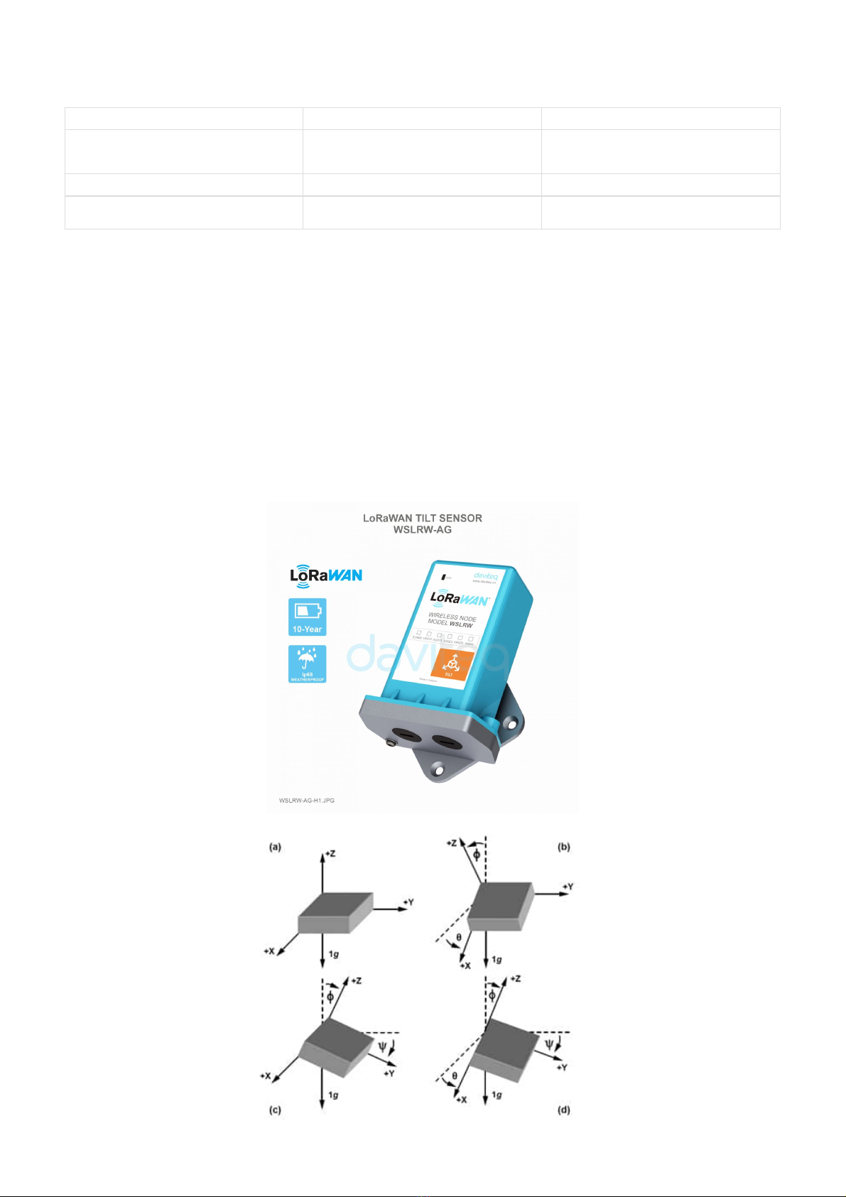
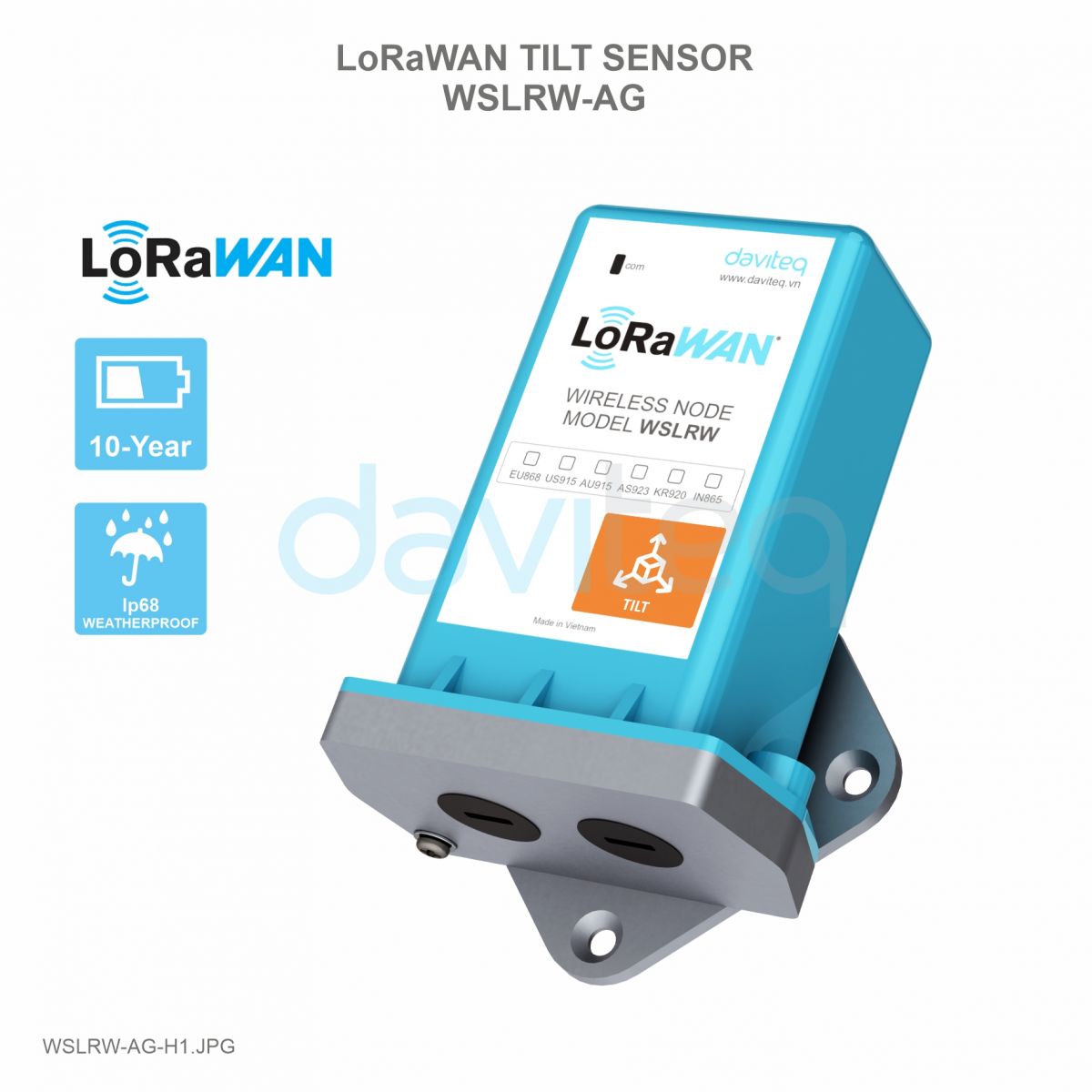
WSLRW-AG is a LoRaWAN Tilt Sensor that can measure 3 tilt angles X, Y, and Z of any object such as a Tower, Building,
Manual for LoRaWAN AG Tilt Angle
Sensor - WSLRW-AG | FW 2
1. Quick Guide
Reading time: 10 minutes
Finish this part so you can understand and put the sensor in operation with the default configuration from the
factory.
1.1 What is the LoRaWAN AG Tilt Sensor and its principle of
operation?

Tree, Electricity Tower, Telecom Tower, Bridges... The Tilt sensor utilizes the combination of an
advanced Accelerometer and Gyro meter to deliver high accuracy and stable measurement of the Tilt angle of 03 axis
X, Y, and Z. With Ultra-low Power design and smart firmware allows the sensor can last up to 10 years with 02 x AA-
type battery (depends on configuration). The sensor will transmit data in kilo-meters distance to the LoRaWAN
gateway, any brand on the market.
Please refer to this link for the AG Tilt Sensor's principle operation.
Please refer to this link for typical applications.
The device will send uplink messages in the following cases:
Case 1: After power-up in the 60s, the device will send the first message called START_UP. The payload will tell
the user the HW version, FW version, and current configuration of the device;
Case 2: Then, in every interval time (pre-configured), for example, 10 minutes, it will send the message called
CYCLIC_DATA. The payload will tell the user the following data like measured values, battery level, alarm status...
Case 3: During commissioning, testing, or calibration sensor, the user can force the device to send the uplink
message to get the data immediately. This message is called FORCE_DATA. The payload will provide data like
raw measured value, scaled measured values, battery level, alarm status... It can be forced by applying the
magnet key on the reed switch in 1s;
Case 4: If users want to change the configuration immediately, they don't need to wait until the next cyclic data
sending message, instead they can force the device to send a special uplink message so that the device can get
the new downlink message. This uplink message is named PARAMETERS_UPDATE. It can be forced by applying
the magnet key in more than 5s.
The sensor was pre-configured at the factory with default values for configuration parameters that meet most use
cases. However, depending on the specific use case, the customer can adjust those parameters. Please refer to
section 3.2 for more details.
The sensor is powered by 2 x AA 1.5V batteries for many years of operation. We recommend using Energizer L91
battery which is very popular and high performance. This battery has a capacity of up to 3500mAh with a working
temperature range from -40 to +60 oC. The instruction for installing the batteries is in this link.
For Battery life estimation, please refer to this link.
With the default configuration, the device can be connected quickly to the Network Server by the following steps.
Frequency zone
Most of the sensor was configured the frequency zone to suit customer
application before delivery
DevEUI
Get the DevEUI on the product nameplate
1.1.1 What are the typical applications of this sensor?
1.1.2 When does the device send uplink messages?
To change the cycle of data sending, you can change the value of the parameter: CYCLIC_DATA_PERIOD (default
is 600 seconds).
1.1.3 The important configuration parameters
1.1.4 What kind of battery is used for this sensor?
1.2 What's in the package?
The package includes:
01 x Main device
01 x Magnet key
01 x Wall mounting bracket and screws
1.3 Quick Test for LoRaWAN Sensor
Step 1: Prepare the values of communication settings:

AppEUI
Default value: 010203040506070809
AppKey
Default value: 0102030405060708090A0B0C0D0E0F10
Activation Mode
OTAA with local join server
Network Mode
Public
LoraWAN Protocol version
1.0.3
Class
A
Input the above settings on your device registration page of the network server.
Please visit this link to get the instructions for adding the LoRaWAN sensors to some common network servers such as
Actility, TTN...
Refer to this link for details.
Please refer to section 1.4 Uplink Payload and Data Decoding for details of decoding the receiving packet.
For the Uplink Payload structure, please refer to this link.
Note: If the above settings do not match your network server/application, please refer to section 3.2 Sensor
configuration to change the settings
Step 2: Register the device on the LoRaWAN network server.
Note: Different network server software will have different device registration processes. Please refer to the
manual of the network server software used for more details.
Step 3: Install the batteries to the device
After installing the battery in 60 seconds, the first data packet will be sent to the LoRaWAN gateway. After
receiving the first data packet, the time of another packet depends on the value of the parameter:
cycle_send_data. Additionally, you can use a Magnet Key to force the device to send data instantly.
Step 4: Decode the payload of receiving package
1.4 Uplink Payload and Data Decoding
Note: Please select the right Payload document to suit the FW version of the sensor
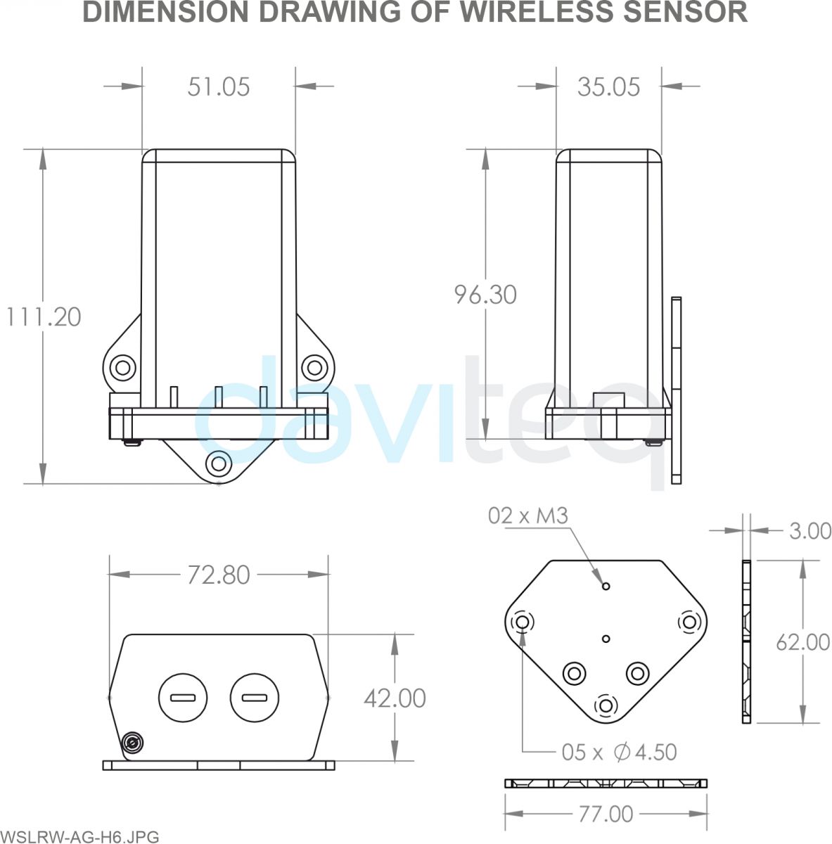
1.5 Sensor Installation
1.5.1 Dimension drawings
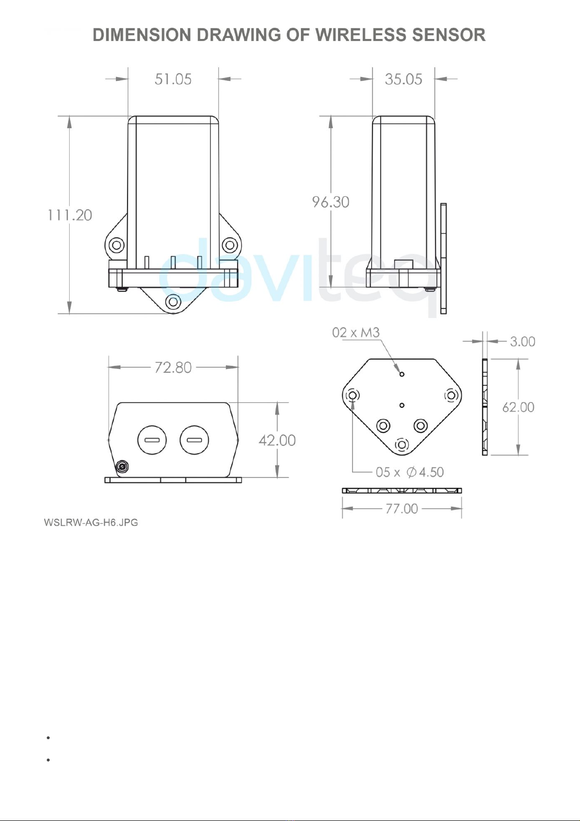
Please follow the instructions in this link.
The LoRaWAN AG Tilt sensor is pre-calibrated at the factory. There is no need to re-calibrate it at the field.
Please follow this link.
Problems with LoRaWAN communication like not receiving the packets...please refer to this link to
troubleshoot the device.
Problems with the sensor functions like not measuring or inaccurate measuring....please refer to this link to
troubleshoot the sensor part.
1.5.2 Battery Installation
1.5.3 Sensor calibration and configuration
1.5.4 Sensor mounting on wall or pole
2. Maintenance
2.1 Troubleshooting
Maintenance works
Yes/No
Descriptions
Consumable parts replacement
Yes
The battery is the only part need to check the
lifetime to replace. Check the battery status on
the back-end system.
Cleaning device
No
Re-calibration / Re-validation
No
No calibration is required for the wireless
transmitter.
Please refer to this link.
The Daviteq LoRaWAN AG Tilt Sensor comprises 02 parts linked internally:
- The Daviteq LoRaWAN wireless transmitter;
- The Daviteq AG tilt sensor;
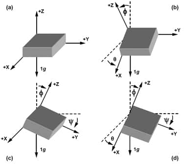
The AG Tilt sensor module measures the Acceleration of the 3-axis.
2.2 Sensor maintenance
2.2.1 Maintenance of Wireless transmitter
2.2.2 Maintenance of the AG Tilt sensor
3. Advanced Guide
3.1 Operating principle of LoRaWAN AG Tilt Sensor
3.1.1 Operating principle of the complete device

The LoRaWAN wireless transmitter is to read the measurement values from the AG sensor and performs the calculation
to deliver the desired output values, then it sends data to the gateway in the following cases:
- Case 1: when the time of the Data sending cycle is reached.
- Case 2: when the device is forced to send data by a Magnet key.
To understand how the AG Tilt sensor work, please refer to this link for a complete understanding of this measuring
technique.
Below are some important configuration parameters which affect the operation of the device.
measure_period | Default = 600s
This is the time period for the wireless transmitter to wake up and take the measurement from the sensor. The
default value is 600s. Users can reduce this value, but smaller value, shorter battery life!
cyclic_data_period | Default = 600s
Interval time to send an uplink message regardless of any conditions
Those configuration parameters can be changed by downlink or offline tools. For more other configuration parameters,
please refer to the next section.
Sensor configuration can be configured in 02 methods:
Method 1: Configuring via Downlink message. Please find the instructions in this link, but please take note of
the FW version of the Document.
Method 2: Configuring via offline cable.
Some parameters are read-only, and some are read and writeable.
To read the parameters, use the off-line cable as above instruction.
To write the parameters, use the off-line cable or downlink as above instructions.
Below tables are the lists of the parameters of the device.
Read-only Parameter Table
Modbus
Register
(Decimal)
Modbus
Register
(Hex)
Function
Code
# of
Registers
Description
Range
Default
Format
Property
Comment
0
0
3
5
device info
string
Read
Wireless
Sensor
LoRaWAN
G4 Gas
Sensor
5
5
3
4
firmware
version
1.00ddmm
string
Read
ddmm =
day / month
9
9
3
2
hardware
version
1.10
string
Read
3.1.2 Operating principle of AG Tilt sensor
3.1.3 Some important configuration parameters
3.2 Sensor Configuration
3.2.1 How to configure the LoRaWAN sensor?
Note: THE SENSOR IS ONLY ACTIVE FOR OFFLINE CONFIGURATION IN THE FIRST 60 SINCE POWER UP
BY BATTERY OR PLUGGING THE CONFIGURATION CABLE.
3.2.2 What parameters of the device are configured?

11
B
3
4
lorawan
protocol
version
01.01.00
string
Read
LoRaWAN
v1.0.3
15
F
3
6
application
version
01.03.00.00
string
Read
application
server
v1.3.0.0
21
15
3
6
mac layer
version
04.04.02.00
string
Read
mac layer
v4.4.2.0
27
1B
3
4
deviceEUI
hex
Read
End
Device's
EUI
number,
used to
register the
product on
the Network
Server by
OTAA
31
1F
3
4
Lora appEUI
hex
Read
Application
server's EUI
number is
used to
register the
product on
the Network
Server by
OTAA
35
23
3
8
Lora
appKey
hex
Read
The number
of keys
used to
create two
security
keys of the
End Device,
used to
register the
product on
the Network
Server by
OTAA

43
2B
3
8
Lora
nwkSkey
hex
Read
key number
encrypts
the
communication
command
of the MAC
layer of the
End Device,
which is
used to
register the
product on
the Network
Server by
ABP
51
33
3
8
Lora
appSkey
hex
Read
End Device
data
encryption
key
number,
used to
register the
product on
the Network
Server by
ABP
59
3B
3
2
device
address
0
uint32
Read
End Device
address
created by
the
Application
server,
used to
register the
product on
the Network
server by
ABP

61
3D
3
2
network ID
0
uint32
Read
Network
server ID
number,
used to
register the
product on
the Network
server by
ABP
63
3F
3
2
join mode
OTAA
string
Read
OTAA:
Over-the-Air
activation,
ABP:
Activation
by
Personalization
65
41
3
4
network
mode
PUBLIC
string
Read
PUBLIC,
PRIVATE
69
45
3
3
region code
AS923
string
Read
1: AS923, 2:
KR920, 3:
AU915, 4:
US915, 5:
EU868, 6:
IN865, 7:
RU864, 8:
CN779, 9:
CN470, 10:
EU433
72
48
3
4
data rate
DR2:980
string
Read
DR0:250,
DR1:440,
DR2:980,
DR3:1760,
DR4:3125,
DR5:5470
76
4C
3
3
bandwidth
BW125
string
Read
BW125,
BW250,
BW500

79
4F
3
2
spread
factor
SF10
string
Read
SF12, SF11,
SF10, SF9,
SF8, SF7
81
51
3
4
activation
of ADR
ADR OFF
string
Read
ADR ON,
ADR OFF
85
55
3
1
class
A
string
Read
103
67
3
1
sensor type
1-255
uint16
Read
1-254:
sensor
type, 255:
no sensor
Read/Write Parameter Table
Modbus
Register
(Decimal)
Modbus
Register
(Hex)
Function
Code
# of
Registers
Description
Range
Default
Format
Property
Comment
256
100
3 / 16
1
Modbus
address
1-247
1
uint16
R/W
Modbus
address of
the device
257
101
3 / 16
1
Modbus
baudrate
0-1
0
uint16
R/W
0: 9600, 1:
19200
258
102
3 / 16
1
Modbus
parity
0-2
0
uint16
R/W
0: none, 1:
odd, 2:
even
259
103
3 / 16
9
serial
number
string
R/W
(Password)
268
10C
3 / 16
2
password
for setting
uint32
R/W
(Password)
password
190577
270
10E
3 / 16
4
Lora appEUI
hex
R/W
(Password)
Application
server's EUI
number,
used to
register the
product on
the Network
Server by
OTAA
274
112
3 / 16
8
Lora
appKey
hex
R/W
(Password)
The number
of keys
used to
create two
security
keys of the
End Device,
used to
register the
product on
the Network
server by
OTAA
Note: Please check the column Property to identify which parameter requests a password for writing a new
value. In this case, the user needs to input the password (190577) into the parameter name "password for
setting" at address 268.
282
11A
3 / 16
8
Lora
nwkSkey
hex
R/W
(Password)
key number
encrypts
the
communication
command
of the MAC
layer of the
End Device,
which is
used to
register the
product on
the Network
Server by
ABP
290
122
3 / 16
8
Lora
appSkey
hex
R/W
(Password)
End Device
data
encryption
key
number,
used to
register the
product on
the Network
Server by
ABP
298
12A
3 / 16
2
device
address
uint32
R/W
(Password)
End Device
address
created by
the
Application
server,
used to
register the
product on
the Network
server by
ABP
300
12C
3 / 16
2
network ID
uint32
R/W
(Password)
Network
server ID
number,
used to
register the
product on
the Network
server by
ABP
302
12E
3 / 16
1
activation
mode (join
mode)
0-1
1
uint16
R/W
(Password)
1: OTAA
(Over-the-
Air
Activation),
0: ABP
(Activation
by
Personalization)
303
12F
3/16
1
downlink
flag
0-1
1
unint16
R/W
1: Enable
0: Disable
304
130
3 / 16
1
application
port
1-255
1
uint16
R/W
(Password)
Port 224 is
reserved
for
certification
305
131
3/16
1
network
mode
0-1
1
uint16
R/W
1: Public, 0:
Private
317
13D
3 / 16
1
region
1-7
1
uint16
Read/Write(Password)
1: AS923-1,
2: KR920,
3: AU915,
4: US915,
5: EU868,
6: IN865, 7:
RU864, 8:
AS923-2, 9:
AS923-3,
10: AS923-
1 Japan
318
13E
3 / 16
1
data rate
7
uint16
R/W
(Password)
0: 250 bps,
1: 440 bps,
2: 980 bps,
3: 1760
bps, 4:
3125 bps,
5: 5470 bps
319
13F
3 / 16
1
tx power
2-20
16
uint16
R/W
(Password)
tx power:
2,4,6,8,10,12,14,16,18,20

320
140
3 / 16
1
adaptative
data rate
0-1
0
uint16
R/W
(Password)
Automatically
adjust data
rate, 0:
disable, 1:
enable
330
14A
3/16
4
current_configuration
hex
R/W
current
configuration
code of the
device
Please refer to this link.
Please refer to the detailed specifications in this link.
For warranty terms and support procedures, please refer to this link.
Use-cases:
Case studies:
White-papers:
END.
Revision #3
Created Tue, Sep 20, 2022 1:36 PM by Lộc Vĩnh Nguyễn
Updated Tue, Sep 20, 2022 2:15 PM by Lộc Vĩnh Nguyễn
3.3 Calibration or commissioning for AG Tilt sensor
4. Product specification
5. Warranty and Support
6. References
Table of contents
Other daviteq Accessories manuals

daviteq
daviteq WS433-O2 User manual

daviteq
daviteq WS433-M12F-ATE User manual

daviteq
daviteq WS433-AC User manual

daviteq
daviteq WSSFCB-NH3 User manual

daviteq
daviteq WSSFC-ULA-01 User manual

daviteq
daviteq WS433-TAG User manual

daviteq
daviteq CAP10 User manual

daviteq
daviteq LoRaWAN User manual

daviteq
daviteq A420-FCL User manual

daviteq
daviteq WS433-DI User manual


.png)