daviteq WSSFC-V1A-025 User manual

Thank you very much for choosing Daviteq Wireless Sensors. We are the leading wireless sensor manufacturer in the
World. We have a wide range of wireless sensors which support different connectivity like LoRaWAN, Sigfox, Sub-GHz,
NB-IoT...Please find out more information at this link.
This manual is applied to the following products
Item code
HW Version
Firmware Version
Remarks
WSSFC-V1A-025
2
Product Features
Connectivity Type
Sigfox
Product Type
2 parts
Mounting Type
Direct process mounting for sensor, wall mount for transmitter
Powered by
2 x AA batteries 1.5V
Information Changes in this version v.s previous version
Item
Changes
Changed by
Changed Date
Approved by
Approved Date
1
Initial version
D.Q.Tuan
29-08-2022
N.V.Loc
05-09-2022
To use this product, please refer step by step to the below instructions.
Operating Principle
Uplink Payload
Battery
Connect to Sigfox Network
Installation
Troubleshooting
Configuration
Calibration
Specification
Warranty and Support
Manual for Sigfox-Ready Single-
Axis Vibration Sensor - WSSFC-
V1A | FW2
1. Quick Guide
Reading time: 10 minutes

WSSFC-V1A is a cost-effective, single-axis vibration sensor designed for condition monitoring and preventive
maintenance applications. The piezo-electric accelerometer is available in ranges ±25g or 50g and features a flat
frequency response up to >10kHz. Its accelerometer feature a stable piezo-ceramic crystal in shear mode with low-
power electronics, sealed in a fully hermetic package. The Piezo Electric technology incorporated in the WSSCF-V1A
accelerometer has a proven track record for offering the reliable and long-term stable output required for condition
monitoring applications. The accelerometer is designed and qualified for machine health monitoring and has superior
Resolution, Dynamic Range, and Bandwidth to MEMS devices. Besides that, it can also measure the temperature at the
mounting point.
It is battery-operated and able to connect to any Sigfox network in the World. It supports all frequency zones such as
RC1, RC2, RC3c, RC4, RC5, RC6, and RC7.
For the principle operation of the V1A single-axis vibration sensor, please refer to this link.
Please refer to this link for typical applications.
The device will send uplink messages in the following cases:
Case 1: After power-up in the 60s, the device will send the first message called START_UP. The payload will tell
the user the HW version, FW version, and current configuration of the device;
Case 2: Then, in every interval time (pre-configured), for example, 10 minutes, it will send the message called
CYCLIC_DATA. The payload will tell the user the following data like measured values, battery level, alarm status...
Case 3: If the Alarm function was enabled (in the configuration of the sensor), if the measured value passed the
threshold, it will send the uplink message immediately. This message is called ALARM. The payload also tells the
user the data like measured values, battery level, alarm status...
Case 4: The HEART_BEAT uplink message will be sent once a day (the default setting can be changed in
configuration) to allow the Sigfox back-end system can send the downlink message for changing the
configuration of the sensor. Please refer to the downlink section for more details. The uplink payload will tell the
user the HW version, FW version, and current configuration of the device;
Case 5: During commissioning, testing, or calibration sensor, the user can force the device to send the uplink
message to get the data immediately. This message is called FORCE_DATA. The payload will provide data like
raw measured value, scaled measured value, battery level, alarm status... It can be forced by applying the
magnet key on the reed switch in 1s;
Case 6: If users want to change the configuration immediately, they don't need to wait up to 1 day for the
HEART_BEAT message, instead they can force the device to send a special uplink message so that the device can
get the new downlink message. This uplink message is named PARAMETERS_UPDATE. It can be forced by
applying the magnet key in more than 5s.
The sensor was pre-configured at the factory with default values for configuration parameters that meet most use
cases. However, depending on the specific use case, the customer can adjust those parameters. Please refer to
section 3.2 for more details.
The sensor is powered by 2 x AA 1.5V batteries for many years of operation. We do recommend using Energizer L91
battery which is very popular and high performance. This battery has a capacity of up to 3500mAh with a working
temperature range from -40 to +60 oC. The instruction for installing the batteries is in this link.
Figure 1. Battery Energizer L91
Finish this part so you can understand and put the sensor in operation with the default configuration from the
factory.
1.1 What is the Sigfox-Ready V1A Single-Axis Vibration Sensor
and its principle of operation?
1.1.1 What are the typical applications of this sensor?
1.1.2 When does the device send uplink messages?
To change the cycle of data sending, you can change the value of the parameter: CYCLIC_DATA_PERIOD (default
is 600 seconds).
The alarm thresholds can be changed via downlink or offline tools.
1.1.3 The important configuration parameters
1.1.4 What kind of battery is used for this sensor?

For Battery life estimation, please refer to this link.
Figure 2. Product package of WSSFC-V1A-025
With the default configuration, the device can be connected quickly to the Sigfox Network by the following steps.
Device ID
Get Devive ID on the device nameplate
Device PAC
Get Devive PAC on the device nameplate
Please refer to this link for details
Please refer to this link for instructions on battery installation.
Please refer to section 1.4 Uplink Payload and Data Decoding for details of decoding the receiving packet to get
the measured values.
1.2 What's in the package?
The package includes:
01 x Main device with 2m M12 cable
01 x Magnet key
01 x Wall mounting bracket and screws
01 x Vibration sensor module V1A
1.3 Quick Test
Step 1: Prepare the values of communication settings:
Note: All Sigfox sensors are pre-configured with the correct RC before delivery. The settings of Device ID,
Device PAC, and RC could also be read from the device memory map. Please reference section 3.2 Sensor
configuration for details.
Step 2: Add the device to Sigfox Backend
Step 3: Install the batteries to the device
After installing the battery in 60 seconds, the first data packet will be sent to the Sigfox network. After receiving
the first data packet, the time of another packet depends on the value of the parameter:
CYCLIC_DATA_PERIOD. Additionally, you can use a Magnet Key to force the device to send data instantly.
Step 4: Decode the payload of receiving package
1.4 Uplink Payload and Data Decoding

For the Uplink Payload structure, please refer to this link.
Figure 3. Dimensions of Sigfox Transmitter
Figure 4. Dimensions of V1A vibration sensor module
The Sigfox-Ready V1A vibration sensor combines a wireless transmitter WSSFC and a V1A vibration sensor. Therefore,
the installation will be divided into 02 parts:
INSTALLATION GUIDE FOR V1A SENSOR MODULE
INSTALLATION GUIDE FOR WIRELESS TRANSMITTER.
PLEASE SEE THE BELOW STEPS.
Mount the wireless transmitter on the wall or a pole nearby the object to monitor the vibration. The wireless
transmitter must be mounted at the minimum level of 2m from the ground for a better RF signal. To get the
strongest RF signal, please follow this link.
How to mount it with a mounting bracket? please check this guide.
Insert the batteries into the wireless transmitter and check the system to see whether the wireless transmitter
already sent the first message to the system. Please follow this link to learn how to install the batteries.
Connect the M12 cable to the V1A sensor module as below figure.
Note: Please select the right Payload document to suit the FW version of the sensor
1.5 Sensor Installation
1.5.1 Dimension drawings
1.5.2 Installation
ATTENTION:
REVERSED POLARITY OF BATTERIES IN 10 SECONDS CAN DAMAGE THE SENSOR CIRCUIT!!!
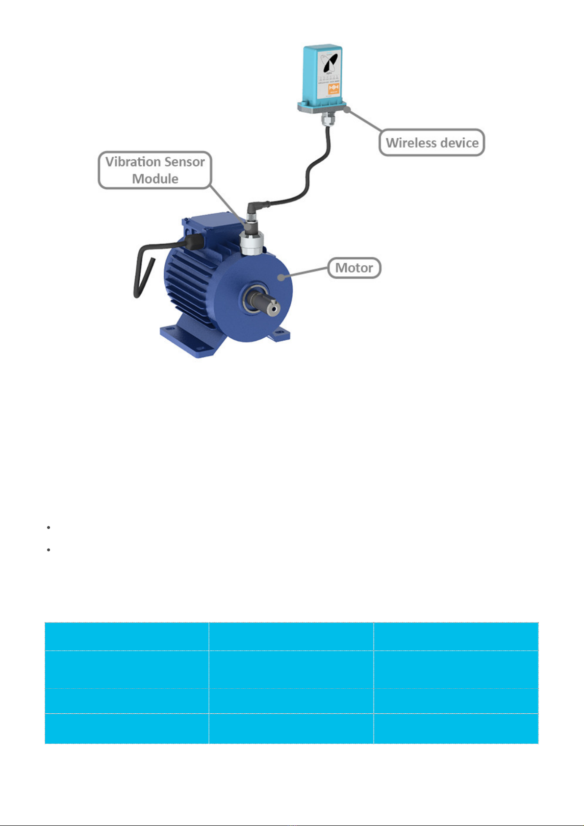
Figure 5. Complete set of WSSFC-V1A-025 vibration sensor
Please refer to this link.
Problems with Sigfox communication like not receiving the packets...please refer to this link to troubleshoot
the device.
Problems with the sensor functions like not measuring or inaccurate measuring....please refer to this link to
troubleshoot the sensor part.
Maintenance works
Yes/No
Descriptions
Consumable parts replacement
Yes
The battery is the only part need to check the
lifetime to replace. Check the battery status on
the back-end system.
Cleaning device
No
Re-calibration / Re-validation
No
No calibration is required for the wireless
transmitter.
Please refer to this link.
1.5.3 Device calibration & configuration
2. Maintenance
2.1 Troubleshooting
2.2 Device maintenance
2.2.1 Maintenance for Wireless transmitter
2.2.2 Maintenance for V1A sensor module

The Daviteq Sigfox-Ready V1A Single-axis Vibration Sensor comprises 02 parts connected together as shown below
picture.
- The Daviteq Sigfox-Ready wireless transmitter
- The Daviteq V1A vibration sensor module
Figure 6. Complete set of WSSFC-V1A-025 vibration sensor mounted on the motor
The V1A single-axis vibration sensor measures the vibration of the object.
The Sigfox-Ready wireless transmitter is to read the measurement values from the V1A sensor and performs the
scaling and calculation to deliver accurate outputs.
To understand how the V1A single-axis vibration sensor works, please refer to this link for a complete understanding
of this measuring technique.
Below are some important configuration parameters which affect the operation of the device like battery life,
measurement accuracy, and alert threshold.
For Battery life estimation, please refer to this link.
measure_period | Default = 3600s
This is the time period for the wireless transmitter to wake up and take the measurement from the transducer.
The default value is 3600s. Users can reduce this value, but smaller value, shorter battery life!
cyclic_data_period | Default = 3600s
3. Advanced Guide
3.1 Operating principle of the Sigfox-Ready V1A Single-axis
Vibration Sensor
3.1.1 Operating principle of the complete device
3.1.2 Operating principle of V1A single-axis vibration sensor
3.1.3 Some important configuration parameters

Interval time to send an uplink message regardless of any conditions
constant_A | Default = calibrated value by factory
This value will affect the measurement accuracy. DO NOT change this value!
Those configuration parameters can be changed by downlink or offline tools. For more other configuration parameters,
please refer to the next section.
Sensor configuration can be configured in 02 methods:
Method 1: Configuring via Downlink message. Please find the instructions in this link, but please take note of
the FW version of the Document.
Method 2: Configuring via offline cable.
Some parameters are read-only, and some are read and writeable.
To read the parameters, use the off-line cable as above instruction.
Via uplink message, users can read only one parameter, which is the CURRENT_CONFIGURATION.
Below tables are the lists of the parameters of the device.
Read-only Parameter Table
Modbus
Register
(Decimal)
Modbus
Register
(Hex)
Function
Code (Read)
No. of
Registers
Description
Range
Format
Property
Comment
2
2
3
4
FW_VERSION
string
Read
6
6
3
2
HW_VERSION
string
Read
8
8
3
2
DEVICE_ID
hex
Read
Product ID
10
A
3
4
DEVICE_PAC
hex
Read
Product PAC
14
E
3
1
SENSOR_TYPE
1-255
uint16
Read
Sensor or
Input Type
Read/Write Parameter Table
Modbus
Register
(Decimal)
Modbus
Register
(Hex)
Function
Code
(Read)
Function
Code
(Write)
No. of
Registers
Description
Range
Default
Format
Property
Comment
270
10E
3
16
4
CURRENT_CONFIGURATION
hex
Read/Write
Check the
Payload Document
section:
5.
Payload
for
downlink
message
for more
information
274
112
3
16
1
SERVER_CONFIG
0
uint16
Read/Write
0: Send to
Sigfox
Network
1: Send to
Dongle
276
114
3
16
1
RADIO_CONFIG
1-4
4
uint16
Read/Write
RC zones
selection
1, 2 , 3, 4
is RC1,
RC2,
RC3s, RC4
3.2 Sensor Configuration
3.2.1 How to configure the Sigfox-Ready V1A Sing-axis Vibration Sensor?
3.2.2 What parameters of the device are configured?

277
115
3
16
1
TX_POWER
20
int16
Read/Write
RF Tx
power
278
116
3
16
2
CONSTANT_A
1
float
Read/Write
Constant a
for scaling
measured
value
306
132
3
16
1
ENB_DATGRAM
1
uint16
Read/Write
bit0:
enable
datagram
0
bit1:
enable
datagram
1
bit2:
enable
datagram
2
307
133
3
16
1
TEMPERATURE_OFFSET_X10
0
int16
Read/Write
Offset
adjustment
for
measured
temperature
value
Please refer to this link.
Please refer to the detailed specifications in this link.
For warranty terms and support procedures, please refer to this link.
Use-cases:
Case studies:
White-papers:
END.
Revision #8
Created Wed, Sep 7, 2022 9:48 AM by Lộc Vĩnh Nguyễn
Updated Thu, Sep 8, 2022 10:06 AM by Phan Van Luc
3.3 Calibration for Sigfox-Ready V1A Vibration Sensor
4. Product specification
5. Warranty and Support
6. References
Table of contents
Other daviteq Accessories manuals

daviteq
daviteq A420-FCL User manual

daviteq
daviteq WS433-DI User manual

daviteq
daviteq CAP10G User manual

daviteq
daviteq CAP10 User manual

daviteq
daviteq WSSFC-ULA-01 User manual

daviteq
daviteq LoRaWAN User manual

daviteq
daviteq WS433-AC User manual

daviteq
daviteq WSLRW-AG Series User manual

daviteq
daviteq WS433-TAG User manual

daviteq
daviteq WSSFC-AC User manual


.png)
.png)
.png)
.png)
.png)