daviteq WS433-DI User manual

WS433-DI-MN-EN-01
FEB-2020
SKU
WS433-DI
HW Ver.
2.5
FW Ver.
5.0
Item Code
WS433-DI-12
Wireless Sensor with 2 channel Digital inputs with dry-contact of voltage input max 3.3VDC, Logic
detecting or Pulse counting IP67, battery AA 1.5VDC, shielded cable 0.5m length with PG9 cable
gland
HW Ver.
FW Ver.
Release Date
Functions Change
2.5
5.0
DEC-2019
Change function status or
counter by switch
Change RF data rate by
button
Wireless sensor with 2 channel digital inputs to detect logic status 0/1 OR counting pulses from proximity sensor, limit
switch, machine output, pressure switch…It is configured the operation parameters like data sending interval, health
check cycle...remotely from Globiots platform or via ModbusRTU software. The wireless module can last up to 10 years
with a single AA battery.
USER GUIDE FOR WIRELESS
SENSOR DIGITAL INPUTS WS433-
DI
This document is applied for the following products
1. Functions Change Log
2. Introduction
3. Specification

Input
2 channel Digital inputs with dry-contact or voltage input (max 3.3VDC)
Functions
M12-female, 4-pin A-coding
Electrical connection
Shielded cable 0.5m length with PG9 cable gland
Optional accessories
304SS Adapter PG9/male 1/2"NPT or PG13.5 or M20 to allow direct
mounting on Process instruments or electrical panel
Data speed
Up to 50kbps
Tranmission distance, LOS
500m
Antenna
Internal Antenna, 3 dBi
Battery
01 x AA 1.5VDC, up to 10-year operation, depends on configuration
Frequency Band
ISM 433Mhz, Sub-GHz technology from Texas Instrument, USA
Receiving Sensitivity
-110dBm at 50kbps
International Compliance
ETSI EN 300 220, EN 303 204 (Europe) FCC CFR47 Part15 (US), ARIB
STD-T108 (Japan)
Security Standard
AES-128
Operating temperature of PCB
-40oC..+60oC (with AA L91 Energizer)
Housing
Poly-carbonate, IP67
Installation method
L-type bracket SUS304 , by M4 screws or double-sided 3M tape
(included)
Product dimensions
125x30x30mm
Net weight (without battery)
< 100g
Box dimension
190x50x50mm
Gross weight
140g
4. Product Pictures


WS433-DI-12 has 02 digital inputs, there are 02 operation modes:
Digital status detector Mode;
Counter Mode.
To use Digital Status Detector mode, please turn the switch in the wireless node to the Status Detecting Mode.
Whenever the status changes from 0 to 1 or from 1 to 0, the wireless node will send data package, includes the
status of Digital input DI1 and DI2, the value can be 0 or 1.
Please retrieve the status values of DI1 and DI2 at the following addresses.
To retrieve the Toggle value, please read at the following addresses.
http://filerun.daviteq.com/wl/?id=jhA8Bk46jtMORODSOuKfEwVajKEGeSPX
Beside that, there are also other addresses hold the analytic data of DI1 and DI2:
Counter value:..
Hour counter value:...
DI1 and DI2 can work as a counter to count the Digital Pulse applied on them;
The recommended max frequency of Pulse is 1Hz. The higher frequency, the higher energy consumption, the
lower battery life;
Connect to a switch (status detector).
Connect to a button (status detector with toggle registers).
Connect to a Reed switch to detect Door opened/closed.
Connect to limit switch of equipment or Valve to detect status Run/Stop or Open/Close
Connect to auxiliary of relay or contactor to detect status of counting the status of machine, equipment
Connect to Smoke detector
Connect to Isolated AC/DC voltage detector to detect the running status of Machine, Fan, Pump...
5. Operation Principle
5.1 Digital Status Detector
5.2 Counter Mode
5.3 Applications
6. Configuration
6.1 LED Function

LED status indicator when using the button for 30 seconds after installing the battery => if not using the button, the
LED will not work.
After that, the LED will blink when sending data packet to Co-ordinator.
Use the push button to set the data transfer speed for the first 30 seconds when the battery is first installed, after 30
seconds the push button function does not work.
Press and hold the button for 2 seconds => LED blinks once => Release the button to set Data rate RF 50kbps
Press and hold the button for 5 seconds => LED blinks twice => Release the button to set Data rate RF 625bps
Press and hold the button for 10 seconds => LED blinks 3 times => Release the button to reset RF parameters
(frequency, RF output power, data rate), if held for more than 30 seconds then the button function does not
work.
Used to select the wireless sensor input is 2 channel Counter or 2 channel Status.
Configuration steps:
Step 1: Set the switch according to the label on the board as "Counter" or "Status".
Step 2: Remove the battery.
Step 3: Wait for about 10 seconds and then insert the battery.
Step 4: Read Sensor status information in the packet sent to know whether the sensor is operating in Counter
mode or Status => see file "Modbus Memmap of WR433-FW_V1.9 for WS433-FW_V5.xx.xlsx" as the following link
for more information.
http://filerun.daviteq.com/wl/?id=jhA8Bk46jtMORODSOuKfEwVajKEGeSPX
You can configure the wireless sensor with the co-ordinator by following the steps in the link below:
http://www.daviteq.com/en/manuals/books/long-range-wireless-co-ordinator-ws433-cl/page/user-guide-
for-long-range-wireless-co-ordinator-ws433-cl
Wireless Sensor Digital Inputs WS433-DI has been mounted mounting bracket.
Wireless sensor digital inputs WS433-DI utilize the ultra-low power 433Mhz RF signal to transmit/receive data with
Wireless sensor co-ordinator (WR433-).
To maximize the distance of transmission, the ideal condition is Line-of-sight (LOS) between the two modules. In real
life, there is no LOS condition. However, the two modules still communicate each other, but the distance will be
reduced significantly.
Therefore, to maximize the transmission distance, please pay attention to the following conditions:
DO NOT install the wireless module inside a complete metallic box or housing. The RF signal can not pass
through metallic wall;
This wireless module would be installed a semi-metallic box, because the RF signal can pass through the non-
metal wall/are;
The best case is to install the wireless module inside or Non-metallic box;
Some non-metallic materials: plastic, glass, wood, leather, concrete, cement…
6.2 Button Function
6.3 Switch Function
6.4 Wireless sensor configuration with co-ordinator
7. Installation
7.1 Mounting bracket installation
7.2 Installation location
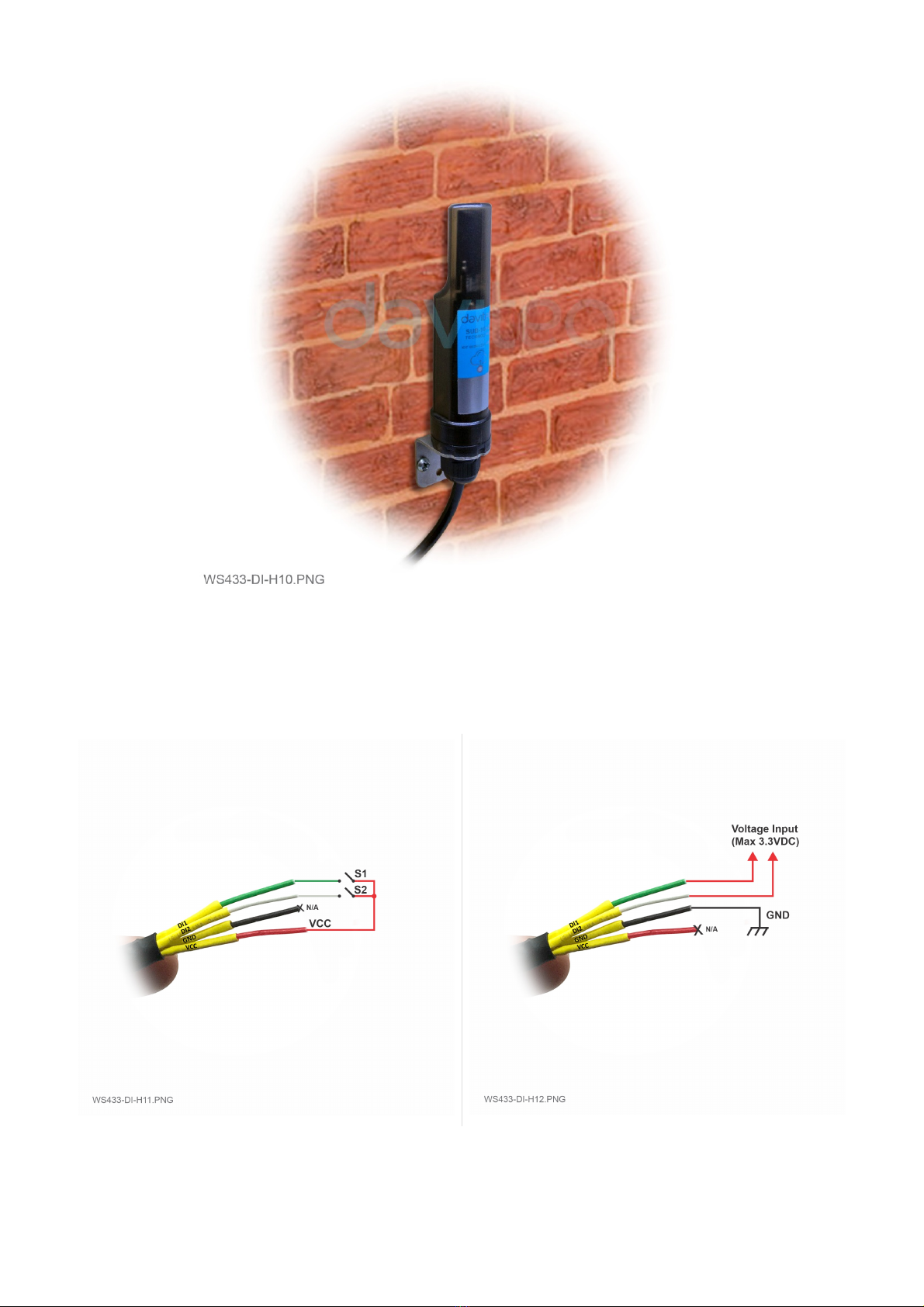
Connect DI1 and DI2 of the wireless sensor digital inputs to any dry contact (S1, S2) like relay, button, switch, … to
VCC or voltage input (max 3.3VDC) to DI1, DI2.
The wireless sensor digital inputs will detect status of the DI1 and DI2.
*Note: Please DO NOT connect VCC to any external power source more than 3.3VDC.
**Note: To change the Digital Input function to Counter, uncover the housing, find the Status switch and turn it to
Counter, take the battery out, wait 5 seconds then put it back to the sensor.
***Note: If the extension cord of WS433-DI is required, use the wire type Control Cable Cu/PVC/OS/PVC 4x0.25mm2,
Length=5m, Rohs, Shield 80% and shielding should be soldered to GND if possible.
7.3 IO Wiring & Sensor installation


No.
Phenomena
Reason
Solutions
1
The status LED of wireless sensor
doesn't light up
No power supply
Configuration function of
the LED is not correct
Check that the battery is
empty or not installed
correctly
Reconfigure the led light
function exactly as
instructed
2
Wireless sensor uses the wrong
counter or status function
Configuration of switch
function is not correct
Check that the switch is set
up correctly
3
Wireless sensor not connected to
co-ordinator
No power supply
The configuration function
of the RF data rate is
incorrect
Check that the battery is
empty or not installed
correctly
Reconfigure the RF data
rate with the button
according to the
instructions
Distributor in Malaysia
AVO Technology Sdn. Bhd.
Official Website: www.avo.com.my
No. 17, Jalan 3/23A, Taman Danau Kota, 53300 Kuala Lumpur, Wilayah
Persekutuan Kuala Lumpur, Malaysia
General : +603-4143 2288
Mobile : +012-376 7181
Fax : +603-4143 3388
Distributor in Australia and New Zealand
Templogger Pty Ltd
Tel: 1800 LOGGER
Email: contact@templogger.net
Manufacturer
Dai Viet Controls & Instrumentation Company Ltd.
No.11 Street 2G, Nam Hung Vuong Res., An Lac Ward, Binh Tan Dist., Ho Chi Minh City, Vietnam.
Tel: +84-28-6268.2523/4 (ext.122)
Email: info@daviteq.com | www.daviteq.com
Revision #40
Created Wed, Feb 5, 2020 2:35 AM by Kiệt Anh Nguyễn
Updated Thu, Mar 5, 2020 8:46 AM by Kiệt Anh Nguyễn
8. Troubleshooting
9. Support contacts
Table of contents
Other daviteq Accessories manuals

daviteq
daviteq CAP10 User manual

daviteq
daviteq CAP10G User manual

daviteq
daviteq WSSFC-AC User manual

daviteq
daviteq WS433-O2 User manual

daviteq
daviteq WSSFC-G4F-NH3-8-01 User manual

daviteq
daviteq WS433-M12F-ATE User manual

daviteq
daviteq WSSFC-V1A-025 User manual

daviteq
daviteq LoRaWAN User manual

daviteq
daviteq WSSFCB-NH3 User manual

daviteq
daviteq WS433-TAG User manual


