daviteq LoRaWAN User manual


What is LoRaWAN?

No.
Phenomena
Reason
Solutions
1
The BLUE LED does not blink
when the battery is installed
Insert the batteries in the
wrong direction
Insert the battery in the correct
way
2
The RED LED is always on
Due to noise, the peripheral
components (i2c, spi, uart, ..)
of RF module cannot be
initialized
After the 30s the node will
automatically reset. If the noise
causes the Watchdog not to
initialize, remove the battery and
wait for more than 10 seconds,
then insert the battery again
3
The RED LED blinks
continuously (10ms ON / 2s
OFF) and the Node does not
send RF. After more than 10
sending cycles, the Node will
automatically reset
· Operating frequency in
that country is prohibited
· Operating frequency in
that country is limited to Data
rate, Tx Power
· Reconfigure the allowed
frequency of operation
· Reconfigure Data rate = DR5 /
SF07, Tx Power
4
RED LED blinks continuously
(10ms ON / 2s OFF) and Node
sends RF continuously 3s /
time but no data. After more
than 10 sending cycles, the
Node will automatically reset
Node runs dummy sending
mode
=> sent by Gateway to send
Downlink packets when users
clear Uplink and Downlink
counter values on Network
Server (build-in Gateway) when
activated by ABP
Configuration enabled by OTAA
5
The RED LED flashes 10ms
ON / 10s OFF and the Node
does not send RF
Node activation by OTAA on
the Network server has not
been successful
Using Magnet-Key to force Node to
send RF continuously for 3
seconds/time
=> when activating by OTAA
successfully, the GREEN LED will
blink after sending RF
6
The node sent RF successfully
but the GREEN LED did not
blink
LED is broken
Warranty to replace LED
7
The data packet taken from
the Gateway has an incorrect
value
The data package is encrypted
Get the decoded packet on the
Application Server
8
The node sends RF and
activates by ABP, on Gateway
receives data but Application
server has no data
The application server still
stores the counter values of the
previous Uplink and Downlink
Delete the counter values of Uplink
and Downlink on the Application
server
9
The node does not send RF
and the RF module is hot
· Insert the battery in the
opposite direction
· Short circuit
Warranty or replacement
10
Node does not send RF to
Gateway according to the
alarm, LED does not blink
· The alarm configuration is
incorrect
· Running out of the number
of alarms set for the day
· Check alarm configuration
· Check the configuration for
the maximum number of alarms
per day
11
Node does not send RF to
Gateway when activated by
the magnetic switch, LED
does not blink
The magnetic switch has
malfunctioned
Read the status of the magnetic
switch via Modbus (when powering
or attaching the battery) to see if
the magnetic switch is working.
12
Node has blinked LED GREEN
when sending RF but the
Gateway or Application server
cannot receive
· LoRa module on the
Gateway is faulty
· The IP connection (4G /
WiFi / ...) on the Gateway is
faulty
· Check Gateway's LoRa status
lights on Gateway
· Check 4G / WiFi status lights
on Gateway
Troubleshooting for LoRaWAN
communication
This is the troubleshooting for the LoRaWAN sensor with FW versions listed below:

13
The value of the sensor is 0
and sensor_type = 0xFF
Lost connection with the sensor
· Check sensor connection
· Replace the module sensor
14
RSSI is weak and often loses
data
· Distance between Node
and Gateway is far or there are
many obstructions
· Connection to Antenna
problem
· Install metal nodes or in
metal cabinets
· Configure Data rate = DR0 /
SF12
· Check Antenna position
· Install Node in a well-
ventilated location

Following items must be prepare for configuration
1. A PC using the Windows OS (win7 or above versions). The PC is installed the COM port driver of modbus
configuration cable (if needed). The driver is at link: Modbus Configuration Cable COM port driver for
PC and the instruction to install the driver at link: How to install driver
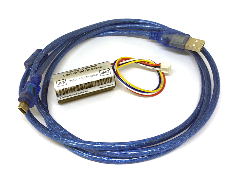
2. A modbus configuration cable
3. Tools to open the plastic housing of Lorawan sensors (L hex key or screwdriver)
Click to the link below to download Daviteq modbus configuration software:
https://filerun.daviteq.com/wl/?id=yDOjE5d6kqFlGNVVlMdFg19Aad6aw0Hs
After downloading the software, unzip the file named: Daviteq Modbus Configuration Tool.zip and then copy the
extracted folder to the storage drive for long-term use.
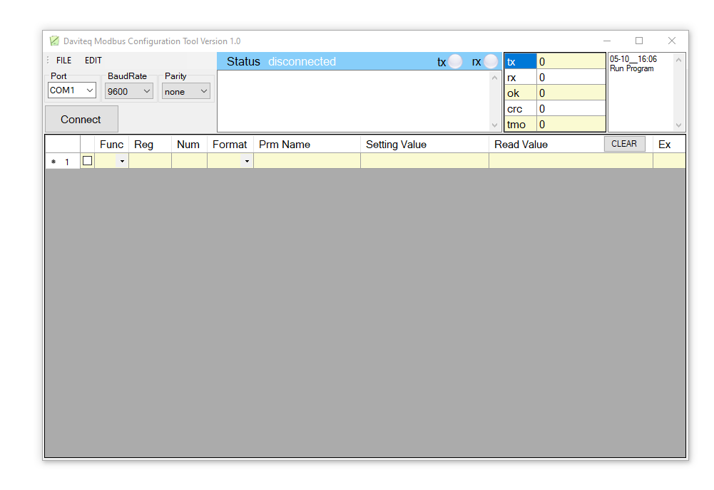
Open the folder, double click to the file Daviteq Modbus Configuration Tool Version.exe to launch the
software and the software interface as below:
Step 1: Connect the PC to the LoraWAN sensor using the configuration cable.
Offline configuration for LoRaWAN
sensors
1. Prepare equipment and tools
2. Download and launch Daviteq modbus
configuration software
Note: The software only runs on Microsoft Windows OS (win7 and above).
3. Connect the cable and configure the sensor

- Use the configuration cable (Item code: TTL-LRW-USB-
01).
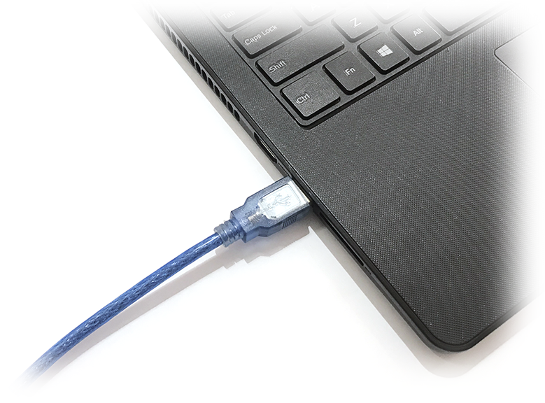
- Connect the USB-A plug into the USB-A socket of the
PC
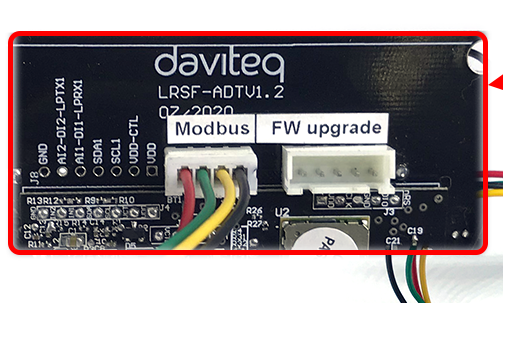
- Open the housing of the sensor.
- Plug the cable connector into sensor's modbus
configuration port.
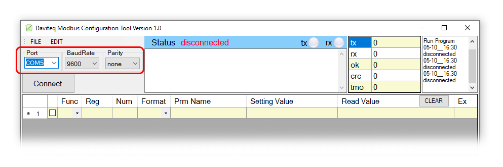
Step 2: On the configuration software, choose relevant Port (the USB port which is the cable plugged in) and set the
BaudRate: 9600, Parity: none
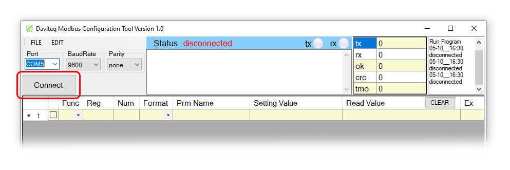
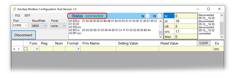
Step 3: Click “ Connect “ button to connect the software to the sensor. After successful connection, the connected
status(green text) will show on the software.

Step 4: Import the configuration file for the sensor to the software: click menu File/ Import New and then browse the
relevant sensor template file (csv file) and click Open to import the template file.
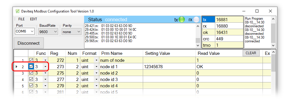
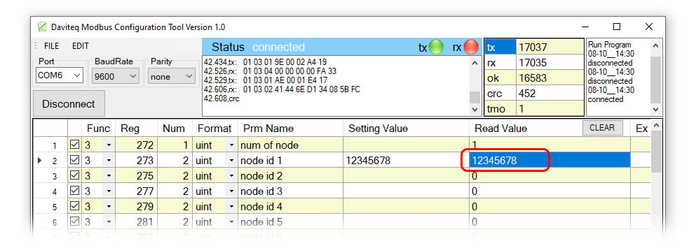
Step 5: Read current value of parameter with function 3
At the relavant row of the parameter, check the box 3 on the column Func to read the value of the parameter.
The read value is shown on Read value column.
Each sensor type has own template file. Refer to sensor's manual to download the correct file.
The sensor is only active for configuration in 60 seconds since plugging the configuration cable or the power
supply into the sensor.

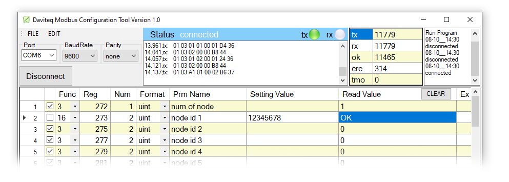
Step 6: Write the new setting to parameter with function 16
Double click on column Setting Value of the parameter and input new setting of the parameter
Uncheck the tick on Func column of the parameter, click on the arrow, select 16 and then check on the Func
column to write new setting to the parameter. The OK text will show on Read Column if the software successfully
writes the setting.
Repeat the step 5 to read the setting of the parameter for checking.
No.
Phenomena
Reason
Solutions
1
Status on the software always
shows Disconnected although
the configuration cable is
connected to the PC
The selected COM port is
incorrect.
The cable is defective
Select the correct COM port to
which the configuration cable
connects to PC
Check the cable
For some critical parameters of the sensor, the password in "password for setting" must be written before
writing the new settings to these parameters.
Only read/write registers are allowed to write
4. Troubleshooting

2
The software reads no value
after importing right template
and connecting right cable
The cable is defective or
loose connection
The USB port is defective
There is no power supply
to sensor via configuration
cable
The sensor is defective
Check or replace new
configuration cable
Check USB port
Check power line of the cable
Check the sensor
3
No COM port appears in the Port
list
No configuration cable is
plugged to PC
Cable driver is not
installed on PC
Plug the cable to PC
Install the driver for PC
4
The parameter table on the
software is empty
The template file has not
been imported
Go to File/Import New to import the
template file
5
The parameter table on the
software does NOT match the
memmap table of the sensor
The wrong template file is
imported
Go to the correct manual page of
the product and download right
template file, then import the
template file into the software
Manufacturer
Daviteq Technologies Inc
No.11 Street 2G, Nam Hung Vuong Res., An Lac Ward, Binh Tan Dist., Ho Chi
Minh City, Vietnam.
Tel: +84-28-6268.2523/4 (ext.122)
Email: info@daviteq.com | www.daviteq.com
Distributor in Australia and New
Zealand
Templogger Pty Ltd
Tel: 1800 LOGGER
Email: contact@templogger.net
5. Support contacts
Table of contents
Other daviteq Accessories manuals

daviteq
daviteq WS433-O2 User manual

daviteq
daviteq A420-FCL User manual

daviteq
daviteq WSSFC-ULA-01 User manual

daviteq
daviteq CAP10 User manual

daviteq
daviteq WS433-AC User manual

daviteq
daviteq WS433-DI User manual

daviteq
daviteq WS433-M12F-ATE User manual

daviteq
daviteq WS433-TAG User manual

daviteq
daviteq CAP10G User manual

daviteq
daviteq WSSFCB-NH3 User manual


