daviteq A420-FCL User manual


A420-FCL-01
JUN-2021
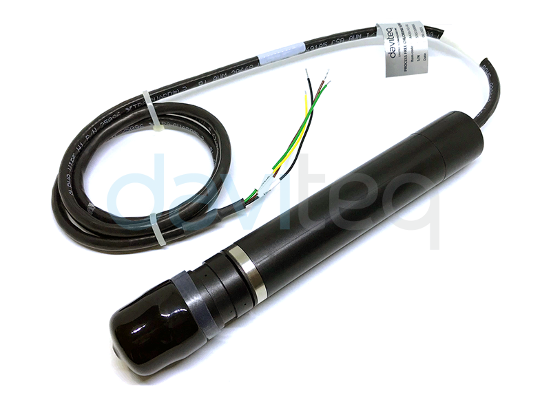
Free Chlorine Sensor with Analog output A420-FCL
The Chlorine Electrode is an amperometric (or polarographic) electrode (or “probe”) used for continuous measurement
of chlorine in drinking water, swimming pools, spas, industrial applications, or dirty/colored samples where colorimetric
methods are inadequate. A 3-electrode system is employed for ensuring good linearity between the output and the
chlorine concentration (up to 50 ppm). The bound membrane sensor cap provides good stability and durability for this
product. In addition, our proprietary Internal Filled Gel (IFG) significantly reduces the electrode measurement’s pH
dependence.
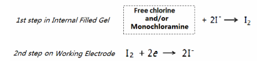
In principle, the chlorine electrode measures the total chlorine of the water sample via the measurement mechanism
described below. However, free chlorine measurement is also feasible when the chloramine concentration is negligible
or constant and calibrated for free chlorine.
User Guide For Free Chlorine
Sensor with Analog output A420-
FCL
This document is applied for the following products
1. Introduction

Sensing Technology
Two-electrode amperometric technology with gas permeable membranes
(replaceable)
Measuring range
0-10mg/L or 0-20mg/L
Accuracy & Resolution
+/- 0.1 mg/L
Repeatability
+/- 0.05 mg/L (25 oC)
Response Time
T90 < 90s (25 oC)
Working Condition
0 .. 50 oC with pH = 5 .. 9
Working Pressure
0 .. 15 psig
Flow range
30 .. 60 L/h or 0.6 .. 1.3 cm/s
Output
4-20mA
Power supply
6..12VDC, avg. < 200mA
Conditioning
New, first start-up: at least 4hours Restart-up: < 30 min.
Calibration
One Point - Manual with DPD
Interferences
ClO2, Ozone, Bromine Cyanuric Acid compatible
Process connection
1/2" NPT
Wetted parts
PVC, Silicone, ABS, PES
Silver-Silver Halide/Platinum
Sensor Cable
6m with BNC connector
Rating
IP68
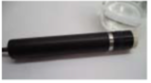
Sensor Dimension
D21.3 x 219 (mm)
Sensor net weight
< 200 grams
Warranty
1 year for probe, membrane for 03 months
The Chlorine Electrode is designed to operate with 9-24 VDC power. Connecting the electrode to any power outside the
normal range may result in electrode damage and void the warranty.
In addition to complying with the instructions included in this manual, be sure to follow the applicable
analyzer/controller/meter instructions regarding electrode wiring.
The membrane cap needs to be filled with Internal Filled Gel(IFG) before using the electrode.
Safety Data Sheets (SDS) for information on safe handling of chemicals for operating the electrode should be made
available to all personnel involved in installation, testing, and ongoing use, as needed.
2. Specification
3. Installation
IMPORTANT NOTES:

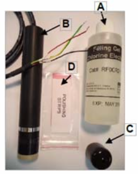
1. Ensure you have the necessary components to assemble the
electrode
Internal Filled Gel (IFG)
Electrode & Membrane Cap
Protection Boot
Electrode polishing strips
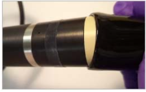
2. Remove the protection boot from the electrode or membrane cap
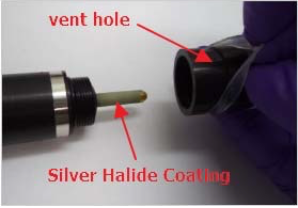
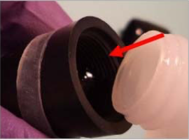
3. Lift the silicone band covering the vent hole. Make sure the vent hole
(see arrow in image) is open to air. Avoid using any sharp tools for this
step. Set the membrane cap aside.
► Note:Avoid damaging the Silver Halide Coating(gray portion)
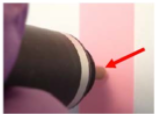
4. Polish the working electrode (WE) surface (see arrow) with the
polishing strip until it is shiny in appearance.
Polish the gold tip in one direction.
Do not over-polish – this should just take a few strokes on the
polishing strip
Avoid touching the silver halide coating
Rinse the electrode with DI water after polishing
5. Fill the membrane cap with Internal Filled Gel (IFG) to the upper
threads (red arrow).
► Note:DoNOTshaketheInternalFilledGel(IFG) before filling – this may
introduce problematic air bubbles.
3.1. Electrode Assembly steps 1-8

6. Make sure the silicone band is not covering the vent hole and screw
the membrane cap on the electrode until it is finger tight. The vent hole
will allow excess IFG to escape.
► Note:Do this step over a sink with running water to rinse away excess
IFG.
7. Push the silicone vent hole band back into the recess and rinse the
electrode thoroughly before using.
8. Wipe water off the electrode gently. Avoid touching the membrane
after assembly.
The electrode is now ready for polarization and conditioning steps.
Yellow: Vin+
Black: Vin-
Red: 4-20mA Input
Green: Ground, 0VDC
1. The standard cable length is 3 feet. If another cable length is needed, contact your supplier or manufacturer.
The maximum length should be no more than 30 feet to avoid signal loss.
2. The output current of power source should be more than 100 mA.
3. The A420-FCL output can be measured by multimeter or other devices which allow the analogue input and
measurement. The maximum loop resistance of the devices should be less than 400Ω for testing the current
output of A420-FCL (4-20mA version).
3.2. Electrode wiring
NOTE:

To achieve accurate measurements, an appropriate flow rate in the range of 30 to 60 L/hr is required to reach
equilibrium between the electrochemical consumption and the diffusion of chlorine. A beaker with magnetic stirrer can
be used for electrode evaluation or polarization in a lab environment, but for real continuous measurement
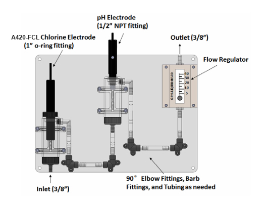
applications, a flow cell system is required. A diagram of a flow cell system for the A420-FCL electrode, a pH electrode,
and a flow regulator is shown in picture below.
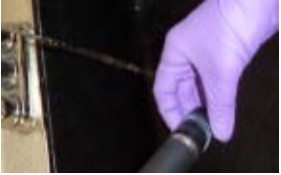
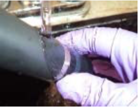
Make sure the stainless-steel ring on the A420-FCL chlorine electrode is completely submersed in the water
(above the stainless-steel counter electrode).
The flow regulator and 90o elbow tubing is important for the devices to maintain a constant flow rate. An
unstable flow rate will lead to an inaccurate chlorine measurement.
The flow regulator can be installed at INLET side as well.
Avoid bubbles adhering to the center hole of membrane cap. Bubbles in other areas of membrane cap are
acceptable.
Make sure to maintain a clear space of ~25mm (about 1”) between the tip of the sensor cap and the bottom of
the flow cell tube.
The output of A420-FCL is linear with chlorine concentration. As a result, a 2-point calibration determine the final
calculation equation. Usually, the zero and the half-scale points are recommended for calibrating A420-FCL.
For the zero point (1st point), it can be obtained in zero chlorine water during the conditioning processing. Generally,
the zero point of A420-FCL should be within the specification ranges provided in Tables 1 and 2. The zero point drift is
very slow and negligible in most cases. If the zero point of A420-FCL is not within the specification ranges, please
change the internal filled gel, clean the working electrode and polarize the probe in the zero-chlorine water again.
Please check the zero point every quarter or half a year at least for more precision.
For the half-scale point (2nd point), it is usually around the middle point of the measurement range and it is the most
important point for the accuracy of A420-FCL. In most cases, the calibration of A420-FCL is actually a 1-point
calibration while zero point drift can be ignored. Thus, the colorimetric DPD method (colorimeter, photometer or
spectrophotometer) is strongly recommended to standardize the exact concentration of chlorine at this point. There
are primarily two types of DPD Reagents commercially available:
1. DPD Free Chlorine Reagent (DPD Method #1) for measuring free chlorine.
3.3. Installation into a flow cell or similar system
NOTE:
4. Calibration

2. DPD Total Chlorine Reagent (DPD Method #4) for measuring total chlorine.
The operator should review and familiarize themselves with the DPD method, reagents, and devices to make sure
knowing how to perform this important calibration measurement.
PreparetheequipmentandDPDreagentsforafastandefficientmeasurement.
MakesuretheA420-FCLchlorineelectrodeisfullypolarizedandconditionedinzero-chlorinewaterand record the output
of zero point (the 1st point).
Make sure the electrode is installed properly inthe measurement system with a constant flowrate ranging from
30 L/hr to 60 L/hr (0.6 cm/s to 1.3 cm/s).
Add chlorine to the system, and preliminarily measure the chlorine concentration by DPDmethod.
Approximately adjust the chlorine concentration to the middle point of the measurement range by adding water
or chlorine if necessary.
Let the probe output be stable, and then take water samples from the measurement system for DPD
standardization. This sample should be close to the A420-FCL electrode location for best accuracy.
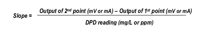
Record the output of A420-FCL (the 2nd point) as well as the chlorine reading from DPD test.
Calculate the slope as follows:
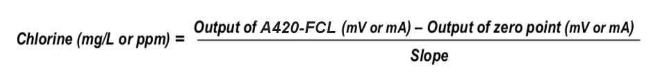
Once the slope is obtained, the electrode output including voltage (0-5V) or current (4-20 mA) can be converted into
“mg/L” or “ppm” in customers’ analyzer/controller/meter. The conversion equation for any of A420-FCL output is
below:
When the zero point of A420-FCL is not within specifications or there is no significant change in the measurement
environment, but the electrode reading is continuously increasing or decreasing (not fluctuating) within an hour, re-
polarization is probably needed. The root cause is that some interfering substances probably were brought to the
working electrode again, such as unsuccessfully polishing the surface of working electrode, changing the IFG, replacing
the membrane or soaking the electrode with the power off (unconnected) in chlorine or other strong oxidant solution
for a long time. The re- polarization process is mandatory until the electrode presents a stable output. If the zero point
of A420-FCL still can not meet the specifications after a reasonable amount of polarization time, changing the IFG or
polishing the working electrode again may be necessary, or adding tiny sodium thiosulfate in testing water for
removing the potential oxidizers.
If the zero point of the A420-FCL does not meet the listed specifications it may be necessary to change the IFG. The IFG
also needs be changed if the stainless-steel ring (counter electrode) is not submersed in the water when the electrode
is powered for more than 5 minutes. Also, when the slope is lower than 50% of the nominal value, changing the IFG
may correct this situation. It is important to disconnect/power off the electrode before removing it from the water.
Instructions for changing the IFG are as follows:
Calibration Preparation and Procedure
5. Maintenance
5.1. Electrode re-polarization
5.2. Changing the Internal Filled Gel (IFG)

1. Lift the vent hole band up and move it to the lower part of the membrane cap.
2. Unscrew the membrane cap from the electrode body.
3. Dump any residual IFG remaining in the cap or on the electrode body.
4. Rinse the membrane cap with DI water, then with 1-2 mL of new IFG.
5. Complete the IFG change as described in the section Electrode Assembly, from step 5 to step 8.
It is recommended to clean the membrane, when the center pore of the membrane cap is discolored (usually yellow or
brown) or if the slope is lower than 50 % of the nominal value after changing the IFG. This is not actually “cleaning”
the membrane, but rather the removal of extra iodine precipitates by Na2S, Na2S2O3 solution or Ethanol. The
recommended process is as follows:
1. Disconnect the electrode and unscrew the membrane capdiscard the IFG, and rinse the membrane cap and
the electrode with clean water.
2. Cover the working electrode (WE) and reference electrode (RE) parts with a paper towel and avoid exposure
to sunlight.
3. Prepare ~ 0.1 M Na2S2O3 or 95% Ethanol and pour ~150 ml in an appropriately sized beaker to allow the
membrane to be submerged.
4. Submerge the membrane cap in the solution completely for overnight. Use parafilm to cover the open of the
beaker during soaking.
5. Clear the cap by DI water and paper, refill IFG and screw onto electrode.
If the membrane cap gets damaged, the electrode reading is fluctuating, or the slope is lower than 30% of the nominal
value after changing the IFG and cleaning the membrane, the membrane cap may need to be replaced. Please make
sure the electrode is not powered during assembly and then follow the instruction below for replacement.
1. Unpack the membrane cap replacement kit and prepare the new membrane cap on a clean surface.
2. Unscrew the old membrane cap and discard it.
3. Rinse the new membrane cap with clean water, then rinse it with 1-2 mL of the IFG.
4. Follow the instructions from step 5 to step 8 as described in the Electrode Assembly section.
If the A420-FCL electrode reading is abnormal or the zero point is not within specifications after a reasonable
polarization time, the working electrode (WE) may not be able to completely polarize. Try to polish the WE again with
the polishing strip. In addition, if a stain or discoloration is visible on the surface of the WE, it should be polished until
the stain is less visible or removed completely. Please refer to Step 4 of Electrode Assembly section to brush the gold
reference electrode (RE) a few times in one direction, and then follow the next steps for electrode assembly.
The A420-FCL electrode can be stored in clean water or stored dry, preferably at normal room temperatures, while not
in use. It is recommended to:
1. Soak the electrode in clean water (IFG in cap) if it will be used within 1 week.
2. Store the electrode dry (IFG in cap) if it will be used within 1 month.
3. Store the electrode dry (without IFG in cap) for longer than 1-month storage.
5.3. Cleaning the Membrane Cap (De-iodine)
5.4. Replacing the Membrane Cap
5.5. Polishing the Working Electrode (WE)
5.6. Storing the Electrode
NOTE: The reference electrode is light sensitive and should be capped or covered during storage
6. Troubleshooting

Problem
Possible Cause
Solution
No reading (1)
Insufficient conditioning.
Reading should appear within 10
mins.
No reading (2)
Electrode connection or power
supply.
Check connection/wiring.
No reading and electrode feels warm
PCB shorted or corrupted.
Replace electrode
Zero point out of specification
1. Water sample is not
chlorine free
2. Insufficient
polarization/conditioning
3. Interfering substances
cannot be cleaned
electrochemically.
1. Replace the zero chlorine
water.
2. Continue polarizing
andconditioning electrode.
3. Brush WE with polishing
strip.
Reading instable or fluctuation
1. Membrane cap fouled or
damaged.
2. Air bubbles on outside of
membranecap – especially
at center pore
3. Air bubbles inside the
membrane cap.
1. Clean or change membrane
cap.
2. Shake the electrode to
remove theair bubbles from
the center pore.
3. Shake electrode or inspect
the cap for air bubbles
Slope too low
1. Membrane cap fouled.
2. IFG deterioration.
3. Insufficient conditioning
4. Flow rate too low.
5. Erroneous DPD
standardization.
1. Clean or change membrane
cap.
2. Refill IFG.
3. Recondition the electrode.
4. Adjust flow rate into
working range.
5. Check the measurement
range of the DPD and
recalibrate.
Reading out of range
1. Chlorine content >
maximum measuring range.
2. Electrode and membrane
cap are unmatched or
improperly attached.
1. Confirm actual sample or
electrode range
specification
2. Reinstall the membrane cap
looser or slightly tighter.
Replace the membrane cap.
7. Package Include:

Manufacturer
Daviteq Technologies Inc
No.11 Street 2G, Nam Hung Vuong Res., An Lac Ward,
Binh Tan Dist., Ho Chi Minh City, Vietnam.
Tel: +84-28-6268.2523/4 (ext.122)
Email: info@daviteq.com | www.daviteq.com
Distributor in Australia and New Zealand
Templogger Pty Ltd
Tel: 1800 LOGGER
Email: contact@templogger.net
8. Support contacts:
Table of contents
Other daviteq Accessories manuals

daviteq
daviteq WS433-M12F-ATE User manual

daviteq
daviteq WS433-DI User manual

daviteq
daviteq WSSFC-V1A-025 User manual

daviteq
daviteq WSSFC-ULA-01 User manual

daviteq
daviteq WS433-O2 User manual

daviteq
daviteq WS433-TAG User manual

daviteq
daviteq CAP10 User manual

daviteq
daviteq WSSFC-AC User manual

daviteq
daviteq CAP10G User manual

daviteq
daviteq WS433-AC User manual


.png)
.png)