manuals.online logo
Brands
  1. Home
  2. •
  3. Brands
  4. •
  5. DeLOCK
  6. •
  7. Switch
  8. •
  9. DeLOCK 88015 User manual

DeLOCK 88015 User manual

Declaration of conformity
Products with a CE symbol fulll the EMC directive (2014/30/EU) and
RoHS directive (2011/65/EU+2015/863+2017/2102), which were released by the
EU-comission.
The declaration of conformity can be downloaded here:
https://www.delock.de/produkte/G_88015/merkmale.html
WEEE-notice
The WEEE (Waste Electrical and Electronic Equipment)-directive, which became
e󰀨ective as European law on February 13th 2003, resulted in an all out change
in the disposal of disused electro devices. The primarily purpose of this directive
is the avoidance of electrical waste (WEEE) and at the same time the support of
recycling and other forms of recycling in order to reduce waste. The WEEE-logo
on the device and the package indicates that the device should not be disposed
in the normal household garbage. You are responsible for taking the disused
electrical and electronical devices to a respective collecting point. A separated
collection and reasonable recycling of your electrical waste helps handling the
natural resources more economical. Furthermore recycling of electrical waste is
a contribution to keep the environment and thus also the health of men. Further
information about disposal of electrical and electronical waste, recycling and
the collection points are available in local organizations, waste management
enterprises, in specialized trade and the producer of the device.
Cet appareil
se recycle
Points de collecte sur www.quefairedemesdechets.fr
EU Import: Tragant Handels- und Beteiligungs GmbH
Beeskowdamm 13/15, 14167 Berlin, Germany
Support Delock
If you have further questions, please contact our customer support
[email protected]
You can nd current product information on our homepage: www.delock.com
Final clause
Information and data contained in this manual are subject to change without notice
in advance. Errors and misprints excepted.
Copyright
No part of this user's manual may be reproduced, or transmitted for any purpose,
regardless in which way or by which means, electronically or mechanically, without
explicit written approval of Delock.
Edition: 08/2023
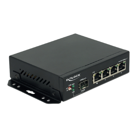
Industrial Gigabit Ethernet Switch
4 Port RJ45 2 Port SFP
User manual
Mode d’emploi
Uživatelská příručka
Manuale utente
Manual de utilizare
Korisnički priručnik
Bedienungsanleitung
Manual del usuario
Instrukcja obsługi
Bruksanvisning
Használati utasítás
Εγχειρίδιο χρήστη
Product-No: 88015
User manual no: 88015-a
www.delock.com
English
Description
This robust, industry capable Gigabit Ethernet switch by Delock can be used to
connect di󰀨erent network components.
Two SFP uplink ports with 1 Gbps o󰀨er exible connection options.
Redundant power supply with 9 V to 48 V
The switch accepts two terminal power sources, allowing it to be permanently
connected to multiple power sources, enabling applications that require high
availability.
Specication
• Connectors:
4 x RJ45 jack for 10/100/1000 Mbps Base-T
2 x SFP slot for 1 Gbps SFP module
1 x 5 pin terminal power connector
• Data transfer rate up to 1 Gbps
• Supports IEEE 802.3 / 802.3u / 802.3z / 802.3ab
• VLAN port Isolation
• LEDs for status monitoring
• Redundant power supply with 9 V to 48 V
• Power consumption: max. 6 W
• Robust metal housing
• Fanless
• Suitable for 35 mm DIN rail
• Protection class: IP40
• Operating temperature: -40 °C ~ 85 °C
• Dimensions (LxWxH): ca. 116 x 85 x 33 mm
System requirements
• Power supply with DC 9 V - 48 V (not included)
Package content
• Switch
• User manual
Safety instructions
• Protect the product against moisture
• Protect the product against direct sunlight
Installation
• TP interface
Connect the network devices with TP cable to the RJ45 ports of the switch.
• SFP interface
Slide the optional SFP module into the SFP slot and push until you hear a click.
Connect a ber cable from the SFP module to the ber network.
• Power
Connect a suitable power source to the terminal block and check that the Power
LED lights up.
• DIP Switch settings
DIP1 DIP2 Mode
OFF OFF Default
ON OFF VLAN Port Isolation
1. Default mode
DIP switch 1 and 2 are by factory default both in OFF position; the uplink and
downlink ports are interconnected.
2. One Key VLAN (Port Isolation)
Data forwarding is not available between the copper ports of the switch, they can
only communicate with the uplink port, ensuring e󰀨ective data transfer and a safe
system.
Conguration système requise
• Source d'alimentation avec CC 9 V - 48 V (non fourni)
Contenu de l’emballage
• Commutateur
• Mode d’emploi
Instructions de sécurité
• Protéger le produit contre l’humidité
• Protéger le produit contre la lumière directe du soleil
Installation
• Interface TP
Connectez les périphériques réseau avec le câble TP aux ports RJ45 du
commutateur.
• Interface SFP
Faites coulisser le module SFP optionnel dans l'emplacement SFP et poussez
jusqu'à ce que vous entendiez un déclic. Connectez un câble bre depuis le
module SFP jusqu’au réseau bre.
• Alimentation
Connecter une source d’alimentation appropriée au bornier et vérier que la LED
d’alimentation s’allume.
• Réglages du commutateur DIP
DIP1 DIP2 Mode
ARRÊT ARRÊT Par défaut
MARCHE ARRÊT Isolation port VLAN
1. Mode par défaut
Les commutateurs DIP 1 et 2 sont réglés tous les deux par défaut en usine
sur la position ARRÊT ; les ports liaison montante et liaison descendante sont
interconnectés.
2. VLAN une touche (Isolation de port)
Le transfert de données n'est pas disponible entre les ports cuivre du
commutateur, ils peuvent uniquement communiquer avec le port liaison montante,
garantissant un transfert de données e󰀩cace et un système sûr.
English
Deutsch
Français
Español
Systemvoraussetzungen
• Netzteil mit DC 9 V - 48 V (nicht im Lieferumfang)
Packungsinhalt
• Umschalter
• Bedienungsanleitung
Sicherheitshinweise
• Produkt vor Feuchtigkeit schützen
• Produkt vor direkter Sonneneinstrahlung schützen
Installation
• TP Schnittstelle
Schließen Sie die Netzwerkgeräte mit TP Kabel an die RJ45 Buchsen des
Switches an.
• SFP Schnittstelle
Schieben Sie das optionale SFP Modul in den SFP Schacht, bis es hörbar
einrastet. Schließen Sie ein LWL Kabel zwischen dem SFP Modul und dem
Netzwerk an.
• Power
Schließen Sie eine geeignete Stromquelle an den Terminalblock an und
überprüfen Sie, ob die Power-LED leuchtet.
• DIP-Schalter-Einstellungen
DIP1 DIP2 Modus
OFF OFF Standard
ON OFF VLAN Port Isolation
1. Standardmodus
DIP-Schalter 1 und 2 sind werkseitig in der Position OFF; die Uplink- und
Downlink-Ports sind untereinander verbunden.
2. Ein-Tasten VLAN (Port-Isolation)
Eine Datenübertragung zwischen den Kupfer-Ports des Switches ist nicht möglich;
sie können nur mit dem Uplink-Port kommunizieren, wodurch eine e󰀨ektive
Datenübertragung und ein sicheres System erreicht wird.
Requisitos del sistema
• Fuente de alimentación con 9 V - 48 V CC (no incluida)
Contenido del paquete
• Conmutador
• Manual del usuario
Instrucciones de seguridad
• Proteja el producto contra el polvo
• Proteja el producto contra la luz solar directa
Instalación
• Interfaz TP
Conecte los dispositivos de red con el cable TP a los puertos RJ45 del
conmutador.
• Interfaz SFP
Deslice el módulo SFP opcional en la ranura SFP y empuje hasta que escuche
un clic. Conecte un cable de bra desde el módulo SFP a la red de bra.
• Alimentación
Conecte una fuente de alimentación adecuada al bloque de terminales y
compruebe que el LED de alimentación se ilumina.
• Conguración del conmutador DIP
Modo DIP1 DIP2
DESACTIVADO DESACTIVADO Predeterminado
ACTIVADO DESACTIVADO Aislamiento del puerto VLAN
1. Modo predeterminado
Los conmutadores DIP 1 y 2 se encuentran establecidos en la posición
DESACTIVADO de fábrica; los puertos ascendente y descendente están
interconectados.
2. VLAN de una clave (aislamiento de puerto)
El reenvío de datos no está disponible entre puertos de cobre del conmutador.
Solamente se pueden comunicar con el puerto ascendente, lo que garantiza la
transferencia ecaz de datos y un sistema seguro.
České
Polsku
Italiano
Svenska
Systémové požadavky
• Napájecí zdroj s DC 9 V - 48 V (není součástí balení)
Obsah balení
• Switch (přepínač)
• Uživatelská příručka
Bezpečnostní pokyny
• Chraňte produkt před vlhkostí
• Chraňte produkt před přímým slunečním světlem
Instalace
• TP rozhraní
Připjte síťová zařízení TP kabelem k portům RJ45 switche.
• SFP rozhraní
Vložte volitelný SFP modul do SFP slotu a tlačte dokud neuslyšíte kliknutí.
Připojte optický kabel od SFP modul k optické síti.
• Napájení
Připojte ke svorkovnici vhodný zdroj proudu a zkontrolujte, zda se rozsvítí LED
napájení.
• Nastavení DIP přepínače
DIP1 DIP2 Mód
OFF OFF tovární nastavení
ON OFF VLAN Izolace portu
1. Mód továrního nastavení
DIP přepínače 1 a 2 jsou oba v továrním nastavení v pozici OFF; porty uplink a
downlink jsou vzájemně propojeny.
2. One Key VLAN (Izolace portu)
Přeposílání dat není možné mezi porty ethernetového spoje switche, pro zajištění
efektivního přenosu dat a bezpečného systému mohou komunikovat pouze s
portem uplink.
Requisiti di sistema
• Alimentazione con DC 9 V - 48 V (non inclusa)
Contenuto della confezione
• Switch
• Manuale utente
Istruzioni per la sicurezza
• Proteggere il prodotto dall'umidità
• Proteggere il prodotto dalla luce solare diretta
Installazione
• Interfaccia TP
Collegare i dispositivi di rete con il cavo TP alle porte RJ45 dello switch.
• Interfaccia SFP
Far scorrere il modulo SFP opzionale nello slot SFP e spingere nché non si
avverte un clic. Collegare il cavo in bra dal modulo SFP alla rete in bra.
• Alimentazione
Collegare una fonte di alimentazione adeguata alla morsettiera e vericare che il
LED di alimentazione si accenda.
• Impostazioni DIP switch
DIP1 DIP2 Modalità
OFF OFF Predenito
ON OFF Isolamento porta VLAN
1. Modalità predenita
I DIP switch 1 e 2 per impostazione predenita sono in posizione OFF; le porte
uplink e downlink sono interconnesse.
2. VLAN con un tasto (isolamento porta)
L'inoltro di dati non è disponibile tra le porte in rame dello switch. Possono
comunicare solo con la porta uplink, garantendo un e󰀩cace trasferimento dei dati
e un sistema protetto.
Wymagania systemowe
• Zasilacz DC 9 V - 48 V (nie znajduje się na wyposażeniu)
Zawartość opakowania
• Przełącznik
• Instrukcja obsługi
Instrukcje bezpieczeństwa
• Produkt należy zabezpieczyć przed wilgocią
• Produkt należy zabezpieczyć przed bezpośrednim światłem słonecznym
Instalacja
• Złącze TP
Podłącz urządzenia sieciowe za pomocą kabla TP do portów RJ45 przełącznika.
• Złącze SFP
Wsuń opcjonalny moduł SFP do gniazda SFP i popchnij go, aż do usłyszenia
kliknięcia. Podłącz światłowód z modułu SFP do sieci światłowodowej.
• Moc
Podłącz odpowiednie źródło zasilania do listwy zaciskowej i sprawdź, czy świeci
się dioda LED zasilania.
• Ustawienia przełącznika DIP
Tryb DIP1 DIP2
OFF OFF Default (WYŁ. WYŁ. Domyślne)
ON OFF VLAN Port Isolation (WŁ. WYŁ. Izolacja portu VLAN)
1. Tryb domyślny
Przełączniki DIP 1 i 2 są oba domyślnie ustawione fabrycznie na położenie OFF
(WYŁ.); Porty uplink and downlink są ze sobą połączone.
2. Jednoklawiszowy VLAN (Izolacja portu)
Przekierowywanie danych jest niedostępne pomiędzy portami miedzianymi w
przełącznika. Mogą one jedynie komunikować się z portem uplink zapewniając
skuteczną transmisję danych i bezpieczeństwo systemu.
Systemkrav
• Strömförsörjning med DC 9 V - 48 V (medföljer ej)
Paketets innehåll
• Switch
• Bruksanvisning
Säkerhetsinstruktioner
• Skydda produkten mot fukt
• Skydda produkten mot direkt solljus
Installation
• TP-gränssnitt
Anslut nätverksenheterna med TP-kabel till RJ45-portarna på switchen.
• SFP-gränssnitt
Skjut in SFP-modulen (tillval) i SFP-platsen och tryck in den tills det hörs ett klick.
Anslut en berkabel från SFP-modulen till bernätverket.
• Ström
Anslut lämplig strömkälla till anslutningsplinten och kontrollera att strömlysdioden
tänds.
• Inställningar för DIP-switch
DIP1 DIP2-läge
AV AV Standard
PÅ AV VLAN Isolering av port
1. Standardläge
Både DIP-switch 1 och 2 är fabriksinställda i läget AV; de över- och underordnade
länkportarna är sammankopplade.
2. VLAN med en nyckel (Isolering av port)
Vidarebefordran av data är inte tillgängligt mellan switchens kopparportar, de kan
endast kommunicera med den överordnade länkporten, vilket garanterar e󰀨ektiv
dataöverföring och ett säkert system.
Preduvjeti sustava
• Izvor napajanja s DC 9 V - 48 V (nije uključena)
Sadržaj pakiranja
• Preklopnik
• Korisnički priručnik
Sigurnosne upute
• Zaštitite proizvod od vlage
• Zaštitite proizvod od izravne sunčeve svjetlosti
Instalacija
• TP sučelje
Povežite mrežne uređaje pomoću TP kabela na RJ45 priključke preklopnika.
• SFP sučelje
Umetnite dodatni SFP modul u SFP utor i pritisnite ga tako sjedne na svoje
mjesto. Povežite optički kabel sa SFP modula na optičku mrežu.
• Napajanje
Spojite odgovarajući izvor napajanja na terminalni blok i provjerite svijetli li LED
za napajanje.
• Postavke DIP sklopke
DIP1 DIP2 način rada
ISKLJUČENO ISKLJUČENO Zadano
UKLJUČENO ISKLJUČENO Izolacija priključka
1. Zadani način rada
DIP sklopke 1 i 2 su prema tvorničkoj postavci u ISKLJUČENOM položaju; odlazni
i dolazni priključci su međusobno povezani.
2. One Key VLAN (Izolacija priključka)
Prosljeđivanje podataka nije moguće između bakrenih priključaka preklopnika.
Oni mogu komunicirati samo putem odlaznog priključka, što osigurava učinkovit
prijenos podataka i sigurnost sustava.
Română
Magyar
Hrvatski
ελληνικά
Cerinte de sistem
• Alimentare cu DC 9 V - 48 V (nu este inclusă)
Pachetul contine
• Switch
• Manual de utilizare
Instrucţiuni de siguranţă
• Protejaţi produsul împotriva umidităţii
• Protejaţi produsul împotriva luminii directe a soarelui
Instalarea
• Interfaţă TP
Conectaţi dispozitivele de reţea cu cablul TP la porturile RJ45 ale switch-ului.
• Interfaţă SFP
Glisaţi modulul SFP opţional în fanta SFP şi împingeţi până când auziţi un clic.
Conectaţi un cablu de bră optică de la modulul SFP la reţeaua de bră optică.
• Alimentare
Conectați o sursă de alimentare adecvată la blocul de borne și vericați dacă
LED-ul de alimentare se aprinde.
• Setări switch DIP
Mod DIP1 DIP2
Oprit Oprit implicit
Pornit Oprit pentru izolare port VLAN
1. Mod implicit
Switch-urile DIP 1 şi 2 sunt în poziţia Oprit ca setare implicită din fabrică; porturile
de link ascendent şi de link descendent sunt interconectate.
2. VLAN cu o cheie (izolare port)
Redirecţionarea datelor nu este disponibilă între porturile de cupru ale switch-
ului, acestea pot comunica doar cu portul de link ascendent, asigurând un transfer
ecient al datelor şi un sistem sigur.
Rendszerkövetelmények
• Tápegység DC 9 V - 48 V (nem tartozék)
A csomag tartalma
• Kapcsoló
• Használati utasítás
Biztonsági óvintézkedések
• Óvja a terméket a nedvességtől.
• Óvja a terméket a közvetlen napsugárzástól.
Telepítése
• TP-csatoló
Csatlakoztassa a hálózati eszközöket a TP-kábellel a kapcsoló RJ45 portjaihoz.
• SFP-csatoló
Csúsztassa az opcionális SFP-modult az SFP-aljzatba, és tolja be addig, amíg
egy kattanó hangot nem hall. Csatlakoztasson egy optikai szálakból álló kábelt
az SFP-modultól a száloptikai hálózathoz.
• Tápfeszültség
Csatlakoztasson egy megfelelő tápellátást az időszakos blokkba és ellenőrizze,
hogy a táp LED fények felgyulladtak-e.
• DIP-kapcsoló beállításai
DIP1 DIP2 mód
KI KI Alapértelmezett
BE KI VLAN Portizoláció
1. Alapértelmezett mód
Az 1. és 2. DIP-kapcsoló egyaránt KI helyzetbe van állítva gyárilag; az uplink és a
downlink portok össze vannak kapcsolva.
2. Egykulcsos VLAN (Portizoláció)
Az adattovábbítás nem lehetséges a kapcsoló rézportjai között. Ezek kizárólag
az uplink porttal kommunikálhatnak, hogy az adatátvitel hatékony és a rendszer
biztonságos legyen.
Απαιτήσεις συστήματος
• Τροφοδοσία ρεύματος με DC 9 V - 48 V (δε συμπεριλαμβάνεται)
Περιεχόμενα συσκευασίας
• Διακόπτης
• Εγχειρίδιο χρήστη
Οδηγίες ασφάλειας
• Προστατεύστε το προϊόν από την υγρασία
• Προστατεύστε το προϊόν από την άμεση ηλιακή ακτινοβολία
Εγκατάσταση
• Διασύνδεση TP
Συνδέστε τις συσκευές δικτύου με το καλώδιο TP στις θύρες RJ45 του διακόπτη.
• Διασύνδεση SFP
Σύρετε την προαιρετική μονάδα SFP μέσα στην υποδοχή SFP και πιέστε μέχρι
να ακούσετε ένα κλικ. Συνδέστε ένα καλώδιο οπτικών ινών από τη μονάδα SFP
στο δίκτυο οπτικών ινών.
• Ισχύς
Συνδέστε μια κατάλληλη παροχή ενέργειας στο κυτίο διανομής και ελέγξτε πως η
ένδειξη Ρεύματος LED ανάβει.
• Ρυθμίσεις διακόπτη DIP
DIP1 DIP2 Λειτουργία
ΑΠΕΝΕΡΓΟΠΟΙΗΣΗ ΑΠΕΝΕΡΓΟΠΟΙΗΣΗ Προεπιλογή
ΕΝΕΡΓΟΠΟΙΗΣΗ ΑΠΕΝΕΡΓΟΠΟΙΗΣΗ VLAN Απομόνωση θύρας
1. Προεπιλεγμένη λειτουργία
Οι διακόπτες DIP 1 και 2 έχουν τεθεί εργοστασιακά στη θέση ΑΠΕΝΕΡΓΟΠΟΙΗΣΗ.
Οι θύρες uplink και downlink είναι διασυνδεδεμένες.
2. One Key VLAN (Απομόνωση θύρας)
Η διαβίβαση δεδομένων δεν είναι διαθέσιμη μεταξύ των χάλκινων θυρών του
διακόπτη, μπορούν να επικοινωνούν μόνο με τη θύρα uplink, διασφαλίζοντας την
αποτελεσματική μεταφορά δεδομένων και ένα ασφαλές σύστημα.
Other DeLOCK Switch manuals

DeLOCK 87588 User manual

DeLOCK

DeLOCK 87588 User manual

DeLOCK 11500 User manual

DeLOCK

DeLOCK 11500 User manual

DeLOCK 11367 User manual

DeLOCK

DeLOCK 11367 User manual

DeLOCK 64226 User manual

DeLOCK

DeLOCK 64226 User manual

DeLOCK 87704 User manual

DeLOCK

DeLOCK 87704 User manual

DeLOCK 87699 User manual

DeLOCK

DeLOCK 87699 User manual

DeLOCK 87762 User manual

DeLOCK

DeLOCK 87762 User manual

DeLOCK 64236 User manual

DeLOCK

DeLOCK 64236 User manual

DeLOCK 62653 User manual

DeLOCK

DeLOCK 62653 User manual

DeLOCK 64155 User manual

DeLOCK

DeLOCK 64155 User manual

DeLOCK 87637 User manual

DeLOCK

DeLOCK 87637 User manual

DeLOCK 62900 User manual

DeLOCK

DeLOCK 62900 User manual

DeLOCK 63919 User manual

DeLOCK

DeLOCK 63919 User manual

DeLOCK 64234 User manual

DeLOCK

DeLOCK 64234 User manual

DeLOCK 63264 User manual

DeLOCK

DeLOCK 63264 User manual

DeLOCK 87729 User manual

DeLOCK

DeLOCK 87729 User manual

DeLOCK 87765 User manual

DeLOCK

DeLOCK 87765 User manual

DeLOCK 18600 User manual

DeLOCK

DeLOCK 18600 User manual

DeLOCK 62793 User manual

DeLOCK

DeLOCK 62793 User manual

DeLOCK 63739 User manual

DeLOCK

DeLOCK 63739 User manual

DeLOCK 63261 User manual

DeLOCK

DeLOCK 63261 User manual

DeLOCK 87758 User manual

DeLOCK

DeLOCK 87758 User manual

DeLOCK 18683 User manual

DeLOCK

DeLOCK 18683 User manual

DeLOCK 61100 User manual

DeLOCK

DeLOCK 61100 User manual

Popular Switch manuals by other brands

NETGEAR GSM7212 - ProSafe Switch Cli reference guide

NETGEAR

NETGEAR GSM7212 - ProSafe Switch Cli reference guide

Vemer memo BT1 GPS user manual

Vemer

Vemer memo BT1 GPS user manual

Comtrend Corporation GS-7608 Quick installation guide

Comtrend Corporation

Comtrend Corporation GS-7608 Quick installation guide

NETGEAR ProSAFE GS105PE installation guide

NETGEAR

NETGEAR ProSAFE GS105PE installation guide

HP A5120 EI Series Configuration guide

HP

HP A5120 EI Series Configuration guide

Aluprof AC250-02 ASSEMBLY AND PROGRAMMING MANUAL

Aluprof

Aluprof AC250-02 ASSEMBLY AND PROGRAMMING MANUAL

Linksys DSHUB24 Specifications

Linksys

Linksys DSHUB24 Specifications

MESA ENGINEERING CAB CLONE IR+ owner's manual

MESA ENGINEERING

MESA ENGINEERING CAB CLONE IR+ owner's manual

TP-Link TL-SF1005P installation guide

TP-Link

TP-Link TL-SF1005P installation guide

Dungs GGW A4 Series instructions

Dungs

Dungs GGW A4 Series instructions

Enterasys Matrix E5 5H153-50-G user guide

Enterasys

Enterasys Matrix E5 5H153-50-G user guide

Allied Telesis IE340 Series Command reference

Allied Telesis

Allied Telesis IE340 Series Command reference

Inateck SC01001 instruction manual

Inateck

Inateck SC01001 instruction manual

Honeywell DDS76-1/2 Installation instruction

Honeywell

Honeywell DDS76-1/2 Installation instruction

Aguilar aguilar OBP-3 Wiring diagram

Aguilar

Aguilar aguilar OBP-3 Wiring diagram

StarTech.com SV431DPUA instruction manual

StarTech.com

StarTech.com SV431DPUA instruction manual

Automatic Technology Smart Phone Control Kit installation instructions

Automatic Technology

Automatic Technology Smart Phone Control Kit installation instructions

TP-Link UH400 user guide

TP-Link

TP-Link UH400 user guide

manuals.online logo
manuals.online logoBrands
  • About & Mission
  • Contact us
  • Privacy Policy
  • Terms and Conditions

Copyright 2025 Manuals.Online. All Rights Reserved.