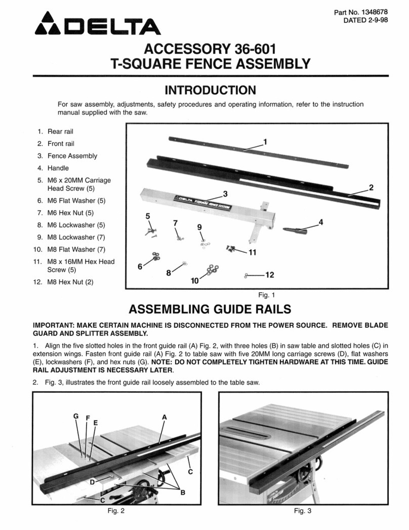
Delta InfraSuite RWD030R User manual

www.deltapowersolutions.com
The power behind competitiveness
Delta InfraSuite Precision Cooling
RowCool
Air Cooled Type (RWD030R)
User Manual

InfraSuite R Series – Air Cooled Type 2
SAVE THIS MANUAL
This manual contains important instructions and warnings that you should follow during
the installation, operation, storage and maintenance of this product. Failure to heed these
instructions and warnings will void the warranty.
Copyright © 2021 by Delta Electronics Inc. All Rights Reserved. All rights of this User Manual
(“Manual”), including but not limited to the contents, information, and figures are solely
owned and reserved by Delta Electronics Inc. (“Delta”). The Manual can only be applied to
the operation or the use of this product. Any disposition, duplication, dissemination,
reproduction, modification, translation, extraction, or usage of this Manual in whole or in part
is prohibited without the prior written permission of Delta. Given that Delta will continuously
improve and develop the product, changes may be made to the information in this Manual
at any time without obligation to notify any person of such revision or changes. Delta will
make all possible efforts to secure the accuracy and the integrity of this Manual. Delta
disclaims any kinds or forms of warranty, guarantee, or undertaking, either expressly or
implicitly, including but not limited to the completeness, faultlessness, accuracy, non-
infringement, merchantability or fitness for a particular purpose of the Manual.

3
Table of Contents
Chapter 1 : Safety Instructions ..............................................................................................5
1.1General ..................................................................................................................5
1.2Installation Warnings .............................................................................................5
1.3Operation Warnings...............................................................................................6
Chapter 2 : Introduction .........................................................................................................7
2.1Package List ..........................................................................................................7
2.2Appearance .........................................................................................................10
2.3Components Identification ...................................................................................12
Chapter 3 : Installation.........................................................................................................15
3.1Location and Power Considerations....................................................................15
3.1.1Clearance Zone .......................................................................................16
3.1.2Handling ...................................................................................................18
3.1.3Remove the Transport Fasteners from the Compressor .........................19
3.1.4Positioning................................................................................................20
3.1.5Outdoor Unit Installation ..........................................................................24
3.1.6Outdoor Side Cover Installation...............................................................25
3.2Installation of Pipeline..........................................................................................29
3.2.1Refrigerant Piping ....................................................................................29
3.2.1.1Installation of the Protection Cover for Piping..........................................30
3.2.2Condenser Drain Connection...................................................................30
3.2.3Opening Hole and Related Locations ......................................................33
3.3Connection of Cables ..........................................................................................34
3.3.1Connecting the Power Cable (Use Accessory Pack Item: 3 Cable
Gland) .....................................................................................................34
3.3.2Connecting the Signal Cables..................................................................41
3.3.3Connecting the External Temperature and Humidity Sensor...................47
3.4System Management...........................................................................................49
3.4.1Charging Refrigeration Oil .......................................................................49
3.4.2Pressure Leak Test ..................................................................................49
3.4.3Vacuum Pumping .....................................................................................50
Chapter 4 : Initial Startup.....................................................................................................51
InfraSuite R Series – Air Cooled Type 4
4.1Pre-start Inspection..............................................................................................51
4.2Power On.............................................................................................................52
4.3Charging Refrigerant ...........................................................................................53
Chapter 5 : Operation ..........................................................................................................55
5.1Main Page............................................................................................................55
5.2Account Authority and Login................................................................................56
5.3How to Operate the Main Page ...........................................................................58
5.4Startup .................................................................................................................60
5.4.1Operating Settings ...................................................................................60
5.4.2Startup......................................................................................................61
5.5Inquiry of System Status......................................................................................62
5.5.1System Status..........................................................................................62
5.5.2Data History .............................................................................................63
5.5.3Warning....................................................................................................64
5.5.4Historical Event ........................................................................................65
5.5.5Run Hours ................................................................................................66
5.5.6Group Setting...........................................................................................67
5.6Summary of Parameters Settings........................................................................68
5.7Shutdown.............................................................................................................75
Chapter 6 : Troubleshooting ................................................................................................76
Appendix 1 : Technical Specifications .................................................................................85
Appendix 2 : Warranty .........................................................................................................86
Appendix 3 : Maintenance ...................................................................................................87

5
Chapter 1 : Safety Instructions
1.1 General
Carefully read all chapters of the Manual before any installation, operation, or
maintenance. To avoid personal injuries and damaging the equipment, be sure to
operate the product in accordance with the instructions in this Manual and the markings
on the cabinet.
When moving the equipment, the unit should only be moved by at least two people so
as to guarantee safety.
In handling or removal of the equipment, pay attention to its height and center of gravity.
When using a transportation tool for handling, it must be raised from the bottom to
avoid toppling.
The unit contains moving components. Be careful to keep it away from your arms, legs,
hair, clothes or jewelry so as to avoid any danger.
This appliance is not intended for use by persons (including children) with reduced
physical, sensory or mental capabilities, or lack of experience and knowledge, unless
they have been given supervision or instruction concerning use of the appliance by a
person responsible for their safety.
Children should be supervised to ensure that they do not play with the appliance
1.2 Installation Warnings
The unit can be connected with a single or dual power source. Make sure the input
power is disconnected before making a connection. If necessary, use a multi-meter to
confirm this.
There shall not be any flammable objects in the installation area, and the equipment
must be installed on a stable floor.
This indoor unit is only intended for indoor use. The indoor environment must be
separated from the outside air so as to avoid temperature and humidity interference.
Consult the national or local regulations for separating the installation environment.
All specifications such as connection and length of cables must be in compliance with
local or national laws and regulations.
The refrigerant connection piping between the indoor unit and the outdoor unit should
be insulated to prevent personnel from being exposed to high temperatures.

InfraSuite R Series – Air Cooled Type 6
1.3 Operation Warnings
Please read these operating instructions before operation.
The high voltage and high-pressure in the equipment can cause personal injuries! The
components may have hidden dangers and only authorized service personnel can
operate the unit. Improper operation may lead to serious injury or death or equipment
damage. Be sure to follow all the instructions and warnings contained in the Manual.
NOTE:
The motor-compressor was protected by UL Listed, non-renewable cartridge
fuses.

7
Chapter 2 : Introduction
The air conditioning system includes an indoor unit (RWD030R) and an outdoor unit
(RDA037). After disassembling individual wooden boxes, you will see indoor and outdoor
units of the air conditioner and an accessory pack. Please make sure that objects in the
accessory pack are correct.
2.1 Package List
After unpacking the wooden box
Indoor Unit: It includes the indoor unit and an accessory pack. The accessory bag includes
objects shown in Figure 2-1 and Table 2-1 below.
Outdoor Unit: It includes the outdoor unit and an accessory pack. The accessory bag
includes objects shown in Figure 2-2 and Table 2-2 below.
If the accessory pack is found to be missing or damaged after unpacking, please notify Delta
personnel to have it replaced.

InfraSuite R Series – Air Cooled Type
8
Indoor Unit Accessory Pack
(Figure 2-1: Indoor Unit Accessory Pack)
Table 2-1: Indoor Unit Accessory Pack Contents
No. Item Quantity
❶Manual 1
❷Bigger Cable Gland (used for power wiring) 2
❸Smaller Cable Gland (used for signal wiring) 1
❹Snap Bushing (used for bottom power wiring) 1
❺Snap Bushing (used for drain pipe) 1
❻ Snap Bushing (used for leakage & signal wire wiring) 3
❼ Copper Pipe Sheathing (used for liquid pipe) 2
❽Copper Pipe Sheathing (used for discharge pipe) 2
❾ Copper Pipe Clamp (used fix pipe) 1
❿ Copper Pipe Clamp (used fix pipe) 1
⓫ Cable Tie (used for cable management) 3
⓬ M6 Screw_16L (used for copper pipe clamp) 2
⓭
Key (used for front door lock & open)
2

9
Outdoor Unit Accessory Pack
(Figure 2-2: Outdoor Unit Accessory Pack)
Table 2-2: Outdoor Unit Accessory Pack Contents
No. Item Quantity
❶Stand (used for outdoor unit install) 4
❷Beam Support (used for outdoor unit install) 2
❸Screw M6*16L (used for fix outdoor unit & stand & beam) 32
❹Cable Tie (used for cable management) 6

InfraSuite R Series – Air Cooled Type 10
❺ Cover-2 (used for Pipe protect) 1
❻ Cover-3 (used for Pipe protect) 1
❼ Cover-1 (used for Pipe protect) 1
❽ Cover-5 (used for Pipe protect) 1
❾ Cover-4 (used for Pipe protect) 1
❿ Screw M4*10L(used for Cover) 29
⓫ Snap Bushing 1
⓬ Cable Mount 2
2.2 Appearance
Unit: inch
(Figure 2-3: Indoor Unit Appearance and Dimensions)

11
Unit: inch
(Figure 2-4: Outdoor Unit Appearance and Dimensions)

InfraSuite R Series – Air Cooled Type
12
2.3 Components Identification
(Figure 2-5: Main External Components)
Touch Panel
Fan
Leveling Feet
Front Door

13
Indoor Unit Interior
(Figure 2-6: Main Internal Components)
A
ir Filte
r
Evaporator
EEV
Compressor
Condenser
Pan
Sight Glass
Control Box
Power Box
Inverter

InfraSuite R Series – Air Cooled Type
14
Outdoor Unit
(Figure 2-7: Outdoor Unit Components)
Fan
Electrical Box
Power Input
Liquid Pipe
Signal Input
Discharge Pipe

15
Chapter 3 : Installation
WARNING:
Only service personnel can perform the following installation procedures. No
installation, piping or handling should be performed without authorization so as to
avoid equipment damage and personal injuries.
WARNING:
The high voltage and high-pressure refrigerant in the equipment can be fatal! The
inner components can potentially be dangerous, and only qualified service
personnel can perform wiring and piping.
For detailed information on installation, refer to the installation manual. The user
manual contents are for reference only.
3.1 Location and Power Considerations
When planning the installation site for the cooling unit, you must take the following into
consideration so as to guarantee the best efficiency.
Room Preparation: The installation site must allow the equipment to move in and out, the
flooring must have sufficient bearing capacity, and there must be sufficient space for
maintenance, operation, and pipe layout and repair. The indoor environment must be
isolated from the outside air to avoid temperature and humidity interference. The outside
humidity entry must be minimized in accordance with the local or national regulations so as
to avoid the increase of operation costs due to temperature differences increasing the heat
load temperature.
Humidity and heat source: Implement water-proof and heat insulation engineering for the
data hall environment so as to isolate the outside humid hot air.
NOTE:
If the humidity of the installation environment exceeds the operation scope, there
may be excessive coil condensation, since the standard model of this equipment is
unable to humidify or dehumidify. This equipment comprises of a highly sensible
heat design. With a low load or poor air-tightness, excessive humidity is likely; use
auxiliary dehumidifying equipment in these situations.
Noise impact: At a high load, the operation of this cooling unit may produce loud noises.
Therefore, it is not suitable to install the unit close to offices.
Incoming Power Supply Requirement: When connecting the power supply, make sure
that the power conforms to the rated value, and that the power distribution device is sufficient
to satisfy the load requirement. Inspect the rated values of each unit and make sure they
have been properly grounded. Do not connect more than one cooling unit to the same branch
circuit or power distribution equipment.

InfraSuite R Series – Air Cooled Type
16
3.1.1 Clearance Zone
Indoor unit
A minimum of 900 mm (36”) of clear floor space in front of and behind the equipment is
recommended for service access. All required normal maintenance is performed from the
front and rear of the equipment.
Unit: inch
(Figure 3-1: Indoor Unit Clearance)
It is recommended to preserve 47.2 inch in the front communication aisle, 23.6 inch in the
rear aisle, and at least 60 cm above the cabinet to facilitate wiring and piping.
23.6 in.47.2 in.

17
Outdoor unit
The outdoor unit will have a large amount of air flow that discharges heat into the
atmosphere. Therefore, the outdoor unit should be installed in a clean area free of
debris, away from dirt and foreign objects that may block the condenser. In
addition, the outdoor unit must not be located near steam, hot air or flue gas
outlets. The outdoor unit should be located more than 60 inches away from walls,
obstructions, or adjacent equipment, and there should be no obstructions above
the equipment.
Do not install the outdoor unit in an area where the sound level of the normal
operation of the equipment may interfere with the work or living environment of
others.
The installation surface must not muddy.
Unit: inch
(Figure 3-2: Outer Unit Horizontal Clearance)
60 in.

InfraSuite R Series – Air Cooled Type 18
3.1.2 Handling
Before moving the equipment to the installation site, plan the route according to the following
instructions:
1. Make sure the passage, floor, elevator or slope on the handling route can bear the weight
of the equipment and handling device, and there is sufficient space to avoid collisions.
2. In the case of a slope on the handling route, its inclination must not be greater than 15
degrees so as to avoid toppling the cabinet.
3. The bottom casters are only suitable for short distance movement. For long distance
movement, use a handling device so as to avoid damage to the casters.
4. The casters are only suitable for moving on flat surfaces. Avoid heavy falling off and
moving of the unit on uneven ground since they may damage the casters or even result
in toppling.
5. When moving the unit, pay attention to its height and center of gravity. A minimum of two
people should work together to handle the unit so as to guarantee safety.

19
3.1.3 Remove the Transport Fasteners from the Compressor
(Figure 3-3: Removing the Side Panel)
If the side panel is locked, use a No. 2 Phillips screwdriver to remove the screws first. Hold
the side panel with your hand when the screws are being removed in order to prevent the
panel from falling. Then, pull outward first, then lift up to remove the side panel.
To place the side panel back in place, align it with the two bottom holes. One person should
support the side panel while the other person refastens the fixing screws.
After removing the side panel, please remove the compressor transport fasteners as shown
in the figure below (the compressor transport fasteners must be removed before operation,
if the transport fasteners are not removed, the compressor will easily generate abnormalities
in operation), and tighten the stud at a torque of 120±5kgf/cm2.
When moving the unit, the transport fasteners must be reinstalled.

InfraSuite R Series – Air Cooled Type 20
(Figure 3-4: Removing Transport Fasteners from the Compressor)
3.1.4 Positioning
After moving the unit into place and once it is parallel with the adjacent cabinet, you must
position it so as to ensure its stability. The following two methods can be used, depending
on the installation environment:
Cabinet fasteners
If the adjacent cabinets are Delta cabinets (MSR1110 and MSR2110), you may use
connecting fasteners to fix the equipment. Each cooling unit is provided with four
connecting fasteners (two at the front and two at the rear). You must remove the front
and back doors before installing the connecting fastener. Refer to the following
procedures:
Step 1
If the front door is locked, use the attached key to open it.
Step 2
Remove the unit’s earth wire and the control panel’s flat cable, raise the front door, and
take it out.
This manual suits for next models
1
Table of contents
Other Delta Accessories manuals

Delta
Delta BIESEMEYER 78-955 User manual

Delta
Delta PB-Q1002 User manual

Delta
Delta SH-OP01 User manual

Delta
Delta 41319 Series User manual

Delta
Delta 36-601 User manual

Delta
Delta high living GT-8000 User manual

Delta
Delta DPA Series User manual

Delta
Delta DNS-14 User guide

Delta
Delta 46-896 User manual

Delta
Delta GT-9000 User manual

Delta
Delta VIS100-30G12D User manual

Delta
Delta PB-C1003 User manual

Delta
Delta ELEKTRA UV E-5 User manual

Delta
Delta SH-WS02 User manual

Delta
Delta DVP-EH Series User manual

Delta
Delta DPA Series User manual

Delta
Delta DPA Series User manual

Delta
Delta DPB Series User manual

Delta
Delta PB-C1001 User manual

Delta
Delta CS-01 User manual