Size 32 40 50 63 80 100
Piston rod
Width across flats ß[mm] 10 13 17 17 22 22
Max. torque [Nm] 2.4 6.4 12 15 31 53
Piston rod with male thread ESBF ...
Nut, lock nut M10x1.25 M12x1.25 M16x1.5 M20x1.5
Piston rod with female thread ESBF ... F
Screw, lock nut M6 M8 M10 M10 M12 M12
Max. screwin depthtmax [mm] 12 12 16 16 20 20
Tab. 7 Information on Attachment Components
7.6 Mounting Accessories
Requirement
– No collision in the movement space of the attachment component with
mounting and sensor components.
– Protection against uncontrolled overtravel of the end positions.
– Homing to reference switch or end position.
– Query of end positions or intermediate positions.
1. Select accessories èwww.festo.com/catalogue.
2. Mount the sensor (reference or query):
– Mount the sensor rail or mounting kit (depending on the type of mount
ing).
– Align sensor and fasten it to the switching position.
Instruction manuals èwww.festo.com/sp.
Mounting kit SMB Mounting kit CRSMB Sensor rail SAMH
– Mounting on profile nose – Central mounting on the
profile
– Central mounting on the
profile
– Protect the sensor from external magnetic or ferritic influences (e.g.min. 10 mm distance to
slot nuts).
– Preferably use hardware limit switches with normally closed function (protection guaranteed
even in case of sensor failure).
Instruction manual èwww.festo.com/sp.
Tab. 8 Overview of Sensor Mountings
Connecting Pressure Compensation (ESBF -...- S1 only)
The standard version of the ESBF is supplied with a pressfitted sinter filter.
The pressure compensation hole permits the reduction of negative or excess pres
sure in the cylinder interior. Pressure compensation may only take place in clean
ambient air.
Alternatives to Pressure Compensation via the Environment:
– Operation in a dustfree and dry area
– Connection to a large expansion tank
– Connection of sealing air (forexample excess pressure with max. 0.2 bar).
Position of the pressure compensation port:
– ESBF32/40/50: in the drive cover
– ESBF63/80/100: in the cylinder profile
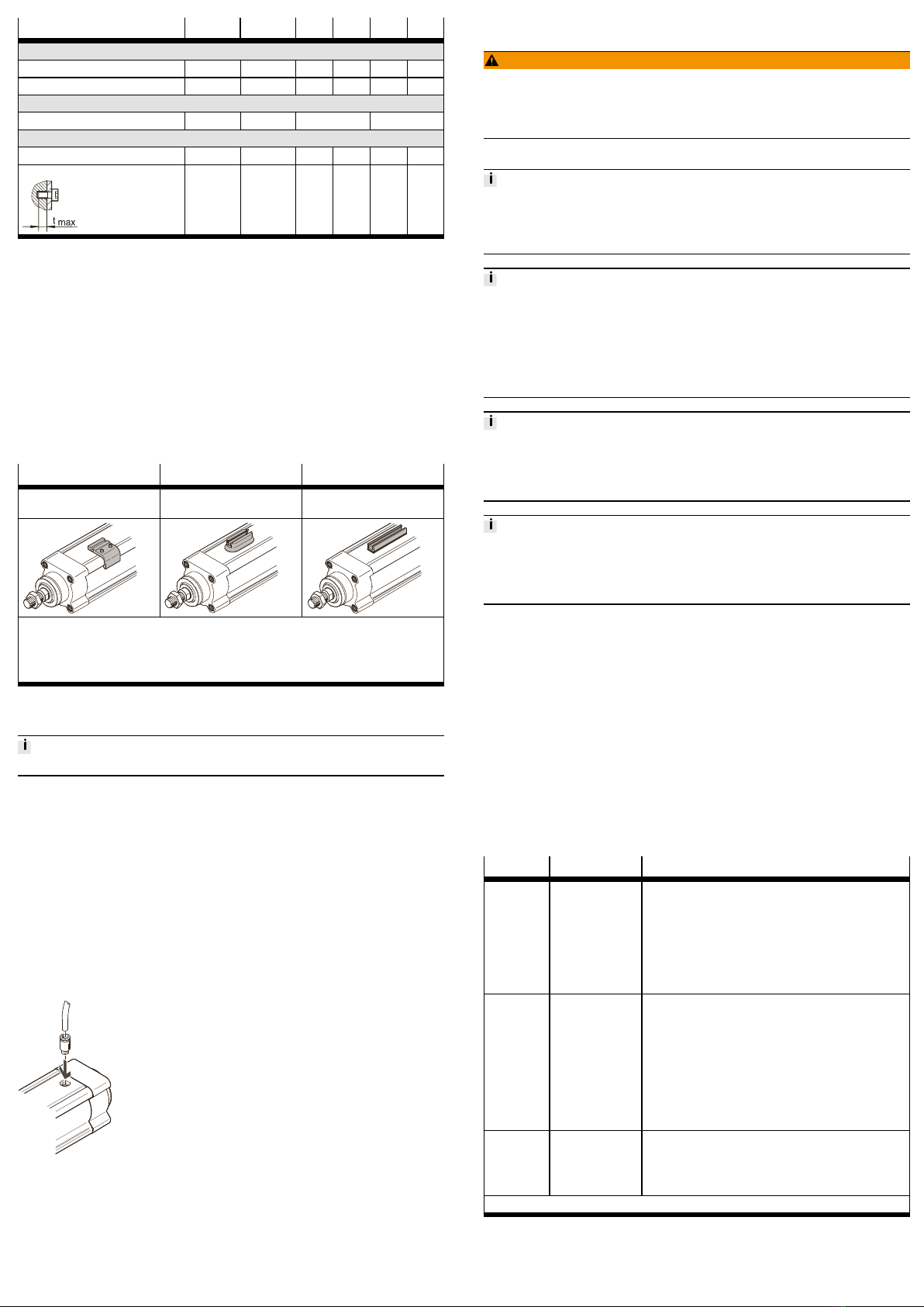
1. Remove protective cap.
2. Mount the screw fitting and connect the hose.
Fig. 4 Mount fitting (example: cylinder profile connection)
8 Commissioning
8.1 Safety
WARNING!
Risk of injury due to unexpected movement of components.
• Protect the positioning range from unwanted intervention.
• Keep foreign objects out of the positioning range.
• Perform commissioning with low dynamic response.
8.2 Performing Commissioning
When the motor is removed, the motor encoder loses its absolute reference to the
reference mark (e.g. by turning the motor drive shaft).
• Carry out a homing run after every motor mounting in order to establish the
absolute reference between the motor encoder and the reference mark.
Blockshaped acceleration profiles (without jerk limitation) can have the following
effects:
• High mechanical loads on the lead screw due to high force peaks.
• Overshooting effects during positioning.
• Swinging up of the entire system
Recommendation: Reduce high force peaks in the acceleration and deceleration
phases by using the jerk limitation.
Torque on the Piston Rod
During commissioning and operation, the piston rod may only be operated
without torque.
If external torques occur, an external guide must be used.
Running Noises During Operation
Identically constructed electric cylinders can generate different running noises
depending on the mode of operation, type of mounting, installation environment
and components.
Requirement
– Mounting of the drive system checked.
– Installation and wiring of the motor checked.
– No foreign objects in the movement space of the propulsion system.
– No exceeding of the max. permissible feed force and drive torque as a func
tion of acceleration, deceleration (e.g.stop function, quick stop), velocity,
moving mass and mounting position.
– No mechanical overload of the cylinder and dynamic setpoint deviation not
exceeded (e.g.overrunning the end position) due to force and torque peaks
or overshoot effects.
Limit overloads and overruns by jerk limitation, lower acceleration and decel
eration setpoints or optimised controller settings.
– Control and homing travel at reduced velocity, acceleration and deceleration
setpoints.
– No test drive to mechanical end stops.
– Software end positions ≥0.25 mm away from the mechanical stops.
Procedure Purpose Note
1. Check run Determine the dir
ection of travel of
the piston rod
– Direction of movement of piston rod (clockwise spindle):
– Retracting: Rotate cylinder drive shaft clockwise.
– Extending: Rotate cylinder drive shaft anticlock
wise.
– The direction of movement of the piston rod for positive
and negative position values depends on the mounting
position of the motor on the cylinder.
– Adapt a required reversal of direction of rotation via
parameters in the controller or controller.
2. Homing Determination of
the reference point
and adjustment of
the dimensional ref
erence system
– During the ini
tial startup
procedure
– After replace
ment of the
motor
Permissible reference points:
– Towards reference switch.
Travel at reduced velocity è 14 Technical data.
– Against the end position on the motor side.
Do not exceed maximum values
è Tab. 10 Speed and Energy in the End Positions.
Further information èInstruction manual of the drive system,
www.festo.com/sp.
3. Test run Checking the oper
ating conditions
Check application requirements:
– Piston rod travels through the complete travel cycle in
the specified time.
– The piston rod stops travel when a limit switch or soft
ware end positions are reached.
After a successful test run, the drive system is ready for operation.
Tab. 9 Commissioning Steps