manuals.online logo
Brands
  1. Home
  2. •
  3. Brands
  4. •
  5. Delta
  6. •
  7. Fan
  8. •
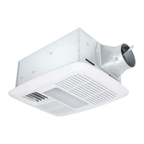
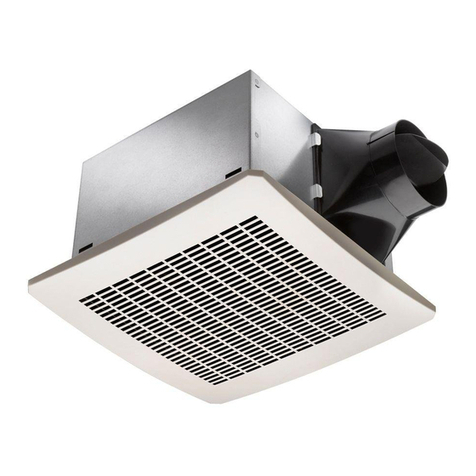
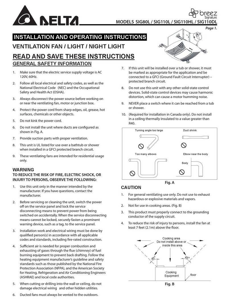
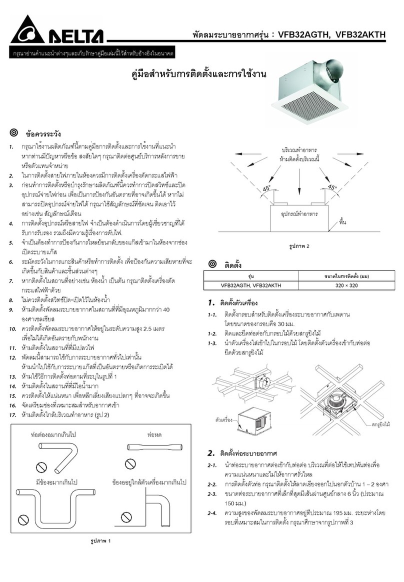
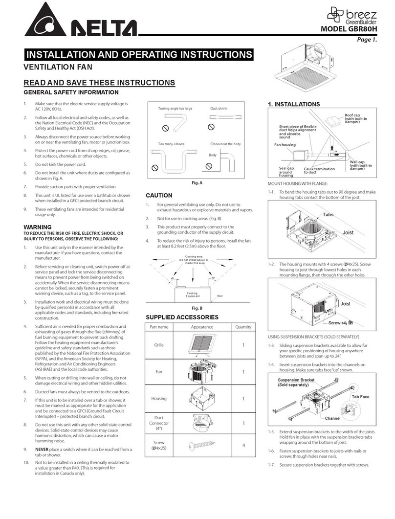
  9. Delta breez RAD80-DGL User manual

Delta breez RAD80-DGL User manual

1
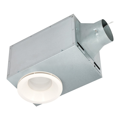
VENTILATION FAN
WITH LED LIGHT AND HEATER

Installation and Operating Instructions
IMPORTANT INSTRUCTIONS
When using electrical appliances, basic precautions
should always be followed to reduce the risk of fire,
electric shock, and injury to persons, including the
following:
1. Read all instructions before installing or using
this heater.
2. Extreme caution is necessary when heater fan

persons with disabilities or limitations.
3. Do not operate heater if it malfunctions.
Disconnect power at service panel and have
heater inspected by reputable electrician before
reusing.
4. Do not use outdoors.
5. To disconnect heater, turn controls to OFF
switch. Then, turn off the power to the heater
circuit at the main disconnect panel.
6. Do not insert or allow foreign objects to enter
any ventilation or exhaust opening as this may
cause an electric shock of fire, or damage the
heater.
7. To prevent a possible fire, do not block air
intakes or exhaust in any manner.
8. A heater has hot and arcing or sparking parts
inside. Do not use it in areas where gasoline,
paint, or flammable vapors or liquids are used or
stored.
9. Use this heater only as described in this
manual. Any other use not recommended by the
manufacturer may cause fire, electric shock or
injury to persons.
SAVE THESE INSTRUCTIONS
Read carefully before attempting to assemble,
install, operate or maintain the product described.
Protect yourself and others by observing all safety
information. Failure to comply with instructions

damage.
SAFETY INFORMATION
Please read and understand this entire manual
before attempting to assemble, operate or install
the product.
1. Follow all local safety and electrical codes as


2. This unit must be properly grounded.
3. Always disconnect the power supply prior to
servicing the fan, motor or junction box.
4. Do not bend or kink the power wires. Protect
from sharp edges, oil, grease, hot surfaces,
chemicals or other objects.
5. Do not install where the room air temperature

6. Do not install over a tub or mount in a shower
stall enclosure.
7. Do not use to exhaust hazardous or explosive
vapors.
8. Do not install in a cooking area.
9. Do not install this fan vertically in a wall.
10. Use this unit in the manner intended by the
manufacturer.
11. If you have any questions, please call the
manufacturer.
12. Installation work must be carried out by a

and safety codes including the rules for fire-
rated construction. For use in non-fire rated
installations only.
13. 
combustion and the exhaustion of gases through





and the local building code authorities.
14. Exercise care to not damage existing wiring
when cutting or drilling into walls or ceilings.
15. Fans should always be vented to the exterior
and in compliance with local codes.
16. Do not use this fan with any solid state control

controls may cause harmonic distortion, which
can cause a motor humming noise.
17. Prior to service or cleaning this unit, shut off
power supply at the panel and lock to prevent
the power from being turned on. If the panel
cannot be locked, clearly mark the panel with
a warning tag to prevent the power from being
turned on.
18. Do not install in a ceiling with insulation greater


19. Duct work should be installed in a straight line
with minimal bends.
20.Duct work size must be a minimum of the
discharge and should not be reduced. Reducing
the duct size can increase fan noise.
21. This ventilating bath fan is intended for

22. Never place a switch where it can be reached
from a tub or shower.
23.Make sure that the electric service supply

24. Always disconnect the power source before
working on or near the unit.
25. This unit is designed and tested to be a
supplemental heater for use with a timer or a
switch. It is not intended to be used as a primary
source of heat, or controlled by a thermostat.
26. 
or unbalanced impellers, keep drywall spray,
construction dust, etc., off power unit.
27. Provide a separate 15 AMP circuit.
28.This product is designed for ceiling installation
only. Do not mount this product in a wall.
29.Install in ceiling only, at least 6 in. from any wall.
30.For greatest efficiency, adjust heater grille
directly toward tub or shower area. Avoid
directing toward walls or windows.
31. 
floor.
32.Do not install the unit where ducts are
confugured as shown in Fig. A.
33.
Fig. A
Turning angle too large
Too many elbows
Duct shrink
Elbow near the body
Body
Minimum 18 in.
PREPARATION






Carefully remove unit from carton.
Before installation, provide inspection and future
maintenance access at a location that will not
interfere with installation work.
Check area above installation location to be sure
that wiring can run to the planned location and
that duct work can be run. Make sure the area is
sufficient for proper ventilation.
You may need the help of a second person to
install this fan: one person on the attic side and
one on the room side.
Note: Installations may vary depending on how the

for the installation of your bath fan are not all
included.

improvement or hardware store.
Proper insulation around the fan to minimize
building heat loss and gain.
The fan will operate most efficiently when
located where the shortest possible duct run and
minimum number of elbows will be needed.
Use a roof cap or wall cap that has a built-in
damper to reduce backdrafts.

Please contact Delta Breez customer service
and consult with a licensed electrician for
compatibility.
Determine the distance between your joist.

center joists
16.0 inches
19.2 inches
24.0 inches

dimensions provided below. Be careful to cut hole
exactly. If hole is too big, the fan grille will not hide
it.
Joist
2
PACKAGE CONTENTS
PART  APPEARANCE QTY
1Fan Body 1
2

Assembly
For model

1
2

Assembly
For model
RAD80ELED
1
3

Bracket
I2
4

Bracket
II 2
× 4

× 8

A
B
HARDWARE CONTENTS

DIMENSION REQUIREMENTS
Ceiling

Ceiling

Ceiling

  






  
ASSEMBLY INSTRUCTIONS

Carefully remove unit from carton. Remove the foam
in the housing. Refer to the Package Contents list
on page 1 to verify that all parts are present.
Installing the unit
Installing the fan body in an existing building

above the planned installation location and existing
duct and wiring.
Check area above installation
location to ensure that:
• Duct work can be run and the area is sufficient
for proper ventilation.
• Wiring can be run to the planned location.
• No wiring or other obstructions can interfere
with installation.

• To reduce the risk of fire, do not store or use
gasoline or other flammable vapors and liquids
in the vicinity of the heater.
INSTALLATION
1. Mounting the fan body between the joists
a. Insert either the 12 in. suspension brackets
4or 14 in. suspension brackets 3to the
duct side and back of the fan body 1,
depending on the distance between the
joists.
b. Insert the fan body 1between joists. Make
sure the fan body is level and perpendicular
with the joist, and flush with ceiling surface.
c. Allow for thickness of the ceiling board used
in your application. Fan body 1should be
flush with ceiling board.
d. 
the wood screws B.
e. 
1with the wood screws A.
f. Remove tap before connecting the duct as

Hardware
A
B
1
34
A
B


2. Connecting the duct
All ducting must comply with local
and national building codes.
a. Insert the duct into the duct connector and
tape all duct work connections to make them
secure and air tight.
2
3. Remove the fan junction box cover a. Using

fan wires as shown in the wiring diagram on
page 3. Wire connections are as follows: black
to live switch wire, white to neutral, green to
ground. Reattach fan junction box cover c.
a
b
c
3
4. Completing the Installation
a. Check the plug from the fan into the
receptacle marked “Vent”.
Check the plug from the heating unit into the

Vent
Light
Heat
For model
RAD80ELED only

2 3
b. Plug the Light Connector into the receptacle

LED Cable
Plug the LED
cable into the
LED driver.

5. Attach grille 2by pinching mounting springs a
and insert into narrow rectangular slots in fan
body.
2
a
Spring
Slots
5
WIRING INSTRUCTIONS

• Make sure power is switched off at service panel
before starting installation.
• All electrical connections must be made in
accordance with local codes, ordinances, or
national electrical code. If you are unfamiliar with
methods of installing electrical wiring, secure the
services of a qualified electrician.

This unit must be wired on a separate 15 amp
circuit.
• If your house wires do not match these colors,
you must determine what each house wire
represents before connecting and you may need
to consult an electrical contractor to determine
this safely.
1. Follow all local electrical and safety codes.
2. Never place a switch where it can be reached
from a tub shower.
3. 
power wires to fan wires.
4. 2
may be used for branch-circuit wiring. Each

switch to operate independently.
5. For supply connections, use wire rated for at


I
I
I
I
I I
I I
I I
I
I
I
I
I
I
Model: RAD80ELED
I I
I
I
I
I
I
I
I
III
I
II
I
I I
I I
I
OPERATING INSTRUCTIONS

This unit must be properly installed before it is used.
Follow instructions for cleaning, user-maintenance
and operations recommended by the manufacturer,
such as lubrication or non lubrication. Any other
servicing should be performed by an authorized
service representative.
1. Turn on the light switch to turn on the LED light.

2. Turn on the vent switch to operate the fan mode.
3. Turn on the heat switch to operate the heater
mode.
CARE AND MAINTENANCE

maintenance should be done at least once a year.
• Never use solvents, thinner or harsh chemicals
when cleaning the fan.
• Do not allow water to enter the motor, heater
and LED module.
• Do not immerse metal parts in water.
• Do not immerse resin parts in water over 140º
Fahrenheit.
• Turn off power source. Review all safety
precautions.
1. 
2
a
1
2. Remove grille assembly 2.

1
2
LED Cable
Unplug the LED
cable From the
LED driver.
2
3. Remove dust and dirt from fan body 1with a
vacuum cleaner.
Vacuum
cleaner
1
3
4
TROUBLESHOOTING
PROBLEM POSSIBLE CAUSE CORRECTIVE ACTION
The fan is not turning ON 1. Power off
2. Faulty switch
3. Faulty wire connection
1. Make sure power supply is on.
2. Test or replace switch.
3. Check wire in switch box.
The fan seems louder than it
should
1. CFM too great
2. Damper not working properly or damaged
3. Bend in duct too close to fan discharge
4. Fan discharge reduced to fit smaller duct
5. Fan body not securely attached
1. Be sure the CFM rating on the fan matches the size of your room.
2. Check damper to ensure it is opening and closing properly. If the damper

3. Be sure you do not have any sharp bends in duct closer than 18 in. to the
fan discharge.
4. Use recommended size ducting to reduce fan noise.
5. Be sure the fan is securely attached to your ceiling joists.
The fan is not clearing the room 1. Insufficient intake airfow within room
2. Insufficient CFM
1. Be sure a door or window is slightly ajar or opened to allow airflow. The
fan is not able to draw air out of the room without enough airflow to
draw in from.
2. Be sure the CFM rating on the fan matches the requirements for your
room size.
The light is not turning ON

1. Power off
2. Faulty switch
3. Faulty wire connection
1. Make sure power supply is on.
2. Test or replace switch.
3. Check wire in switch box.
The heater is not heating than it
should
1. Faulty switch
2. Faulty wire connection
3. Filter is not clean
1. Test or replace switch.
2. Check wire in switch box.
3. Remove dust from filter.
DIMENSIONS Unit: Inches
 Model: RAD80ELED
WARRANTY



Limitations and Exclusions
1. During the warranty period, a replacement for any defective product will be supplied free of charge for installation by the consumer. The warranty
provided herein does not cover charges for labor or other costs incurred in the troubleshooting, repair, removal, and installation service.
2. All returns of defective parts or products must include the product model number, and must be made through an authorized Delta Electronics
distributor. Authorized returns must be shipped prepaid. Repaired or replacement products will be shipped by Delta Electronics F.O.B. shipping point.
3. Delta Electronics shall not be liable for any indirect, incidental, consequential, punitive, or special damages arising out of or in connection with

4. This warranty does not extend to fluorescent lamp starters and tubes.
5. The warranty does not cover if user does not comply with manufacturer’s installation manual.
6. To qualify for warranty service, you must notify Delta Electronics at the address or telephone number below.
7. Delta Electronics shall have no liability to the original owner-user with respect to any defect caused by abuse, misuse, neglect, improper
transportation or storage, improper testing, improper installation, improper operation, improper use, improper maintenance, improper repair, improper
alteration, improper modification, tampering or accident of products or parts thereof, or unusual deterioration or degradation of products or parts
thereof due to a physical environment beyond the requirement of products' specifications.
Address: 46101 Fremont Boulevard, Fremont, CA 94538



www.deltabreez.com
PRODUCT SPECIFICATIONS
Model No. Air flow
    Power

Duct Diameter
  Main Light Output
 80 1.5 120 60 1314 4 10.1 -
RAD80ELED 80 1.5 120 60 1327 4 11.6 900 Lumens


Note: Design and specifications subject to change without notice.
10
"
8
"
4.0
"
16 "
14 "
5 
1 "
1
"
10
"
4.0
"
16 " 5 
1 "
1
"
8
"
14 "

This manual suits for next models

1

Other Delta Fan manuals

Delta VFB17AXTH User manual

Delta

Delta VFB17AXTH User manual

Delta KHB1248EHS User manual

Delta

Delta KHB1248EHS User manual

Delta breez Slim SLM100 User manual

Delta

Delta breez Slim SLM100 User manual

Delta GBR80HL User manual

Delta

Delta GBR80HL User manual

Delta VFA15ADTH2 User manual

Delta

Delta VFA15ADTH2 User manual

Delta BREEZ VCA523 Series User manual

Delta

Delta BREEZ VCA523 Series User manual

Delta VFB080C4LED2-A User manual

Delta

Delta VFB080C4LED2-A User manual

Delta Breez ITG50 User manual

Delta

Delta Breez ITG50 User manual

Delta breez Slim SLM80-110-C User manual

Delta

Delta breez Slim SLM80-110-C User manual

Delta BreezIntegrity ITG80 User manual

Delta

Delta BreezIntegrity ITG80 User manual

Delta SLM50 User manual

Delta

Delta SLM50 User manual

Delta Breez GreenBuilder GBR50 User manual

Delta

Delta Breez GreenBuilder GBR50 User manual

Delta FRS200/VDB200F6D1 User manual

Delta

Delta FRS200/VDB200F6D1 User manual

Delta Breez GBR50L User manual

Delta

Delta Breez GBR50L User manual

Delta Breez Integrity ITG100 User manual

Delta

Delta Breez Integrity ITG100 User manual

Delta BREEZ 90LED-REC-ADJ User manual

Delta

Delta BREEZ 90LED-REC-ADJ User manual

Delta BreezSlim SLM50-110-C User manual

Delta

Delta BreezSlim SLM50-110-C User manual

Delta Breez GreenBuilder GBR50 User manual

Delta

Delta Breez GreenBuilder GBR50 User manual

Delta breez Smart SMT150-200 User manual

Delta

Delta breez Smart SMT150-200 User manual

Delta BreezGreenBuilder GBR80LED User manual

Delta

Delta BreezGreenBuilder GBR80LED User manual

Delta breez 110LED-ADJ User manual

Delta

Delta breez 110LED-ADJ User manual

Delta VFB080C4L1 User manual

Delta

Delta VFB080C4L1 User manual

Delta AirEye Ion User manual

Delta

Delta AirEye Ion User manual

Delta Breez Slim SLM80-110 User manual

Delta

Delta Breez Slim SLM80-110 User manual

Popular Fan manuals by other brands

Casablanca M6006-01 Installation and operation manual

Casablanca

Casablanca M6006-01 Installation and operation manual

Broan 355SOBK manual

Broan

Broan 355SOBK manual

Koenic KTF 121 user manual

Koenic

Koenic KTF 121 user manual

Taurus Alpatec FRESKO 4B manual

Taurus Alpatec

Taurus Alpatec FRESKO 4B manual

EDM 33949 instruction manual

EDM

EDM 33949 instruction manual

Caladair PYROSTAR F400-120 Installation and commissioning manual

Caladair

Caladair PYROSTAR F400-120 Installation and commissioning manual

ACME VQ80 quick start guide

ACME

ACME VQ80 quick start guide

Rowenta VU211 Series instruction manual

Rowenta

Rowenta VU211 Series instruction manual

System air KBR 315D2 IE2 Installation and operating instructions

System air

System air KBR 315D2 IE2 Installation and operating instructions

Ebmpapst W2D250-CA06-52 operating instructions

Ebmpapst

Ebmpapst W2D250-CA06-52 operating instructions

Ebmpapst D4D225-CC01-02 operating instructions

Ebmpapst

Ebmpapst D4D225-CC01-02 operating instructions

Craftmade Champion CHP609 installation guide

Craftmade

Craftmade Champion CHP609 installation guide

Ebmpapst R4E250-AH01-05 operating instructions

Ebmpapst

Ebmpapst R4E250-AH01-05 operating instructions

Ebmpapst W2G115-AD15-13 operating instructions

Ebmpapst

Ebmpapst W2G115-AD15-13 operating instructions

Ebmpapst W2S130-AB25-10 operating instructions

Ebmpapst

Ebmpapst W2S130-AB25-10 operating instructions

Scarlett Comfort SC-DF111S06 instruction manual

Scarlett

Scarlett Comfort SC-DF111S06 instruction manual

Ebmpapst S3G710-AU21-01 operating instructions

Ebmpapst

Ebmpapst S3G710-AU21-01 operating instructions

Ebmpapst W1G180-AB31-39 operating instructions

Ebmpapst

Ebmpapst W1G180-AB31-39 operating instructions

manuals.online logo
manuals.online logoBrands
  • About & Mission
  • Contact us
  • Privacy Policy
  • Terms and Conditions

Copyright 2025 Manuals.Online. All Rights Reserved.