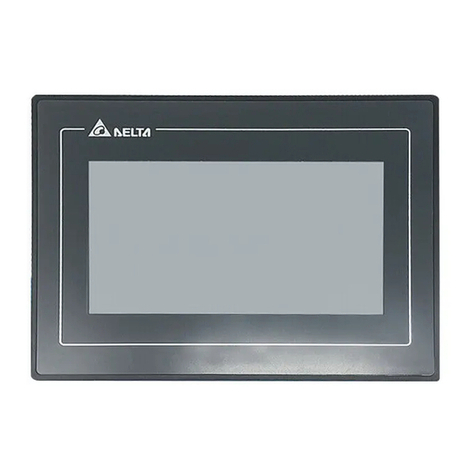
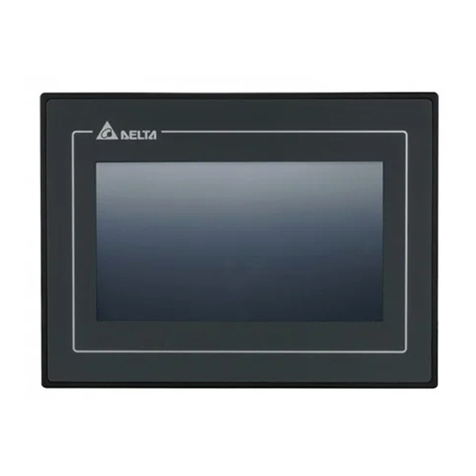
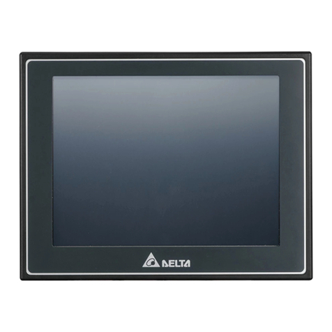
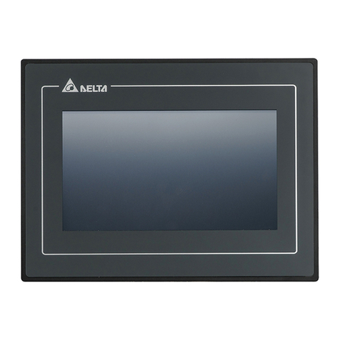
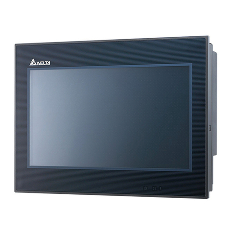
Delta TP70P-211LC1T User manual

*We reserve the right to change the information in this catalogue without prior notice.
Industrial Automation Headquarters
Taiwan: Delta Electronics, Inc.
Taoyuan Technology Center
No.18, Xinglong Rd., Taoyuan District,
Taoyuan City 33068, Taiwan
TEL:-3-362-6301 / FAX:-3-371-6301
Asia
China: Delta Electronics (Shanghai)Co., Ltd.
No.182 Minyu Rd., Pudong Shanghai, P.R.C.
-21-6872--21-6872-
Customer Service: 400-820-
Japan: Delta Electronics (Japan), Inc.
Industrial Automation Sales Department
2-1-14 Shibadaimon, Minato-ku
-0012
-3---3--
Korea: Delta Electronics (Korea), Inc.
--gu,
-2---2--
Singapore: Delta Energy Systems (Singapore)Pte Ltd.
-
-6747--6744-
India: Delta Electronics (India)Pvt. Ltd.
-124--124-
Thailand: Delta Electronics (Thailand)PCL.
(E.P.Z),
Pattana 1 Rd., T.Phraksa, A.Muang,
Samutprakarn 10280, Thailand
--2800 / FAX66-2-2827
Australia: Delta Electronics (Australia)Pty Ltd.
Mail: IA.au@deltaww.com
Americas
USA: Delta Electronics (Americas)Ltd.
--767---767-
Brazil: Delta Electronics Brazil Ltd.
-12---12--237
Mexico: Delta Electronics International Mexico S.A. de C.V.
--3603-
EMEA
EMEA Headquarters: Delta Electronics (Netherlands)B.V.
Sales: Sales.IA.EMEA@deltaww.com
Marketing: Marketing.IA.EMEA@deltaww.com
Technical Support: iatechnicalsupport@deltaww.com
Customer Support: Customer-Support@deltaww.com
Service: Service.IA.emea@deltaww.com
(0)
BENELUX: Delta Electronics (Netherlands)B.V.
(0)
DACH: Delta Electronics (Netherlands)B.V.
-
(0)
France: Delta Electronics (France)S.A.
Mail: Sales.IA.FR@deltaww.com
(0)
Iberia: Delta Electronics Solutions (Spain)S.L.U
(0)
Mail: Sales.IA.Iberia@deltaww.com
Italy: Delta Electronics (Italy)S.r.l.
(CO)
Mail: Sales.IA.Italy@deltaww.com
Russia: Delta Energy System LLC
Mail: Sales.IA.RU@deltaww.com
Turkey: Delta Greentech Elektronik San. Ltd. Sti. (Turkey)
-A
Mail: Sales.IA.Turkey@deltaww.com
MEA: Eltek Dubai (Eltek MEA DMCC)
Jumeirah Lakes Towers, Dubai, UAE
Mail: Sales.IA.MEA@deltaww.com
(0)
TP-0148620-02
www.deltaww.com
Digitized Automation for a Changing World
TP70P-211LC1T / TP04P-20EXL1T
Operation Manual

TP70P-211LC1T/TP04P-20EXL1T
Operation Manual
REVISION HISTORY
Version Revision Date
1st The first version was published. 2019/2/20
2nd Specification correction 2019/4/10
3rd
1.Update information of TP04P CPU concerning panel
waterproof rating and altitude ranges in section 2.2.2.
2.Update information of response time and max. output
frequency in section 2.2.3.
3.Update the content in section 4.1 Installation.
4.Update the device range of X/Y and information of T/C
devices in section 5.1.
5.Update the content concerning D1022/D4323/D4333 in
section 5.2.
2022/10/06


i
TP70P-211LC1T/TP04P-20EXL1T
Table of Contents
Chapter 1 Introduction
1.1 Overview ...........................................................................................1-2
1.2 Related Manuals ................................................................................1-2
1.3 Model Descriptions ............................................................................1-3
1.3.1 TP70P-211LC1T ............................................................................. 1-3
1.3.2 TP04P-20EXL1T ............................................................................. 1-4
1.3.3 Inputs and Outputs........................................................................ 1-4
Chapter 2 Specifications and Functions
2.1 Profile and Arrangement of Terminals...............................................2-2
2.1.1 TP70P-211LC1T ............................................................................. 2-2
2.1.2 TP04P-20EXL1T ............................................................................. 2-6
2.2 Specifications and Functions ...........................................................2-10
2.2.1 Functional Specifications............................................................... 2-10
2.2.1.1 TP70P-211LC1T.......................................................................... 2-10
2.2.1.2 TP04P-20EXL1T .......................................................................... 2-11
2.2.2 Electrical Specificaitons................................................................. 2-12
2.2.3 Digital Input/Output Specifications................................................. 2-13
2.2.4 Analog Input/Output Specifications ................................................ 2-14
2.2.4.1 Electrical Specifications for Analog Output Terminals....................... 2-14
2.2.4.2 Electrical Specifications for Temperature / Current / Analog Input
Terminals.................................................................................... 2-14
2.2.4.3 Electrical Specifications for Loadcell Terminals................................ 2-15
2.2.4.4 TP70P-211LC1T Electrical Specifications for Analog Voltage / Current
Input Terminals........................................................................... 2-16
2.2.4.5 TP04P-20EXL1T Electrical Specifications for Analog Voltage / Current
Output Terminals......................................................................... 2-16
Chapter 3 Interface Introduction
3.1 TP70P-211LC1T Operational Interface .............................................. 3-2
3.1.1 Load Cell Setup ............................................................................. 3-3
3.1.2 Load Cell Calibration Process........................................................... 3-5
3.1.3 Load Cell Full Screen Display........................................................... 3-7
3.1.4 Analog I/O .................................................................................... 3-9

ii
3.1.5 Digital I/O....................................................................................3-10
3.1.6 System Setup...............................................................................3-11
3.2 TP04P-20EXL1T Operational Interface .............................................3-12
3.2.1 Load Cell Setup ............................................................................3-13
3.2.2 Load Cell Calibration Process..........................................................3-14
3.2.3 Load Cell Full Screen Display..........................................................3-17
Chapter 4 Installation and Wiring
4.1 Installation........................................................................................ 4-2
4.2 Wiring ............................................................................................... 4-3
4.2.1 Wiring Power................................................................................. 4-3
4.2.2 Wiring Digital Input Terminals ......................................................... 4-5
4.2.3 Wiring Digital Output Terminals ....................................................... 4-5
4.2.4 Wiring Analog Input Terminals......................................................... 4-6
4.2.5 Wiring Analog Voltage / Current Output Terminals.............................. 4-7
4.2.6 Wiring Analog Current Output Terminals........................................... 4-8
4.2.7 Mixed Analog Input Terminals.......................................................... 4-9
4.2.8 Wiring Load Cell Terminals.............................................................4-10
4.2.9 Definitions of RS-485 Ports ............................................................4-11
Chapter 5 Devices
5.1 Devices.............................................................................................. 5-2
5.2 Special Data Registers....................................................................... 5-4
5.3 Special Auxiliary Relay .................................................................... 5-12
5.4 Special Data Registers Specific for TP Series...................................5-21

1-1
Chapter 1 Product Introduction
Table of Contents
1.1 Overview ............................................................................... 1-2
1.2 Related Manuals .................................................................... 1-2
1.3 Model Descriptions ................................................................ 1-3
1.3.1 TP70P-211LC1T ...................................................................1-3
1.3.2 TP04P-20EXL1T ...................................................................1-4
1.3.3 Inputs and Outputs ..............................................................1-4
1

TP70P-211LC1T/TP04P-20EXL1T Operation Manual
1-2
_1
1.1 Overview
This manual introduces the product specifications, wiring, functions, interface, corresponding registers, operation and so
forth for TP70P-211LC1T and TP04P-20EXL1.
1.2 Related Manuals
The related manuals for TP70P-211LC1T and TP04P-20EXL1Tare listed below.
The installation instructions for TP70P-211LC1T and TP04P-20EXL1T.
An installation instruction is enclosed in the package, introducing important information for the first time user.
TPEditor User Manual
This introduces the installation, configuration, and operation of the TPEditor software.
ISPSoft User Manual
This introduces the use of the ISPSoft software, programming language (Ladder, IL, SFC, FBD, and ST), POUs, and
tasks.

Chapter 1 Product Introduction
1-3
1__
1.3 Model Descriptions
1.3.1 TP70P-211LC1T
Type
7-inch Touch Panel HMI with Built-in PLC
Model Name
TP70P-211LC1T
Description
Digital
Input / Output
24VDC, 5mA, 17 inputs
12 ~ 24VDC, 0.5A/output, 2.5A/COM, Transistor-
T (sinking) (NPN), 24
outputs
Analog Output 4 analog channel; current 0 ~ 20mA / 4 ~ 20mA
Analog / Temperature
Measurement Input
2 input channel; 0 ~ 5V, 0 ~ 10V, 0 ~ 50mV, 0 ~ 20mA, 4 ~ 20mA; applicable
sensors: Pt100 / JPt100 / Pt1000 / Ni100 / Ni1000 / LG-Ni1000 / Cu50 /
Cu100; 16-bit resolution
Load Cell Input
1-channel, 4-wire/6-wire load cell sensor
Highest precision: 0.01%。ADC Resolution: 24 bits
Conversion time: selectable 2.5 ~ 400ms
Variable excitation voltage: 2 ~ 9.5V/250mA
Communication Port Isolated USB (COM1) & Isolated RS-485 (COM2/COM3)

TP70P-211LC1T/TP04P-20EXL1T Operation Manual
1-4
_1
_1
1.3.2 TP04P-20EXL1T
Type
Text Panel HMI with Built-in PLC
Model Name
TP04P-20EXL1T
Description
Digital
Input / Output 24VDC, 5mA, 9 inputs
12-24VDC, 0.5A/output, 2.5A/COM, Transistor-T (sinking) (NPN), 16 outputs
Analog Input -10 ~ +10V, -20mA ~ +20mA, 4 ~ 20mA, 4 inputs; 12-bit resolution
Analog Output 4 analog channel; current 0 ~ 20mA/ 4 ~ 20mA
2 analog channel; voltage: -10 ~ +10V; current: 0mA~ 20mA / 4 ~ 20mA
Analog / Temperature
Measurement Input
2 input channel; 0 ~ 5V, 0 ~ 10V, 0 ~ 50mV, 0 ~ 20mA, 4 ~ 20mA; applicable
sensor: Pt100 / JPt100 / Pt1000 / Ni100 / Ni1000 / LG-Ni1000 / Cu50 /
Cu100; 16-bit resolution
Load Cell Input
1-channel, 4-wire/6-wire load cell sensor
Highest precision: 0.01%。ADC Resolution: 24 bits
Conversion time: selectable 2.5 ~ 400ms
Variable excitation voltage: 2 ~ 9.5V/250mA
Communication Port Isolated USB (COM1) & Isolated RS-485 (COM2/COM3)
1.3.3 Inputs and Outputs
Models Digital Input
Digital
Output
Analog Input
Analog
Output
Analog /
Temperature
Measurement
Input
Load Cell
Input Output Type
TP70P-211LC1T 17 24 - 4 2AX 1LC
Sinking
(NPN)
TP04P-20EXL1T 9 16 4 6 2AX 1LC
Sinking
(NPN)

2- 1
2
Chapter 2 Specifications and Functions
Table of Contents
2.1 Profile and Arrangement of Terminals ............................................... 2-2
2.1.1 TP70P-211LC1T ............................................................................ 2-2
2.1.2 TP04P-20EXL1T ............................................................................ 2-6
2.2 Specifications and Functions ........................................................... 2-10
2.2.1 Functional Specifications .............................................................. 2-10
2.2.1.1 TP70P-211LC1T ......................................................................... 2-10
2.2.1.2 TP04P-20EXL1T ......................................................................... 2-11
2.2.2 Electrical Specificaitons................................................................ 2-12
2.2.3 Digital Input/Output Specifications ................................................ 2-13
2.2.4 Analog Input/Output Specifications................................................ 2-14
2.2.4.1 Electrical Specifications for Analog Output Terminals....................... 2-14
2.2.4.2 Electrical Specifications for Temperature / Current / Analog Input
Terminals .................................................................................. 2-14
2.2.4.3 Electrical Specifications for Loadcell Terminals ............................... 2-15
2.2.4.4 TP70P-211LC1T Electrical Specifications for Analog Voltage / Current
Input Terminals .......................................................................... 2-16
2.2.4.5 TP04P-20EXL1T Electrical Specifications for Analog Voltage / Current
Output Terminals ........................................................................ 2-16

TP70P-211LC1T/TP04P-20EXL1T Operation Manual
2- 2
_ 2
2.1 Profile and Arrangement of Terminals
2.1.1 TP70P-211LC1T
Profile
87.7
205.6
142.6
Unit: mm
Opening Dimensions
The opening size should be within the tolerance limits of ±0.1mm to ensure a waterproof and dustproof
installation.
127.1
~
128.0
190.1~191.0
0.5~4.0
Unit: mm

Chapter 2 Specifications and Functions
2- 3
2__
Arrangement of Terminals
Terminals on the I/O board
①
1
2
3 4
C2
Y20
Y21
Y22
Y23
Y24
Y25
Y26
Y27
•
②
S/S2
X20
•
IO1
IO2
IO3
IO4
AGND
AGND
•
③
•
•
SLD
SLD
SEN-
SEN+
SIG-
SIG+
EXC-
EXC+
④
L1+
I1+
L1-
AGND
L2+
I2+
L2-
AGND
FG
•

TP70P-211LC1T/TP04P-20EXL1T Operation Manual
2- 4
_ 2
Terminals on the drive board
⑤
5
6
7
8
⑦
S/S0
C0
X0
Y0
X1
Y1
X2
Y2
X3
Y3
X4
Y4
X5
Y5
X6
Y6
X7
Y7
•
•
⑥⑧
S/S1
C1
X10
Y10
X11
Y11
X12
Y12
X13
Y13
X14
Y14
X15
Y15
X16
Y16
X17
Y17
•
•

Chapter 2 Specifications and Functions
2- 5
2__
Descriptions
9
10
11
12
13
Number
Description
⑨Reset button
⑩RUN/STOP switches
⑪USB port for programs to be uploaded or downloaded
⑫RS-485 communications ( two sets of RS-485 communicaiton interfaces)
⑬DC power

TP70P-211LC1T/TP04P-20EXL1T Operation Manual
2- 6
_ 2
2.1.2 TP04P-20EXL1T
Profile
82.4
175.8
108.6
Unit: mm
Opening Dimensions
The opening size should be within the tolerance limits of ±0.1mm to ensure a waterproof and dustproof
installation.
95.5
~
97.0
162.7~164.0
0.5~4.0
Unit: mm

Chapter 2 Specifications and Functions
2- 7
2__
Arrangement of Terminals
Terminals on the I/O board
①
1
2
34
C2
Y20
Y21
Y22
Y23
Y24
Y25
Y26
Y27
•
②
S/S2
X20
•
IO1
IO2
IO3
IO4
AGND
AGND
•
③
•
•
SLD
SLD
SEN-
SEN+
SIG-
SIG+
EXC-
EXC+
④
L1+
I1+
L1-
AGND
L2+
I2+
L2-
AGND
FG
•

TP70P-211LC1T/TP04P-20EXL1T Operation Manual
2- 8
_ 2
Terminals on the drive board
⑤
5
6
7
8
⑦
S/S0
C0
X0
Y0
X1
Y1
X2
Y2
X3
Y3
X4
Y4
X5
Y5
X6
Y6
X7
Y7
•
•
⑥⑧
V0+
V3+
V0-
V3-
I0
I3
V1+
FE
V1-
V4
I1
I4
V2+
AG
V2-
V5
I2
I5
FE
AG

Chapter 2 Specifications and Functions
2- 9
2__
Descriptions
9
10
11
12
13
14
Number
Description
⑨USB port for programs to be uploaded or downloaded
⑩RUN/STOP switches
⑪DC power
⑫RS-485 communications ( two sets of RS-485 communicaiton interfaces)
⑬Reset button
⑭Slot for a program card

TP70P-211LC1T/TP04P-20EXL1T Operation Manual
2- 10
_ 2
2.2 Specifications and Functions
2.2.1 Functional Specifications
2.2.1.1 TP70P-211LC1T
Model
Specifications
TP70P-211LC1T
Display
Screen/Color
7” TFT LCD (65535 colors)
Resolution
800×480 pixels
Backlight type LED backlight (It has a lifespan of 20,000 hours at a temperature of 25℃)
Display area
Width × Height = 154 × 85 (Unit: mm); 7 inches (diagonal)
USB (COM1)
USB port for programs to be uploaded
or downloaded
Transmission: Virtual communication port
Data length: 7 bits or 8 bits
Stop bit: 1 bit or 2 bits
Parity check: None/Odd/Even
Transmission rate: 9,600 bps~115,200 bps
USB port: Type B USB connector
Isolated communication
RS-485
(Extension
Communicaiton
Ports)
COM2
(supporting PLC
mode)
COM3
(supporting TP
mode)
Data length: 7 bits or 8 bits
Stop bit: 1 bit or 2 bits
Parity check: None/Odd/Even
Transmission rate: 9,600 bps~115,200 bps
Connector: Male DB-9 connector
Isolated communication
Downloading and Monitoring
Programs can be downloaded to TP via a virtual communication port of TP.
PLC Program Capacity
4 K steps
Screen Capacity
4 Mbytes
This manual suits for next models
1
Table of contents
Other Delta Touch Panel manuals

Delta
Delta DOP-103WQ User manual

Delta
Delta DOP-107EG User manual

Delta
Delta DOP-B10 Series User manual

Delta
Delta DOP-107H User manual

Delta
Delta DOP-A User manual

Delta
Delta TP04G-AL User manual

Delta
Delta DOP-W127B User manual

Delta
Delta DOP-110IS User manual

Delta
Delta DIAVH-PPC193100 User manual

Delta
Delta DIAVH-IPC003100 User manual
Popular Touch Panel manuals by other brands

Beckhoff
Beckhoff CP72 Series Installation and operating instructions

Elo TouchSystems
Elo TouchSystems SW602681 Quick installation guide

Brainlab
Brainlab 17902 System and Technical User Guide

promethean
promethean ActivPanel Install & user's guide

Janz Tec
Janz Tec emVIEW-7/RPI3 Hardware manual

Omron
Omron K3HB manual