Dension ice-Link: Plus User manual

Dension ice>Link Install
2000 540i with DSP
No Navigation
Dension iceLink Plus / Ashtray Installation
IMPORTANT- PLEASE READ
The following iceLink Plus install can be performed fairly easily with some basic tools.
My car does not have the access opening from the trunk to the back seat; however, 5 series cars
with access are not affected in a major way.
-----IMPORTANT TIPS -----
READ THROUGH THE ENTIRE INSTALLATION GUIDE BEFORE
PERFORMING THIS INSTALLATON! EDITS AND UPDATES WERE ADDED!
READING FIRST WILL HELP YOU UNDERSTAND WHY THE UPDATES/ EDITS WERE MADE AND
HOPEFULLY KEEP YOU FROM MAKING A TIME WASTING MISAKE.
BEFORE WE GO…
In your excitement to get you new toy installed and working,
you will have the tendency to move very quickly…DON’T!
The best advice I can offer –
TAKE YOUR TIME -- THIS IS NOT THAT HARD OF AN INSTALL!
LEGAL STUFF
Author assumes no responsibility for damage resulting from the following installation procedure.
This guide was written as a reference source only.

Dension ice>Link Install
2000 540i with DSP
No Navigation
Installation Time – (1) Person
10 hours*
* It should be noted this was the first interior modification I have performed since owning the car. I suspect more
experienced BMW owners could perform this operation much quicker.
Cost(s)
$283.00
Tools
Screw Drivers (Flat / Philips)
Dremel Tool –Sanding and Cutting attachments. (See note below)
Bench Grinder
Needle Nose Pliers
Side Cutters
Electrical Tape
Duck Tape – I can not recommend the “Duck Tape” brand of tape. I purchased a new roll less than one month ago
and could not get it hold! I found an off brand in my garage that worked flawlessly.
Xacto Knife
Socket Set – 1/4” and 1/2” Ratchet
Sockets – 8mm / 10mm
Shop Light(s)
Pre-Installation Notes & Tips
During the steps, if a specific attachment for the Dremel Tool was used I will explain its description the best I can
and/or supply photos. I borrowed a friends Dremel tool so I am not sure of the proper naming of the exact cutting and
sanding attachments. Looking at the photos, studying the installation instructions and using your best judgment will
guide you. For specific questions or problems, just post them on the forum and I will try to answer.
Store all related parts, screws, etc. in separate Zip Lock bags. Another good idea (one I should have done) is to label the
bags.
Setup one playlist on the iPod before starting installation.
My car does not have the access opening from the trunk to the back seat; however, 5 series cars with access are not
affected in a major way.
Instructions
Part I
1. Remove the negative (-) battery cable from the post and tape with electrical tape. No picture here -- If you are
unsure how to do this, please STOP now and have your system professionally installed.
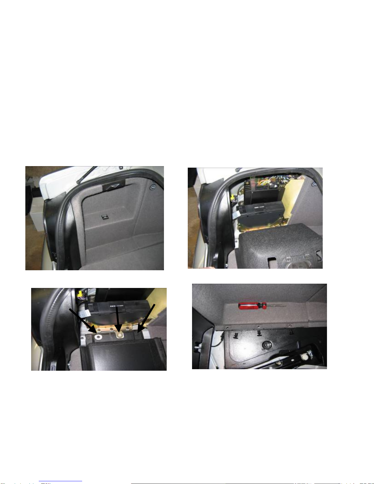
2. Remove the trunk liner and side door (driver’s side) compartment that covers the cd changer. (See Photos).
Take a flat head screw driver and carefully pry up on the lip of the fasteners to remove.
NOTE: Find a clean storage area in your garage, etc. to place the interior trim pieces, rear seat, etc. to protect
them from damage and dirt.
3. Unplug the wiring harness from the cd changer and remove the mounting screws (8mm) from bottom bracket
plate. Carefully lift the unit out ensuring no wires are still attached. Pay attention to the plugs and wires you
have removed, they will be used to connect the iceLink DA unit and wiring harness.
4. The DA Converter requires a 12v source. I tapped power off of the amp wiring harness. (see photo below)

The power wires for the DA Converter are positive + (Black / White Stripe) and Negative – (Solid Black) with a
plug on the other each that connects to the converter. NOTE The photo shows the positive wire as more blue
and white – This wire IS black and white. (I found this out the hard way… my + and – wires were not marked
from the factory and was forced to research for over two hours to confirm polarity $*%&#)
Below I have provided the exact steps to splicing your wires. If I was to do it over again, I would probably run
the positive wire to the battery while grounding the negative the same. Only steady hands should attempt this
spice…too deep with the Xacto Knife and …
Splicing Procedure – Take the Xacto Knife (Very sharp) and VERY CAREFULLY shave back the shroud
protecting the wire (white wire going to amp plug). PATIENCE GRASSHOPPER. Once the wire (white) is
exposed, take the positive wire (Black / White) from the DA Converter and wrap around the white wire very
tight (Better to solder – Just be careful ). Now wrap this connection good with electrical tape.
IMPORTANT –
1. CHECK TO MAKE CERTAIN THE
WIRE YOU ARE SPLICING IS 12v
POWER.
2. MAKE SURE YOUR HARNESS IS
THE SAME!
5. Run the Neg. wire (black) to ground. First, place a (U)
shaped connector on the negative wire and run it to the
closest threaded post on the back of the taillight housing
(driver’s side - U.S.). Unscrew the nut just enough to place
the wire underneath then CAREFULLY tighten the nut
back.
DO NOT OVERTIGHTEN YOU WILL CRACK THE
HOUSING!
6. Now get out the BMW Instructions that came with the
iceLink and match up the connectors from the cd changer to
the DA Converter. Pretty much plug-n-play here…

NOTE: Remove coax cable from amp (single pin cable left behind after changer removal and is still connected
to the amp … unplug it totally – Keep this cable stored with your changer in case you want to re-install…trust
me you won’t!
7. At this point you should have the DA Converter connected. Before we start running the harness to the front and
mount the cradle you need to make a DRY TEST RUN to see if the player works.
8. With the key out of the ignition re-connect the battery.
9. Now with everything lying in the trunk, carefully
remove the 15’ harness and carry it to the front driver’s
seat. BE CAREFUL not to snag the harness on anything
or undo the work you’ve just completed.
10. Place the iPod in the Dension cradle, insert key and turn
to the 2nd position.
11. Turn the head unit on. If the head unit is not set to the c
changer -- switch to it. NOTE: If the changer refuses to
come up and just displays TAPE temporarily -- STOP!
Turn the key to the off position and REMOVE the keys.
Go to the rear of the car and remove the 30A & 10A
fuses for the head unit and wait 5 minutes. Reconnect and try again.
d
12. Now you should see the player come to life. MAKE SURE YOU HAVE AT LEAST ONE PLAYLIST
SETUP. AFTER PLAYING AROUND UNPLUG THE 12v WIRE FROM THE CONVERTER.
13. Congratulations the easy part is done…GOOD JOB! Get some rest and rejuvenate the patience.
Look over the misc. photos below for reference on connections, etc. Now on to running the harness and trim/ panel
removal…

MISC. PHOTOS

Wiring Harness & Trim Panel Removal (Driver Side / Trunk)
Before we start running the harness and removing panels, STOP.
Take the time to wrap tape around the connector plugs that connect the harness, etc. to the DA Converter. Note in
the photos how I placed some electrical tape about 1” below the red / white RCA plugs. I did this to take some of
the pressure of the RCA plugs. It is not necessary to wrap tape around the RCA plugs. The point in wrapping
electrical tape around the connectors is to 1). Ensure they are properly seated and stay that way, 2). Protect the
wires, pins and connections in general and 3). It’s just good safe practice and provides a clean appearance.
Here we go…
1. Remove the drivers side panel in the same
manner you removed the access door to the
changer (Only one trim grommet is on the
side panel – (same grommet as the access
door under the phone badge symbol).
NOTE-The second grommet is DIFFERENT
and connects the rear panel to the side panel.
THESE TRIM GROMMETS UNSCREW!
Learn from me I broke two!
2. Unscrew the top / bottom left rear trim
grommet and carefully remove the side panel
exposing the insulation and factory wiring
harness’
3. Next remove the remaining rear trim
grommets EXCEPT THE LARGE CENTER ONE. (Keep everything together in your Zip Lock bags)
NOTE I had a hard time creating resistance to unscrew the grommets. If some break off it’s not the end of the
world.
4. Next remove the bottom section of the rear seat.
First, raise the center armrest all the way up. Go to the drivers side and grab
the bottom of the seat about 1/3 of the way towards the passenger side. Lift
up with some force until the seat unclips. Go to the other side and repeat.
Place in a clean location out of the way.
5. With the bottom section of the rear seat out, fold down the center arm rest and
locate the backside of the LARGE CENTER GROMMET. (You will have to
move the perforated insulation back a little… DO NOT BREAK OFF)
6. Squeeze the tabs and the grommet should pop off in the trunk.
7. Locate the grommet and remove the back panel. Go ahead and remove the
floor panel too. (If you remove the floor panel before removing the back
panel you may find yourself fishing the grommet out of the spare tire well. Sound like experience, huh?
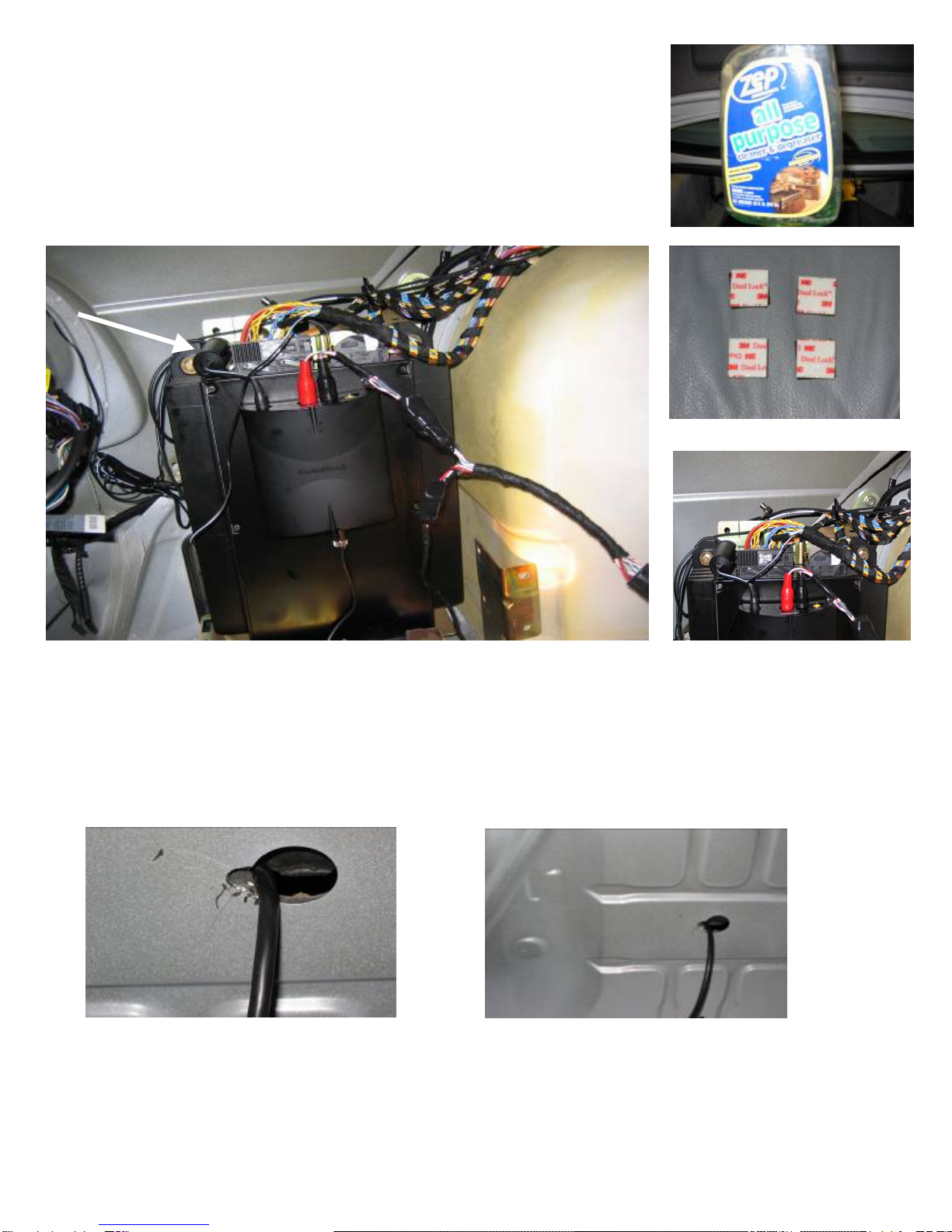
8. Now is a good time to mount the DA Converter to the Amp. First, clean the
Amp surface and back of converter with degreaser.
9. Evenly space four 3M Dual Lock fasteners to the back of the converter and
mount to the amp as shown. Heavy Duty Velcro may work too?
10. With the converter mounted to the amp, now clean up the wires around the amp. Note the position of the
converter and especially how the filter neatly fits next to the amp plug. IGNORE the wire hanging down… it
tucks neatly behind the amp.
11. While in the trunk, take your 11/32 drill bit and carefully drill a hole adjacent to the large grommet hole (SEE
PHOTOS). Take your time and do not push too hard – drill just enough to break through. Clean up the rest
with the grinder attachment (Dremel Tool) BE SURE TO SMOOTH ALL ROUGH EDGES.
12. Go ahead and run the wiring harness through your newly created hole. DO NOT DRESS THE HARNESS
WIRES…THIS IS DONE AT THE END OF INSTALLATION.

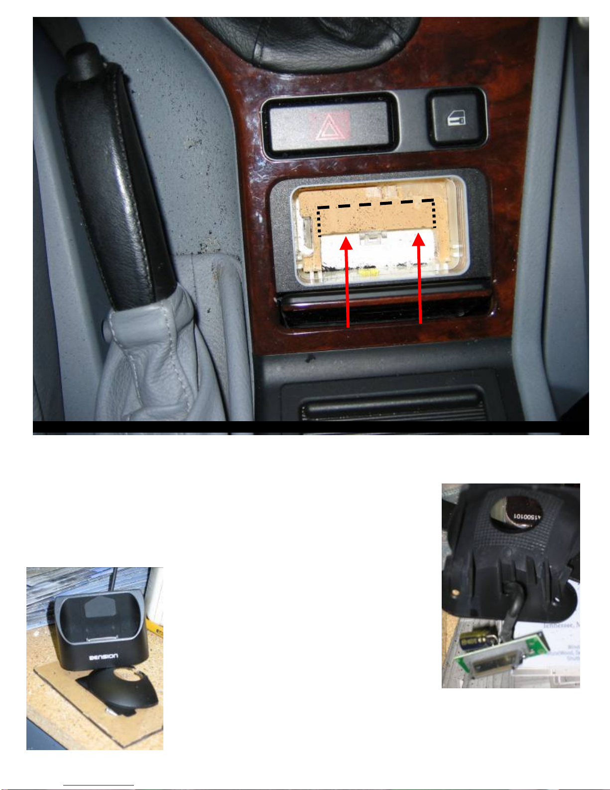
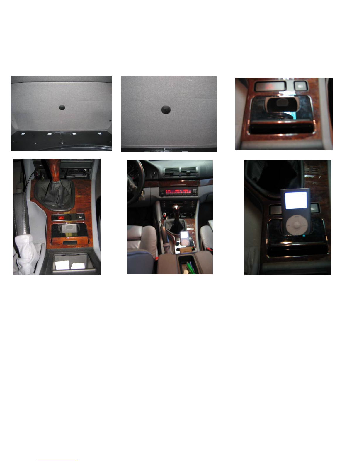
Dension Cradle & Ashtray Fabrication
To mount the cradle in the ashtray location requires some patience. If it’s late or you’re tired, save this next section
until you’re well rested – Cutting the required 1/16” lip off the ashtray lid takes steady hands, if not, new ashtray
lid. :~)
I chose to mount the iPod in the ashtray for a clean look and to have the ability to remove the iPod and close the
ashtray. Also, I wanted the iPod to lean towards the radio at a 45 degree angle. To accomplish this you have to
modify (cut) the cradle quite a bit. .
1. Remove the chrome ashtray liner. (Pull the ashtray lid all the way open…then take it a nudge farther. The
ashtray liner should pop up). UPDATE: Take the cradle apart NOW. (See detailed instructions below.)
2. Note the gear inside the ashtray. Take the cradle and set it in the ashtray with the edge of the cradle resting
against the gear. This is the angle I wanted. Also note how the metal support (springy) gets in the way. Let’s
get rid of it.
3. Take your side cutters and snip it out of the way…Carefully! Set the cradle back in the ashtray. Note how the
door will not close without grinding some of the cradle away. Let’s go…
4. Grind away about a 1/16” – 1/8” off the top of the cradle. Be sure to shape it the same. TAKE YOUR TIME
5. Once you have a good fit and closure you will realize you need some type of support below the cradle to have a
snug fit. Keep in mind you will be seating the iPod in the cradle and this requires a little force. Without
something supporting the cradle it will work loose over time…something you definitely DO NOT want to
happen.
6. To create the support piece (½” acrylic / plastic (clear)) we need to measure the enclosure carefully. I must
apologize here for not having the measurements to post… I lost them during clean up … I APOLOGIZE!
Anyway, it’s not too hard to make the
measurements…just make sure you note the little tabs
sticking out in the enclosure and especially the plastic
light housing sticking up (drivers side). Be careful not to
break the light housing, it’s what makes the cradle
installation look so professional at night.
SUPPORT SHOWN AS IT MOUNTS IN CAR.
TOP OF PHOTO = REAR OF CAR.
A
RROW DENOTES POINT TO PRY UP TO REMOVE.
7. Take your measurements and cut to rough size. Once
cut – Use the grinder to smooth the edges. I recommend
fitting a piece with a trial and error approach until snug.
Now place the cradle in the enclosure and mark for the
cut out. If you do not cut out for the cradle THE LID
WILL NOT CLOSE. MARK THE SUPPORT SO IT
FITS TIGHT AROUND THE CRADLE. Note the points
where the cradle touches the support, we will epoxy
these areas later.
REFERENCE PHOTOS BELOW.
To remove the support for shaping, take a small screw driver and carefully pry up.
(In front of the ashtray light housing – towards the rear seat)..
NOTE THE ARROWS – For the cradle to fit properly, grind this area more than the photo indicates.
8. (SEE UPDATE ABOVE FOR STEP 8)
To properly check the fit of the cradle in your new support – CAREFULLY
remove the very small screws located at the bottom of the cradle. BE
CAREFUL with the circuit board too. NOTE: THIS STEP SHOULD HAVE
BEEN DONE EARLIER BUT WAS LEFT HERE AS A “HOW TO”
9. Once apart, take the shell (the part with Dension imprinted) to the ashtray and
check for fit and closure.
10. For the ashtray to open and close properly –
(once the cradle is reassembled (later)) with
the plug -- you have to trim the edge
underneath the ashtray lid. The edge is about
a 1/16” and runs the width of the lid.
11. GO SLOWLY! To perform this procedure I
used a Dremel tool with a cut off attachment
and the console as a brace. Also, a good shop
light is a must!
12. Now test fit – the ashtray should close and the cradle
should hold itself in place pretty good. If not, locate the
areas where it touches and reshape (support), etc.
13. Next reassemble the cradle without the screws, foam and
circular mounting guide.
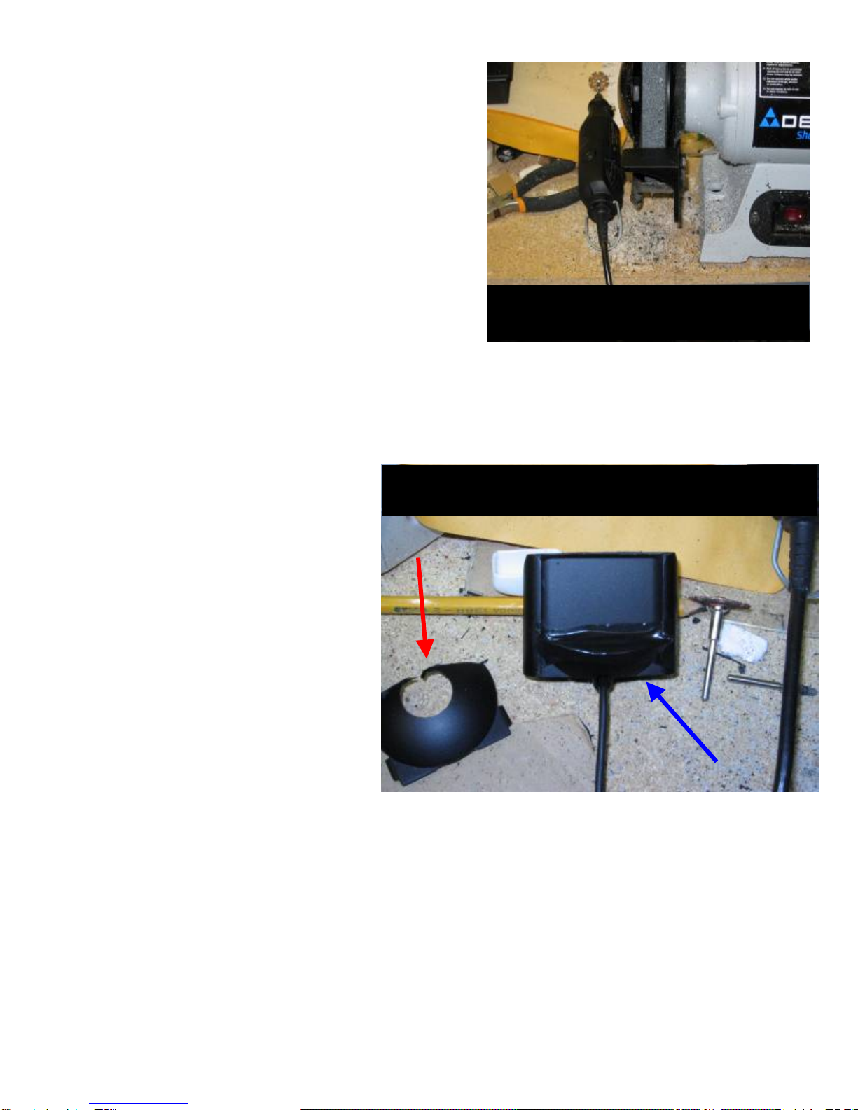
14. Note the large convexity of the back after reassembling.
There is no way this is going into the ashtray enclosure the
way it is…Time to cut … FUN FUN!
Dremel w/ cut-off Attachment
Grinder -- (The width of the grinder wheel is almost
perfect for grinding the shape of the light housing.)
15. Carefully mark and cut most of the backing away. (SEE
PHOTOS BELOW)
BACKSIDE OF DENSION ICELINK CRADLE
RED ARROW – NOTE HOW MUCH IS CUT OFF OF BACKING
BLUE ARROW – ELECTRICAL TAPE COVERING OPENING
16. Once cut and reassembled be sure to cover the hole exposing part of the electronics with electrical tape. (A
really nice move here would be to fabricate a half moon cover and epoxy to seal. Especially if a drink was to
spill. However, I ran out of time and I feel properly covering the opeining with electrical tape provides some
level of protection.)
17. Now test fit. Be sure everything fits
perfectly … No turning back once epoxy
sets! If everything looks good…GREAT
JOB! DON’T EPOXY YET!
18. Now we have to get the wire from the
bottom of the ashtray thru the center
console to the center of the back seat.
WHOA! One step at a time…
19. Still confident everything fits perfectly so
far RIGHT? Make sure before
proceeding!
20. Ok, now you should remove the top of the
center console. This job is not that hard
and you only need to raise it off the base
about three inches – NOT totally off.
For detailed steps on how to remove the center console please go to BMWTIPS.COM – Tips & Tricks / Interior
/ Center Console Removal / e39.

21. With the center console raised about
three inches – Drill a hole in the b
of the enclosure right beneath where
the cord comes out of the cradle. Your
hole should be centered and toward
the rear seat but still on the bottom n
the side of the enclosure. RAISING
THE CONSOLE WHILE DRILLING
ENSURES YOU DON’T DAMAGE
ANY WIRES/ AIR DUCT, ETC.
NOTE – Photo shows the hole a little smaller than it actually needs to be.
ottom
sot
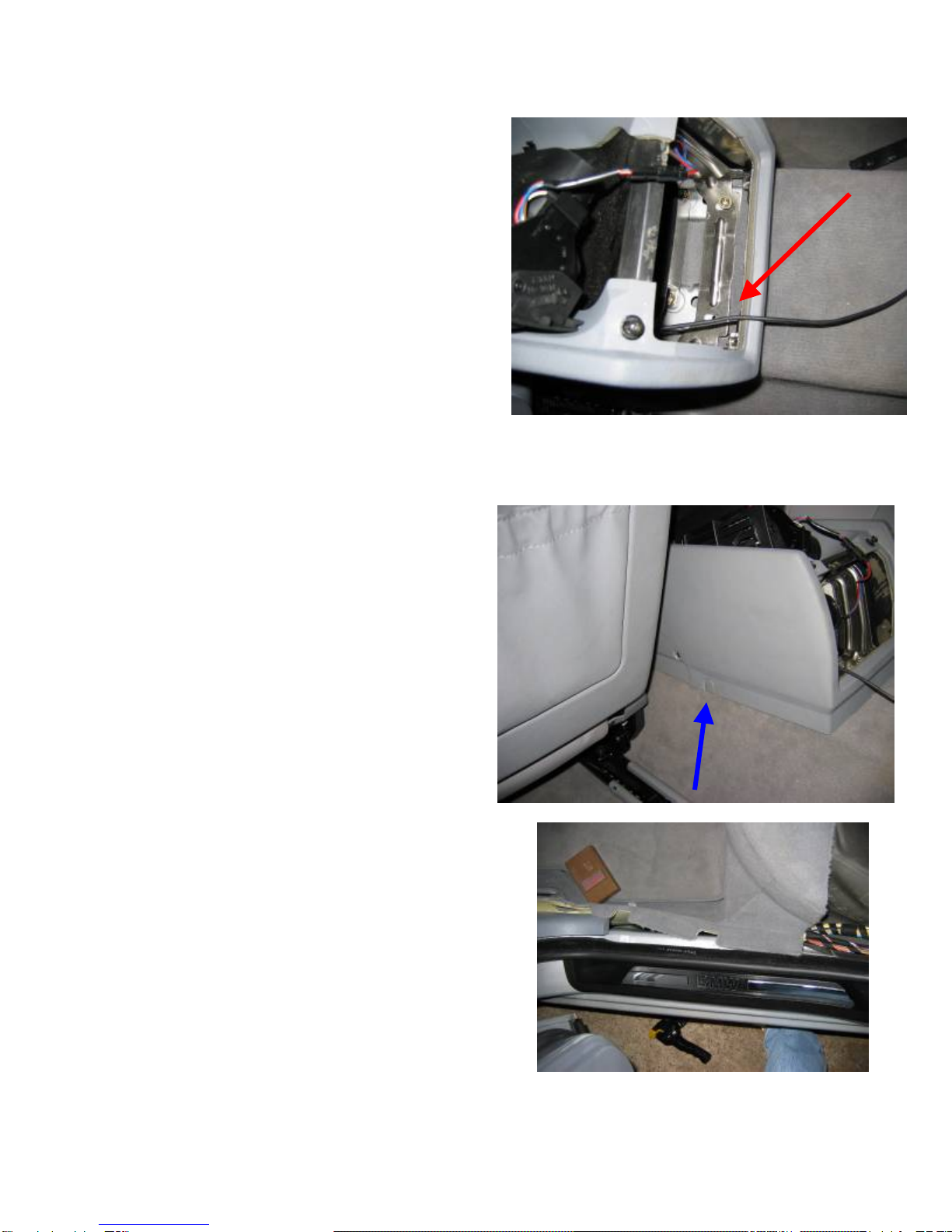
22. Make the hole large enough for the l g
23. Once you have the connector and some wire through the hole in the ashtray enclosure try grabbing and gently
connector to come through. You wil
have to raise the console while pushin
the connector through. TAKE YOUR TIME this part can be a little frustrating.
pulling it through the access hole for the phone wiring harness (SEE PHOTO BELOW – BLUE ARROW).
Once you have it to this point STOP and remove the rear ac vents if not already done. (See BMWTIPS.COM
for vent removal help)
With the console up 3 inches (RED ARROW) you should have no problems grabbing the connector
and (SLOWLY) pulling the remaining wire through this hole (BLUE ARROW).
24. With the excess wired pulled, now route it down the
25. ust cut a hole in the carpet here (SEE RED
t
26. the cable you
he
7. Next remove the plastic threshold (NOT THE BMW
g
28. Unhook the carpet from the rear seat clips. Also, le
t
9. Ok ENOUGH TALK…run that wire! O TIGHT!
e).
30. Congratulations you’re almost home!
31. With the wire run now we can hook up the connectors and
drivers side of the console, adjacent to the air duct, to
the back of the console (Back to the rear ac vent
opening).
Now we m
ARROW IN PHOTO) and run the cable ONLY 18” to
make the connection. YEAH! At this point I strongly
recommend a second person to help hold the carpet
back while the other fishes the wire through. I did no
have a person to help out and it cost me AT LEAST an
hour and a half of extra labor time.
To pull the carpet back enough to run
must first remove the side kick panels at each rear
passenger door. Take a 10mm socket and remove t
screw holding the kick panels and top of the rear seat. T
door opening about a foot off the sill. (SEE PHOTO – RED ARROW)
he screws are located at the bottom rear portion of the
2SILL PLATE). Just pull up with some force, they
just snap in and out. I broke a couple of mine durin
the process. Hopefully there not too expensive or
hard to replace?
now is a good time to unscrew the rear base conso
screw (driver’s side only). (SEE PHOTO – BLUE
ARROW) This will help out a lot when snaking tha
$%#($ wire.
2IMPORTANT -- DO NOT PULL IT TO
Take it down the top left side of the center hump.
NOT ON TOP – Just off the top edge (driver’s sid
mount it to the center of the rear seat. NOTE: You do not
have a lot of extra slack coming from the cradle. I suggest
mounting the connector and wires the way I have them
shown 1.) To ensure no stress is put on the connectors /
wires and 2.) To protect them if the center seat is
occupied. (See Photo Below)
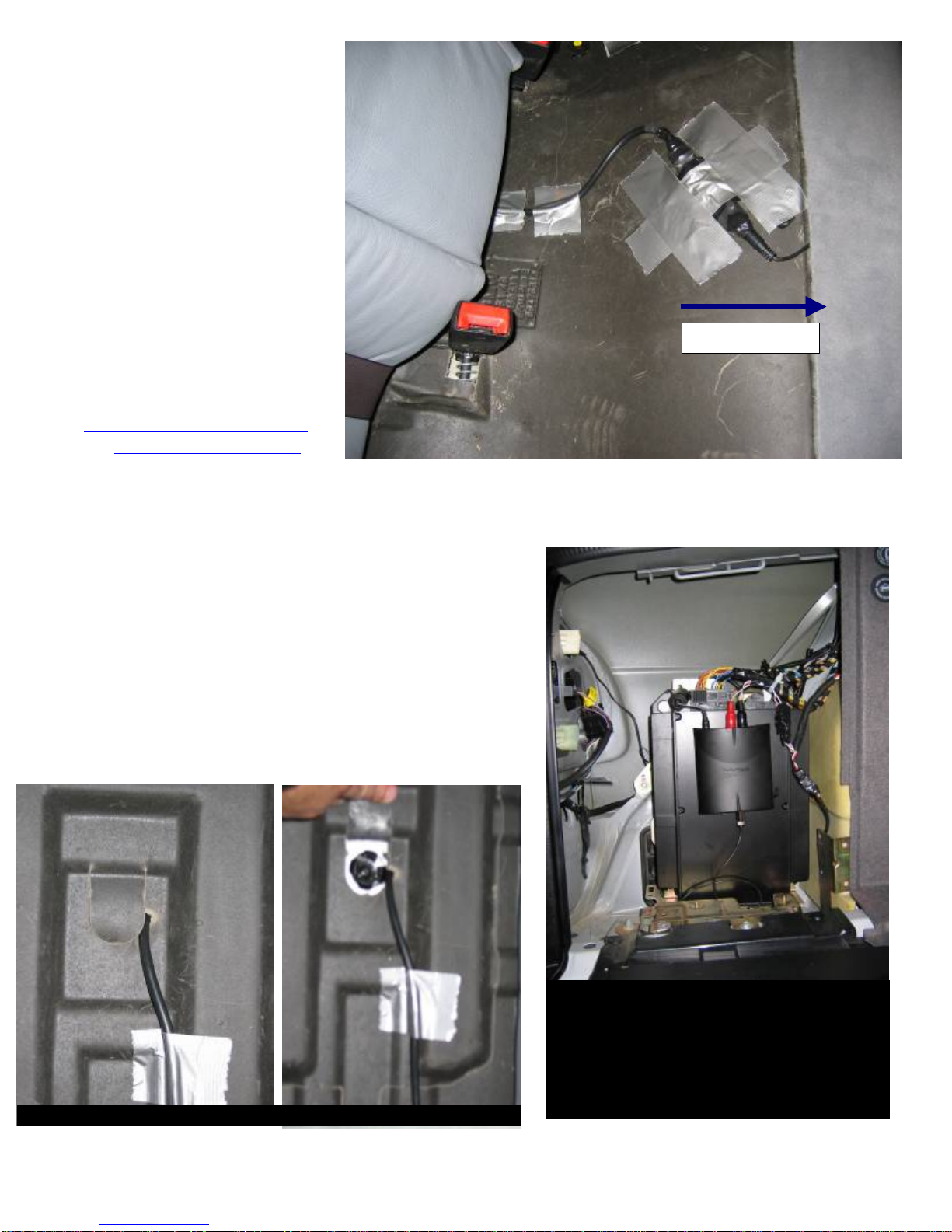
Front of Car
32. With everything now taped and
os).
3. Test to make sure everything
34. CONGRATULATIONS
BE SURE TO VISIT:
.COM
secure, go to the trunk and route
the wires with the factory
wiring harnesses. (See phot
3works.
YOU’RE DONE!
WWW.DENSIONUSA
OR
WWW.DENSION.COM
FOR FIRMWARE UPDATES
.
PDATE BER 26TH, 2005 SION
3 TAGS ARE NOT HE FIRST
U
AS OF DECEM
THE LATEST FIRMWARE VER
IS 2.03 UPDATE YOUR IPOD.
ID
SUPPORTED UNTIL T
PART OF 2005.
This picture shows the DA Converter mounted
to the amp. NOTE: The converter is mounted
too high in this picture.
I had to re-mount the converter lower so the
panel cover would close. The CD changer
MAY fit too once the converter is lowered.
Rear Trunk / Seat Access Panel With Wire Routing
Miscellaneous Photos
Other manuals for ice-Link: Plus
2
Other Dension Automobile Accessories manuals

Dension
Dension IPH-9201-5 User manual

Dension
Dension IPH1CR0 User manual

Dension
Dension Smartlink MHL-9202-1 User manual

Dension
Dension ice>Link Gateway 500 User manual

Dension
Dension Gateway Pro BT User manual

Dension
Dension Gateway Five User manual

Dension
Dension WiRC User manual

Dension
Dension ICE>LINK LITE User manual

Dension
Dension Gateway Five User manual

Dension
Dension 500S User manual


