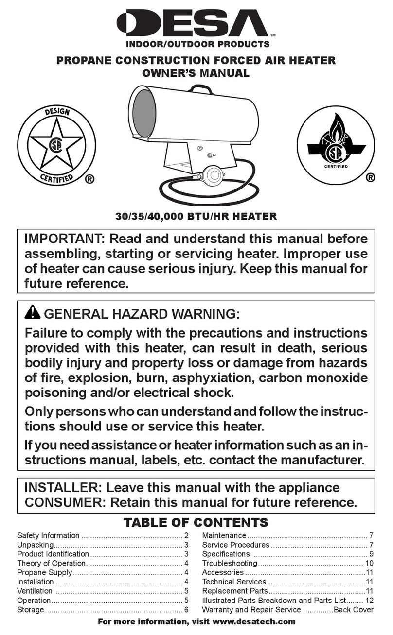
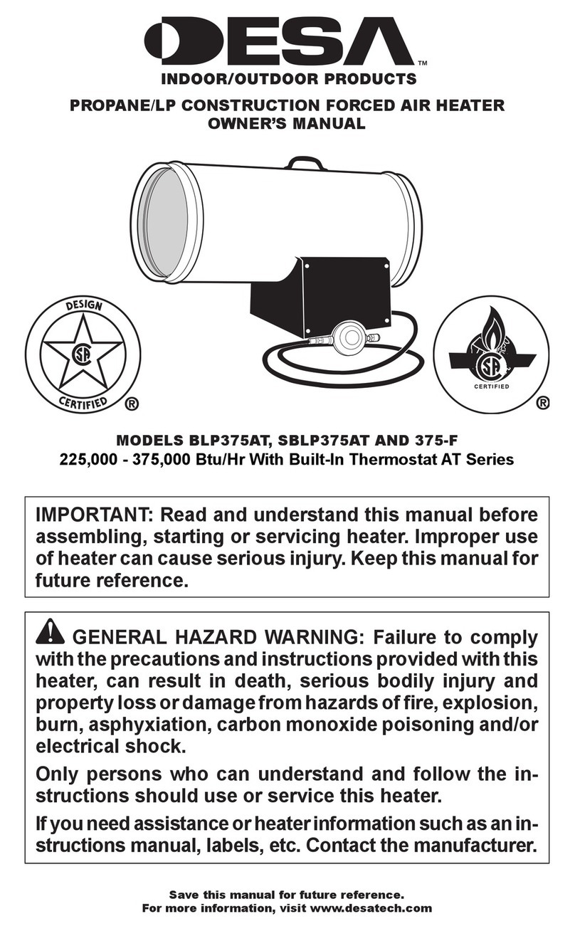
Desa 80-CC User manual

VARIABLE 40-80,000 BTU/HR
75-200,000 BTU/HR
PROPANE CONSTRUCTION CONVECTION HEATER
OWNER’S MANUAL
IMPORTANT: Read and understand this manual before
assembling, starting or servicing heater. Improper use
of heater can cause serious injury. Keep this manual for
future reference.
GENERAL HAZARD WARNING:
Failure to comply with the precautions and instructions
provided with this heater, can result in death, serious
bodily injury and property loss or damage from hazards
of re, explosion, burn, asphyxiation, carbon monoxide
poisoning and/or electrical shock.
Only persons who can understand and follow the instruc-
tions should use or service this heater.
If you need assistance or heater information such as an in-
structions manual, labels, etc. contact the manufacturer.
Save this manual for future reference.
For more information, visit www.desatech.com
200,000
BTU/HR
TABLE OF CONTENTS
Safety Information ............................................... 2
Unpacking............................................................ 3
Theory of Operation............................................. 3
Product Identication........................................... 3
Ventilation ........................................................... 3
Propane Supply................................................... 4
Installation ........................................................... 4
Operation............................................................. 5
Storage................................................................ 7
Maintenance........................................................ 7
Troubleshooting................................................... 8
Specications ...................................................... 9
Replacement Parts.............................................. 9
Technical Services............................................... 9
Accessories ......................................................... 9
Illustrated Parts Breakdown and Parts List........ 10
Warranty and Repair Service ............................ 14

www.desatech.com 116557-01C2
SAFETY INFORMATION
WARNING: This product
contains and/or generates
chemicals known to the State
of California to cause cancer or
birth defects or other reproduc-
tive harm.
WARNING: Fire, burn inha-
lation and explosion hazard.
Keep solid combustibles, such
as building materials, paper or
cardboard,asafedistance away
fromtheheaterasrecommended
by the instructions. Never use
the heater in spaces which do or
may contain volatile or airborne
combustibles or products such
asgasoline,solvents, paintthin-
ner, dust particles or unknown
chemicals.
WARNING: Not for home or
recreational vehicle use.
The heater is designed for use as a construction
heater in accordance with ANSI Z83.7•CGA
2.14. Other standards govern the use of fuel
gases and heating products for specific uses.
Your local authority can advise you about these.
The primary purpose of construction heaters is
to provide temporary heating of buildings under
construction, alteration or repair. Properly used,
the heater provides safe economical heating.
Products of combustion are vented into the area
being heated.
We cannot foresee every use which may be made
of our heaters. CHECK WITH YOUR LOCAL
FIRE SAFETY AUTHORITY IF YOU HAVE
QUESTIONS ABOUT HEATER USE.
Other standards govern the use of fuel gases and
heat producing products for specic uses. Your
local authorities can advise you about these.
Carbon Monoxide Poisoning: Some people are
more affected by carbon monoxide than others.
Early signs of carbon monoxide poisoning re-
semble the flu, with headaches, dizziness and/or
nausea. If you have these signs, the heater may not
be working properly. Get fresh air at once! Check
for proper ventilation and have heater serviced.
Propane Gas: Propane gas is odorless. An odor-
making agent is added to propane gas. The odor
helps you detect a propane gas leak. However, the
odor added to propane gas may fade. Propane gas
may be present even though no odor exists.
Make certain you read and understand all warn-
ings. Keep this manual for reference. It is your
guide to safe and proper operation of this heater.
1. Install and use heater with care. Follow all
local ordinances and codes. In the absence of
local ordinances and codes, refer to the Stan-
dard for Storage and Handling of Liqueed
Petroleum Gas, ANSI/NFPA 58 Natural Gas
Installation Code, CAN/CGA B149.2. This
instructs on the safe storage and handling of
propane gases.
2. This product has been approved for use in the
Commonwealth of Massachusetts.
3. Use only propane gas set up for vapor with-
drawal.
4.
Provide adequate ventilation. Before using
heater, provide at least a 2.5 square foot
(0.232 m2) (80,000 btu heaters) or 6.0 square
foot (0.557 m2) (200,000 btu heaters) opening
of fresh, outside air.
5. For indoor use only. Do not use heater out-
doors.
6. Keep heater away from strong drafts, wind,
water spray, rain or dripping water.
7. Do not use heater in occupied dwellings or in
living or sleeping quarters.
8. Do not use heater in a basement or below
ground level. Propane gas is heavier than air.
If a leak occurs, propane gas may sink to the
lowest possible level.
9. Keep appliance area clear and free from com-
bustible materials, gasoline, paint thinner and
other flammable vapors and liquids. Dust is
combustible. Do not use heater in areas with
high dust content.
10. Minimum heater clearances from combustibles:
80,000 Btu heaters
Sides: 3 feet (91 cm); Top: 6 feet (1.83 m)
100-200,000 Btu heaters
Sides: 3 feet (91 cm); Top: 7 feet (2.1 m)
11. Keep heater at least six feet (1.83 m) from
propane tank(s).
12. Keep propane tank(s) below 100° F (37.8° C).
13. Use only the hose and factory preset regulator
provided with the heater.
14. Check heater for damage before each use. Do
not use a damaged heater.

www.desatech.com
116557-01C 3
200,000
BTU/HR
SAFETY INFORMATION
Continued
Outer
Shell
Ignitor
Button
Ball Valve
Control Knob
Button
Figure 1 - 200,000 Btu Model Shown
15. Check hose before each use of heater. If highly
worn or cut, replace with hose specied by
manufacturer before using heater.
16. Do not alter heater. Keep heater in its original
state.
17. Do not use heater if altered.
18. Locate heater on stable and level surface if
heater is hot or operating.
19. Not intended for use on nished floors.
20. Never block air inlet (bottom of shell) or air
outlet (around top of shell) of heater.
21. Do not leave heater unattended.
22. Keep children and animals away from
heater.
23. Always run heater with control knob at LO,
MED or HI settings. Never set control knob
between OFF, LO, MED or HI settings. Flash-
back may occur.
24. Never move, handle or service a hot or operat-
ing heater. Severe burns may result. You must
wait 15 minutes after turning heater off.
25. To prevent injury, wear gloves when handling
heater.
26. Never attach duct work to heater.
27. Turn off propane supply to heater when not
in use.
28. Use only original replacement parts. This
heater must use design-specific parts. Do
not substitute or use generic parts. Improper
replacement parts could cause serious or fatal
injuries.
UNPACKING
1. Remove all packing items applied to heater for
shipment. Keep plastic cover caps (attached to
inlet connector and hose/regulator assembly)
for storage.
2. Remove all items from carton.
3. Check all items for shipping damage. If heater
is damaged, promptly inform dealer where you
bought heater.
THEORY OF OPERATION
The Fuel System: The hose/regulator assembly
attaches to the propane gas supply. This provides
fuel to the heater.
The Ignition System: The piezo ignitor lights
the pilot.
The Automatic Control System: This system causes
the heater to shut down if the flame goes out.
PRODUCT
IDENTIFICATION
VENTILATION
WARNING: Provide at least
a 2.5 square foot (0.23 m2)
opening of fresh, outside air
while running heater. If proper
fresh, outside air ventilation is
not provided, carbon monoxide
poisoning can occur. Provide
proper fresh, outside air ventila-
tion before running heater.
Valve
Inlet
Safety Pilot Valve

www.desatech.com 116557-01C4
200,000
BTU/HR
1. Care must be taken to protect hands during this
step. Lift outer shell straight up as shown in Fig-
ure 2, until all three clips engage slots in lower
shell. Screw holes will line up at this point.
2. Lock clips into place with 3 screws as shown
in Figure 2. The heater must not be operated
unless the outer shell is properly extended and
fully locked into place.
Figure 2 - Lifting Outer Shell
(200,000 Btu Model Shown)
3 Screws
per Clip
Outer
Shell
Clip in Slot
of Lower
Shell
PROPANE SUPPLY
You must provide propane gas and propane tank(s).
Use this heater only with a propane vapor
withdrawal supply system. See Chapter 5 of the
Standard for Storage and Handling of Liqueed
Petroleum Gas, ANSI/NFPA 58 and/or CAN/CGA
B149.2. Your local library or re department will
have this booklet.
This heater will operate with a 20 pound (9.07 kg)
propane tank. However, you can only operate it in
the LOW position during mildly cool weather for
a very short time.At higher heat settings or during
colder weather, you must use larger tanks.
The amount of propane gas ready for use from pro-
pane tanks varies. Two factors decide this amount.
1. The amount of propane gas in tank(s)
2. The temperature of tank(s)
The chart below shows the minimum number of
100 pound (45 kg) tanks needed to run the heater.
Connect tanks together with a manifold.
Average Temperature Number
At Tank Location Of Tanks
(80,000 Btu models)
20° F (-6.7° C) to 60° F (15.6° C) 1
0° F (-17.8° C) to 20° F (-6.7° C) 2
(200,000 Btu models)
20° F (-6.7° C) to 60° F (15.6° C) 2
0° F (-17.8° C) to 20° F (-6.7° C) 3
Less gas is vaporized at lower temperatures. Your
local propane gas dealer will help you select the
proper supply system.
INSTALLATION
WARNING: Review and un-
derstand the warnings in the
Safety Information section, page
2. They are needed to safely op-
erate this heater. Follow all local
codes when using this heater.
CAUTION: Never ignite and/
or run this heater unless the
shells are fully extended and
locked into position.
OUTER SHELL
IMPORTANT: When the heater is rst removed
from carton, the outer shell is in the down posi-
tion. Protect hands before lifting outer shell. Never
grasp bare metal without hand protection.
CONNECTING TO GAS SUPPLY
WARNING:Testallgaspiping
and connections for leaks after
installation or servicing. Never
use an open ame to check for
a leak. Apply a mixture of liquid
soap and water to all joints.
Bubbles forming show a leak.
Correct all leaks at once.
1. Provide propane supply system (see Propane
Supply).
2. Connect fuel gas tting on hose/regulator
assembly to propane tank(s). Turn fuel
gas tting counterclockwise into threads
on tank. Tighten rmly using a wrench.
IMPORTANT: Tighten regulator with vent
pointing down. Pointing vent down protects
regulator from weather damage.
3. Connect hose to the valve inlet. Tighten rmly
using a wrench. You must use the regulator sup-
plied with heater even if propane tank has one.

www.desatech.com
116557-01C 5
Off/
Apagado/
Arrêt
Lo/Bajo/
Bas
Med/
Medio/
Moyen
Hi/Alto/
Haut
Figure 3 - Regulator Position
Propane
Tank
Propane Supply
Valve
Regulator
Hose
POL
Fitting
INSTALLATION
Continued
Figure 4 - Hose and Valve Inlet
(200,000 Btu Model Shown)
Hose Valve Inlet
OPERATION
WARNING: Review and un-
derstand the warnings in the
Safety Information section, page
2. They are needed to safely op-
erate this heater. Follow all local
codes when using this heater.
80,000 BTU HEATER
TO START HEATER
1. Follow all installation, ventilation and safety
information.
2. Locate heater on stable and level surface. Make
sure strong drafts do not blow on heater.
3. Make sure unit is turned off by slightly
depressing and turning control knob fully
clockwise to OFF.
4. Open propane supply valve on propane tank(s)
slowly. Note: If not opened slowly, excess-
flow check valve on propane tank may stop
gas flow. If this happens, you may hear a click
inside the regulator assembly, this is the check
valve closing. To reset the excess flow check
valve, close propane supply valve and open
again slowly.
5. Slightly depress and turn control knob counter-
clockwise to the LO position (see Figure 5).
6. With the control knob pushed all the way in,
press and release the piezo ignitor button.
Keep pressing piezo ignitor button until the
burner lights. Hold control knob down for a
maximum of 15 seconds while attempting ig-
nition. If heater does not ignite, release control
knob and wait 3 minutes before attempting to
reignite.
7. After ignition, hold control knob down for
about 30 seconds.This activates the automatic
control system.
4. Open propane supply valve on propane tank(s)
slowly. Note: If not opened slowly, excess-
flow check valve on propane tank may stop
gas flow. If this happens, you may hear a click
inside the regulator assembly, this is the check
valve closing. To reset the excess flow check
valve, close propane supply valve and open
again slowly.
5. Check all connections for leaks. Apply mix-
ture of liquid soap and water to gas joints.
Bubbles forming show a leak that must be
corrected.
Figure 5 - Control Knob and Piezo Ignitor
Piezo Ignitor Button
Control Knob

www.desatech.com 116557-01C6
8. Whenburnerremains lit,set heateratthe desired
heatlevelbyslightly depressingthecontrolknob
and turning it counterclockwise to the MED or
HI settings (see Figure 5, page 5).
9. If burner goes out, turn off gas. Slightly depress
and turn control knob fully clockwise to OFF.
Check fuel supply. If adequate fuel is available,
restart heater beginning at step 1, page 5.
CAUTION:Always runheater
with control knob at LO, MED or
HI settings. Never set control
knob between OFF, LO, MED or
HI settings as ashback may
occur.
FLAME PATTERNS
Figure 6 shows a correct flame pattern. The burner
flame is mostly blue with a slight yellow coloring
on the ends.
Figure 7 shows an incorrect flame pattern. The
flame is mostly yellow. The incorrect flame pattern
results from low gas pressure or from flashback.
OPERATION
Continued
CAUTION: Running heater
between settings may cause
ashback. During ashback, the
burner ame is mostly yellow.
The ame will burn inside the
burner tube, causing a roaring
noise. If ashback occurs, turn
heater off. After burner tube
cools, restart the heater.
TO STOP HEATER
1. Tightly close propane supply valve on propane
tank(s). Allow heater to burn remaining fuel
in hose.
2. Shut off burner. Do this by pushing in the
control knob and turning clockwise to the OFF
position.
TO RESTART HEATER
1. Wait ve minutes after stopping heater.
2. Restart heater by following To Start Heater,
page 5.
WARNING: Review and un-
derstand the warnings in the
Safety Information section, page
2. They are needed to safely op-
erate this heater. Follow all local
codes when using this heater.
Slight Yellow
Coloring on
Flame Ends
Burner
Tube
Blue
Flame
Figure 6 - Correct Flame Pattern at High
Position
Yellow
Flame
Flame Inside
Burner Tube
(makes
roaring
noise)
Blue
Flame
Figure 7 - Incorrect Flame Pattern During
Flashback

www.desatech.com
116557-01C 7
OPERATION
Continued
200,000 BTU/HR HEATER
TO START HEATER
1. Before lighting pilot fully close the ball valve
(turn knob fully clockwise).
2. Fully openthevalve onthe propanecylinderand
wait 15 seconds before proceeding to step 3.
3. Depress red button on safety pilot valve admit-
ting gas to the heater. Then push and release
the ignitor button until the pilot lights.
4. When the pilot lights, continue to hold the but-
ton depressed for 30 seconds, then release.
5. If pilot goes out, wait 5 minutes and repeat the
lighting procedure.
6. When the pilot remains lit, open the ball valve
(turn knob counterclockwise) to light main
burner. Partially close valve to regulate heat
output.
STORAGE
CAUTION:Disconnectheater
from propane supply tank(s).
CAUTION: Be careful not to
locate ngers in groves on side
of heater, in vent holes or on
bottom of shell when collaps-
ing shell to the down position.
Severe cuts may occur. Always
wear hand protection when
grasping bare metal.
1. The heater should be inspected before each use
and at least annually by a qualied person.
2. Before each use, check the soft "O" ring seat at
the bullnose of the POL tting. If the "O" ring
is cut, scuffed or otherwise damaged, replace
the POL tting with part number LPA4020.
3. Turn off the gas at the propane/LP gas supply
cylinder(s) when the heater is not in use.
4. Heater is to be stored indoors. The connection
between propane/LP gas supply cylinder(s)
and heater must be disconnected, cylinder(s)
removed from the heater and stored outdoors
in accordance with Chapter 5 of the Standard
for Storage and Handling of Liqueed Petro-
leum Gases ANSI/NFPA 58 and CSA B149.1,
Natural Gas and Propane Installation Code.
5. Store in a dry, clean and safe place.
MAINTENANCE
WARNING: Never attempt
to service heater while it is
connected to propane supply,
operating or hot. Severe burns
can occur.
1. Keep heater clean.
2. Inspect heater before each use. Check connec-
tions for leaks. Apply mixture of liquid soap
and water to connections. Bubbles forming
show a leak that must be corrected. Correct
all leaks at once.
3. Inspect hose/regulator assembly before each
use. If hose is highly worn or cut, replace.
4. Have heater inspected yearly by a qualied
service person.
Figure 8 - Starting Heater
Ignitor
Button
Ball Valve Control
Knob Button
TO STOP HEATER
1. Securely close valve on the propane cylinder.
2. Continue to operate heater until all fuel in the
hose has burned.
3. Fully close the ball valve.
TO RESTART HEATER
1. Securely close valve at propane cylinder.
2. Wait 5 minutes.
3. Restart heater by following To Start Heater,
page 6.
Safety Pilot
Valve

www.desatech.com 116557-01C8
TROUBLESHOOTING
WARNING: Never service heater while it is plugged in, connected
to propane supply, operating or hot. Severe burns and electrical
shock can occur.
REMEDY
1. Open propane supply valve
slowly
2. Close propane supply valve
on propane tank and reopen
slowly
3. Replace burner orice
4. Check to assure ignitor elec-
trode gap is .195" Check wire
lead for damage. Replace
piezo ignitor and/or ignitor
electrode as necessary
5.
Clean or replace pilot assembly
1. Relight, hold automatic control
valve button in 45 seconds
2. Check propane tank(s) for
proper gas supply
3. Tighten connection or replace
thermocouple
4. Replace automatic control
valve
1. Turn valve counter clockwise
to HIGH
2. Replace gas orice
3. Check gas supply; check
regulator output
4. Consult propane gas supplier
OBSERVED FAULT
Burner fails to light
Pilot lights but goes out when
automatic control valve button
is released (200,000 Btu models
only)
Burn rate is low
POSSIBLE CAUSE
1. Propane supply valve closed
on propane tank(s)
2. Excess flow check valve
closed
3. Blockage in burner orice
4. Piezo ignition system not
sparking
5. Pilot orice clogged
(200,000 Btu models only)
1. Not enough warm up time
2. Low gas pressure
3. Thermocouple loose or needs
to be replaced
4. Automatic control valve needs
to be replaced
1. Control valve is on LOW
2. Plugged gas orice
3. Low gas pressure
4. Low fuel supply

www.desatech.com
116557-01C 9
REPLACEMENT PARTS
WARNING: Use only original
replacement parts. This heater
must use design-specic parts.
Do not substitute or use generic
parts. Improper replacement
parts could cause serious or fa-
tal injuries. This will also protect
your warrantycoverageforparts
replaced under warranty.
PARTS UNDER WARRANTY
Contact authorized dealers of this product. If they
can’t supply original replacement part(s), either
contact your nearest Parts Central or call DESA
Heating Products’ Technical Service Department
at 1-866-672-6040.
When calling DESA Heating Products, have ready
• your name
• your address
• model number of your heater
• how heater was malfunctioning
• purchase date
PARTS NOT UNDER WARRANTY
Contact authorized dealers of this product. If
they can’t supply original replacement part(s),
either contact your nearest Parts Central (listed in
Authorized Service Center booklet) or call DESA
Heating Products at 1-866-672-6040 for referral
information.
When calling DESA Heating Products, have ready
• model number of your heater
• the replacement part number
SPECIFICATIONS
TECHNICAL SERVICES
You may have further questions about this heater.
If so, contact DESA Heating Products’ Technical
Service Department at 1-866-672-6040. When
calling, please have your model and serial numbers
of your heater ready.
You can also visit DESAHeating Products’Techni-
cal Service web site at www.desatech.com.
ACCESSORIES
Purchase heater accessories and parts from your
nearest dealer or service center. If they can not
supply an accessory or part, either contact your
nearest Parts Central (listed in the separate Au-
thorized Service Center booklet) or call DESA
Heating Products’ at 1-866-672-6040. You can
also write to the address listed on the back page
of this manual.
80,000 BTU
•
Rating: 40,000 - 80,000 Btu/hr (11.72 - 23.4 kW)
• Type of Gas - Propane/LP Only
• Gas Supply Pressure to regulator: Maximum -
Bottle Pressure, Minimum - 5 psig (34.5 kPa)
• Gas Supply Pressure regulator out:
25" W.C. (63.5 cm)
• Ignition: Piezo Ignitor
•
Minimum Ambient Temp. Rating: 0° F (-17.8° C)
• Fuel Consumption/hr: 1.85 - 3.71 lb
(0.83 – 1.68 kg)
• Fuel Orice Port No.: 1
• Fuel Orice Port Size: 0.086" (2.18 mm)
200,000 BTU
•
Rating: 75,000 - 200,000 Btu/hr (22.0 - 58.6 kW)
• Type of Gas: Propane/LP Only
• Gas Supply Pressure to regulator: Maximum -
Bottle Pressure, Minimum - 15 psig (103 kPa)
• Gas Supply Pressure regulator out:
10 psig (68.9 kPa)
• Ignition: Piezo Ignitor
•
Minimum Ambient Temp. Rating: 0° F (-17.8° C)
• Fuel Consumption/hr: 3.48 - 9.28 lb
(1.58 - 4.21 kg)
• Fuel Orice Port No.: 6
• Fuel Orice Port Size: 0.0320" (0.813 mm)

www.desatech.com 116557-01C10
ILLUSTRATED PARTS BREAKDOWN
MODELS
80-CC, RCP80VC, SPC-80CC, TC106 AND TC80VC
1
2
3
4
10
22
21
6
8
7
13
12
16
9
23
14
15 18
17
19
20
5
11

www.desatech.com
116557-01C 11
PARTS LIST
MODELS
80-CC, RCP80VC, SPC-80CC, TC106 AND TC80VC
This list contains replaceable parts used in your heater. When ordering parts, follow the instructions
listed under Replacement Parts on page 9 of this manual.
KEY
NO. PART NO. DESCRIPTION QTY.
1 113785-01 Cap 1
2 113781-01 Upper Shell 1
3 113825-01 Lower Shell 1
4 113778-01 Ring Shield 1
5 ** Base 1
6 116617-01 Ignitor Electrode 1
7 103854-01 Thermocouple Bracket 1
8 113790-01 Thermocouple 1
9 100898-01 Thin Hex Nut 2
10 102445-01 Piezo Ignitor Kit 1
11 098508-01 Valve Retainer Nut 1
12 099393-03 Control Knob 1
13 117166-01 Nozzle Locator 1
14 116556-01 Nozzle 1
15 116570-01 Fuel Tube Kit 1
16 103929-01 Burner Tube Kit 1
17 099460-01 Brass Hex Cap 1
18 116554-01 Automatic Valve 1
19 117059-01 Adapter, 1/4 FPT x 1/4 MPT 1
20 113795-01 Female Elbow Fitting, 1/4 FPT x 3/8 FLR 1
21 115626-01 Hose/Regulator Assembly, 10 foot 1
22 117060-01 Tube Fitting 1
23 099230-02 Shoulder Screw 1
PARTS AVAILABLE - NOT SHOWN
117069-02 80,000 Btu Rating Decal 1
113808-07 Hang Tag (English) 1
113808-08 Hang Tag (Spanish) 1
113808-09 Hang Tag (French) 1
113805-04 Installation Decal (English) 1
113805-05 Installation Decal (Spanish) 1
113805-06 Installation Decal (French) 1
113802-17 Model Decal 1
116558-01 Control Position Decal 1
**Not a eld replaceable part

www.desatech.com 116557-01C12
3
10
24
23
8
4
13
15
5
19
14
22
20
16
17
25
1
26
2
21
11
9
27
29
6
23
12
7
18
ILLUSTRATED PARTS BREAKDOWN
MODELS
200C, RCP200V(A), SPC-200C, TC107 AND TC200V(A)

www.desatech.com
116557-01C 13
PARTS LIST
MODELS
200C, RCP200V(A), SPC-200C, TC107 AND TC200V(A)
This list contains replaceable parts used in your heater. When ordering parts, follow the instructions
listed under Replacement Parts on page 9 of this manual.
KEY
NO. PART NO. DESCRIPTION QTY.
1 113814-01 Pilot Assembly 1
2 113835-01 Hose/Regulator Assembly 1
3 113777-01 Burner Ring Assembly 1
4 113778-01 Ring Shield 1
5 113779-01 Fuel Tube Assembly 1
6 113780-01 Pilot Tube Assembly 1
7 114178-01 Upper Shell 1
8 113782-01 Orice Adapter 1
9 113783-01 Bracket, Pilot Mounting 1
10 113816-01 Orice, LP 1
11 ** Base 1
12 113875-01 Cap 1
13 100898-01 Thermocouple Clip Thin Hex Nut 2
14 113787-01 Control Valve 1
15 113788-01 Female Elbow Fitting, 1/4 FLR x 1/8 FPT 1
16 113817-01 Female Elbow Fitting, 1/4 FLR x 1/4 FPT 1
17 113790-01 Thermocouple 1
18 113821-01 Lower Shell 1
19 113812-01 Fitting, 1/4 FPT x 1/4 MPT 1
20 113793-01 Ball Valve 1
21 102445-01 Piezo Ignitor Kit 1
22 113794-01 Valve Nut, 1/2-28 1
23 113795-01 Female Elbow Fitting, 1/4 FPT x 3/8 FLR 3
24 113796-01 Retaining Ring 1
25 113797-01 Ignitor Electrode 1
26 113798-01 Heat Shield 1
27 113820-01 Pilot Orice 1
28 113801-01 Elbow Fitting, 1/8 FPT x 1/4 CPSN 1
PARTS AVAILABLE - NOT SHOWN
113809-01 Ball Valve Knob 1
113810-01 Ball Valve Knob Insert 1
117069-03 200,000 Btu Rating Decal 1
113808-01 Hang Tag (English) 1
113808-02 Hang Tag (Spanish) 1
113808-03 Hang Tag (French) 1
113805-01 Installation Decal (English) 1
113805-02 Installation Decal (Spanish) 1
113805-03 Installation Decal (French) 1
113802-19 Model Decal 1
**Not a eld replaceable part

WARRANTY AND REPAIR SERVICE
KEEP THIS WARRANTY
Model
Serial No.
Date of Purchase
WARRANTY SERVICE
Should your heater require service, return it to your nearest authorized service center. Proof of purchase must be
presented with the heater. The heater will be inspected. A defect may be caused by faulty materials or workmanship.
If so, DESA Heating Products will repair or replace the heater without charge.
REPAIR SERVICE
Return the heater to your nearest authorized service center. Each Service Center is independently owned and operated.
Repairs not covered by the warranty will be billed at standard prices. We reserve the right to amend these specications
at any time without notice.
Illustrated parts lists can be obtained free of charge. Send a self-addressed stamped envelope to the address listed
below. List the heater model number and the date located in the lower right corner of this page. A service manual
may be purchased from the address listed below. Send a check or money order for $5.00 (US) payable to DESA
Heating Products.
When writing for information regarding your heater, be sure to include the model number and serial number as shown
on the model plate.
82 Akron Road
Toronto, Ontario
M8W 1T2
LIMITED WARRANTIES FOR NEW AND FACTORY
RECONDITIONED PRODUCTS
New Products: DESAHeating Products warrants this heater and any parts thereof, to be free of defects in materials
and workmanship for one (1) year from the date of rst purchase, when operated and maintained in accordance
with the manufacturer's instructions. These warranties are extended only to the original retail purchaser, when
proof of purchase is provided.
Factory Reconditioned Heaters: DESA Heating Products warrants this factory reconditioned heater and any parts
thereof, to be free of defects in materials and workmanship for thirty (30) days from the date of rst purchase,
when operated and maintained in accordance with the manufacturer's instructions. These warranties are extended
only to the original retail purchaser, when proof of purchase is provided.
These warranties cover only the cost of parts and labor required to restore the product to proper operating condition.
Transportation and incidental costs associated with warranty repairs are not reimbursable under this warranty.
Warranty service is available only through authorized dealers and service centers.
This warranty does notcover defects resulting from misuse, abuse, negligence, accidents, lack of proper maintenance,
normal wear, alteration, modication, tampering, contaminated fuels, repair using improper parts or repair by anyone
other than an authorized dealer or service center. Routine maintenance is the responsibility of the owner.
THIS EXPRESS WARRANTY IS GIVEN IN LIEU OF ANY OTHER WARRANTY EITHER EXPRESSED
OR IMPLIED, INCLUDING WARRANTIES OF MERCHANTABILITYAND FITNESS FORAPARTICULAR
PURPOSE.
DESA Heating Products assumes no responsibility for indirect, incidental or consequential damages. Some states
do not allow the exclusion or limitation of incidental or consequential damages or limitations or exclusions may
not apply to you. This limited warranty gives you specic legal rights and you may also have other rights which
vary from province to province.
2701 Industrial Drive
P.O. Box 90004
Bowling Green, KY 42102-9004
ATTN: Customer Service Department
116557-01
Rev. C
05/06

VARIABLE 40-80,000 BTU/H
75-200,000 BTU/H
CALENTADOR DE CONVECCIÓN DE PROPANO PARA CONSTRUCCIÓN
MANUAL DEL PROPIETARIO
IMPORTANTE: lea y comprenda este manual antes de
ensamblar, encender o dar servicio al calentador. El
uso inadecuado del calentador puede causar lesiones
graves. Conserve este manual para referencias futuras.
ADVERTENCIA GENERAL DE PELIGRO:
No cumplir con las precauciones e instrucciones
proporcionadas con este calentador puede causar la muerte,
lesiones físicas graves y pérdidas o daños a la propiedad
debido al peligro de incendio, explosión, quemaduras, asxia,
intoxicación con monóxido de carbono y electrocución.
Únicamente las personas que puedan entender y seguir las
instrucciones deberán usar o dar servicio a este calentador.
Si necesita ayuda o información sobre el calentador, como
manuales de instrucciones, etiquetas, etc., comuníquese
con el fabricante.
Guarde este manual para referencia futura.
Para obtener más información, visite www.desatech.com
200,000
BTU/HR
TABLA DE CONTENIDO
Información de seguridad.................................... 2
Desempaque ....................................................... 3
Teoría del funcionamiento ................................... 3
Identicación del producto................................... 3
Ventilación .......................................................... 3
Suministro de propano ........................................ 4
Instalación ........................................................... 4
Funcionamiento................................................... 5
Almacenamiento.................................................. 7
Mantenimiento..................................................... 7
Solución de problemas........................................ 8
Especicaciones.................................................. 9
Piezas de repuesto.............................................. 9
Servicios técnicos................................................ 9
Accesorios........................................................... 9
Clasicación ilustrada de piezas y lista de piezas...10
Garantía y servicio de reparación...................... 14

www.desatech.com 116557-01C2
INFORMACIÓN DE SEGURIDAD
ADVERTENCIA: Este producto
contiene y/o genera químicos que
el Estado de California reconoce
que causan cáncer, defectos
de nacimiento u otros daños
relacionados con la reproducción.
ADVERTENCIA: peligro de
incendio,quemadurasporinhalación
y explosión. Mantenga los combus-
tibles sólidos, como materiales de
construcción, papel o cartón a una
distanciaseguradelcalentadorsegún
se recomienda en las instrucciones.
Nuncauseelcalentadorenáreasque
contengan o que puedan contener
combustibles volátiles o que se
acumulanenelaireobienproductos
como gasolina, solventes, diluyente
de pintura, partículas de polvo o
químicos desconocidos.
ADVERTENCIA: no usar en resi-
dencias ni en vehículos recreativos.
El calentador está diseñado para utilizarse como
calentador para construcción de acuerdo con el
estándar ANSI Z83.7•CGA2.2.14. Otras normas
rigen el uso de gases combustibles y productos de
calefacción para usos específicos. La autoridad
local puede informarle acerca de éstas. El propósito
principal de los calentadores para construcción es
proporcionar calentamiento temporal de edificios en
construcción,modificaciónoreparación. Cuandoseusa
correctamente, el calentador proporciona calefacción
económica y segura. Los productos de combustión se
ventilan al área que se está calentando.
No podemos prever todos los usos que se les
pueden dar a nuestros calentadores. CONSULTE
ALAAUTORIDAD LOCALDE SEGURIDAD
CONTRAINCENDIOSSITIENEPREGUNTAS
ACERCA DEL USO DE CALENTADORES.
Otras normas rigen el uso de gases combustibles
y productos que producen calor para usos
específicos. Las autoridades locales pueden
informarle acerca de éstas.
Intoxicación con monóxido de carbono:
Algunas personas sufren mayores efectos del
monóxido de carbono que otras. Los primeros
signos de intoxicación con monóxido de carbono
son semejantes a los de la gripe, con dolor de
cabeza, mareo o náusea. Si usted presenta estos
síntomas, es posible que el calentador no esté
funcionando correctamente. ¡Respire aire fresco
inmediatamente! Compruebe que haya ventilación
adecuada y haga que reparen el cale ntador.
Gas propano: el gas propano es inodoro. Al gas
propano se le agrega un agente oloroso. El olor
le ayuda a detectar las fugas de gas propano. Sin
embargo, el olor que se añade al gas propano puede
desvanecerse. Es posible que haya gas propano
presente aunque no haya ningún olor.
Asegúrese de leer y comprender todas las
advertencias. Conserve este manual para consulta.
Es su guía para la operación segura y correcta de
este calentador.
1. Instale y use el calentador con cuidado. Siga
las ordenanzas y los códigos locales. Afalta de
ordenanzas y códigoslocales, consulte laNorma
de almacenamiento y manejo de gas licuado
de petróleo, ANSI/NFPA 58 y el Código de
instalación de gas natural, CAN/CGA B149.2.
Ésta proporciona instrucciones acerca del
almacenamiento y manejo seguro del propano.
2. Este producto ha sido aprobado para su uso
en el Estado de Massachusetts.
3. Use solamente el montaje de gas propano para
la extracción de vapores.
4.
Proporcione una ventilación adecuada. Antes de
usarelcalentador, dejeunespacioabierto mínimo
de0.232m
2
(2.5piescuadradosparacalentadores
de 80,000 Btu) o 0.557 m
2
( 6.0 pies cuadrados
para calentadores de 200,000 Btu) para permitir
la entrada de aire fresco del exterior.
5. Para uso en interiores solamente. No use el
calentador en exteriores.
6.
Mantengaelcalentador alejado decorrientes fuertes
de aire, viento, rocío, lluvia o goteos de agua.
7. No use el calentador en viviendas ocupadas
ni en dormitorios o alojamientos.
8.
No use el calentador en un sótano ni debajo del
nivel delsuelo.Elgaspropanoesmáspesadoque
el aire. Si se produce una fuga, el gas propano se
puede asentar en el nivel más bajo posible.
9. Mantenga el área cerca del aparato despejada
y libre de materiales combustibles, gasolina,
diluyentes para pintura y otros vapores y
líquidos inflamables. El polvo es combustible.
No use el calentador en áreas con un alto
contenido de polvo.
10. Distancias mínimas del calentador a los com-
bustibles:
Calentadores de 80,000 Btu
Ambos lados: 91 cm (3 pies); parte superior:
1.83 m (6 pies)
Calentadores 100 -200,000 Btu
Ambos lados: 91 cm (3 pies); parte superior:
2.1 m (7 pies)
11. Mantenga el calentador alejado de los tanques
de propano a una distancia de al menos seis
pies (1.83 m).

www.desatech.com
116557-01C 3
200,000
BTU/HR
INFORMACIÓN DE SEGURIDAD
Continuación
Cubierta
exterior
Botón del
encendedor
Botón de la
perilla de
control de la
válvula de bola
Figura 1 - Se muestra el modelo de
200,000 Btu
12. Mantenga los tanques de propano por debajo de
los 37.8º C (100° F).
13. Use sólo la manguera y el regulador
preinstalado en la fábrica que se incluyen
con el calentador.
14.
Antes de cada uso, verifique si el calentador ha
sufrido algún daño. No use un calentador dañado.
15. Revise la manguera antes de cada uso
del calentador. Si la manguera está muy
desgastada o con roturas, reemplácela con una
manguera especificada por el fabricante antes
de usar el calentador.
16. No altere el calentador. Mantenga el calentador
en su estado original.
17. No use el calentador si éste ha sido alterado.
18. Sitúe el calentador en una superficie estable y
nivelada si el calentador está caliente o si está
funcionando.
19. No está diseñado para su uso en pisos
terminados.
20. Nunca bloquee la entrada de aire (parte
inferior de la cubierta) o la salida de aire
(alrededor de la parte superior de la cubierta)
del calentador.
21. No deje el calentador desatendido.
22. Evite que los niños y los animales se acerquen
al calentador.
23.
Siempre haga funcionar el calentador con la
perilla de control yasea en el valor bajo, medio
o alto. Nunca ponga la perilla de control entre
las posiciones apagado, bajo, medio o alto. Se
puede producir un retorno de la llama.
24. Nunca mueva, maneje o dé servicio a un
calentador calienteoenfuncionamiento. Pueden
producirse quemaduras graves. Debe esperar 15
minutos después de apagar el calentador.
25. Para evitar lesiones, use guantes cuando
manipule el calentador.
26. Nunca fije tubería al calentador.
27. Cierre el suministro de gas propano al
calentador cuando no se esté usando.
28.
Use sólo piezas de repuesto originales.
Este calentador debe usar piezas diseñadas
específicamente. No las sustituya ni use piezas
genéricas.Elusodepiezasderepuestoinadecuadas
puede ocasionar lesiones graves o fatales.
DESEMPAQUE
1.
Retire todos los elementos de empaque aplicados
al calentador para su envío. Mantenga los
tapones de plástico (fijados al ensamblaje de
manguera-regulador y al conector de entrada)
puestos cuando se guarde.
2. Saque todos los elementos de la caja.
3. Revise todos los elementos para ver si hay
daños debidos al transporte. Si el calentador
está dañado, informe de inmediato al
distribuidor a quien lo compró.
TEORÍA DEL
FUNCIONAMIENTO
Elsistemadecombustible:elensamblajedemanguera-
regulador se fija al suministro del gas propano. Esto
proporciona combustible al calentador.
El sistema de encendido: el encendedor
piezoeléctrico enciende el piloto.
El sistema de control automático: este sistema
ocasiona que el calentador se apague si se extingue
la llama.
IDENTIFICACIÓN DEL
PRODUCTO
VENTILACIÓN
ADVERTENCIA: procure
mantenerunespacioabiertoalaire
frescodelexteriordealmenos0.23
m2(2.5 pies cuadrados) mientras
el calentador está encendido. Si
no se procura ventilación de aire
fresco del exterior, puede haber
una intoxicación con monóxido
de carbono. Proporcione una
aberturadeairefrescodelexterior
antes de encender el calentador.
Entrada de
la válvula
Válvula del piloto
de seguridad

www.desatech.com 116557-01C4
200,000
BTU/HR
CUBIERTA EXTERIOR
IMPORTANTE: cuando retire el calentador por
primera vez de la caja, la cubierta exterior está en
posición hacia abajo. Protéjase las manos antes
de levantar la cubierta exterior. Nunca tome metal
expuesto sin usar protección para las manos.
1. Debe proteger sus manos mientras realiza
este paso. Levante la cubierta exterior hacia
arriba, como se muestra en la Figura 2, hasta
que los tres clips enganchen en las ranuras en
la cubierta inferior. Los orificios para tornillos
se alinearán en este momento.
2. Asegure los clips en su lugar con 3 tornillos
como se muestra en la Figura 2. El calentador
no se deberá hacer funcionar salvo que la
cubierta exterior esté adecuadamente extendida
y totalmente asegurada en su lugar.
Figura 2 - Levantamiento de la cubierta
exterior (el modelo mostrado es de
200,000 Btu)
3 Tornillos
por cada clip
Cubierta exterior
Clip en la ranura de
la cubierta inferior
SUMINISTRO DE
PROPANO
Usted debe proveer el gas propano y el (los) tanque(s)
de gas propano.
Use el calentador solamente con un sistema de
suministro con extracción de vapores de propano.
Consulte el capítulo 5 de la Norma de almacenamiento
y manejo de gas licuado de petróleo, ANSI/NFPA 58
y/o la norma CAN/CGA B149.2. La biblioteca local o el
departamento de bomberos debe tener este folleto.
Este calentador funciona con un tanque de propano de
9.07 kg (20 libras). Sin embargo, sólo puede operarlo
en la posición BAJA (LOW) durante la temporada con
temperaturas más templadas por un periodo muy corto
de tiempo. En lugares con más calefacción o cuando el
tiempo está más frío, deberá usar tanques más grandes.
La cantidad de gas disponible para usarse de los
tanques de propano varía. Dos factores determinan
esta cantidad:
1. La cantidad de gas propano en el (los) tanque(s)
2. La temperatura del(de los) tanque(s)
El cuadro a continuación muestra los tanques
mínimos de 45 kg (100 libras) necesarios para hacer
funcionar el calentador. Conecte los tanques entre sí
con un tubo múltiple.
Temperatura promedio Número de
En el tanque Ubicación tanques
(Modelos de 80,000 Btu)
De -6.7° C (20° F) a 15.6° C (60° F) 1
De -17.8° C (0° F) a -6.7° C (20° F) 2
(Modelos de 200,000 Btu)
De -6.7° C (20° F) a 15.6° C (60° F) 2
De -17.8° C (0° F) a -6.7° C (20° F) 3
A temperaturas más bajas se vaporiza menos gas.
Su proveedor local de gas propano le ayudará a
seleccionar el sistema de suministro adecuado.
INSTALACIÓN
ADVERTENCIA: revise
y entienda las advertencias
en la sección Información de
seguridad, en la página 2. Son
necesarias para hacer funcionar
estecalentadordemanerasegura.
Siga todas los códigos locales al
utilizar este calentador.
PRECAUCIÓN: nunca
encienda y/o haga funcionar el
calentadorsalvoquelascubiertas
estén totalmente extendidas y
aseguradas en su posición.
CONEXIÓN A LA ALIMENTACIÓN DE GAS
ADVERTENCIA: pruebe
todas las tuberías de gas y sus
conexiones para saber si hay
fugas después de instalar o dar
servicio. Nunca use una llama al
descubierto para verificar una
fuga. Aplique una mezcla de
jabón líquido y agua en todas las
uniones.Laformacióndeburbujas
indicará una fuga. Repare todas
las fugas inmediatamente.
1. Proporcione un sistema de suministro de
propano (consulte Suministro de propano).
2. Conecteelnipledegascombustibledelensamblaje
de manguera-regulador a el (los) tanque(s) de
propano. Gire el niple de gas combustible en el
sentido contrario al de las manecillas del reloj en
las roscas del tanque.Apriete firmemente usando
una llave. IMPORTANTE: apriete el regulador
con la ventila apuntando hacia abajo. Orientando

www.desatech.com
116557-01C 5
Off/
Apagado/
Arrêt
Lo/Bajo/
Bas
Med/
Medio/
Moyen
Hi/Alto/
Haut
Figura 3 - Posición del regulador
Tanque de
propano
Válvula de suministro
de propano
Regulador
Manguera
Niple de rosca
invertida
INSTALACIÓN
Continuación
Figura 4 - Manguera y conexión de
entrada de la válvula (el modelo
mostrado es de 200,000 Btu)
Manguera Entrada de
la válvula
FUNCIONAMIENTO
ADVERTENCIA: revise
y entienda las advertencias
en la sección Información de
seguridad, en la página 2. Son
necesarias para hacer funcionar
estecalentadordemanerasegura.
Siga todas los códigos locales al
utilizar este calentador.
la rejilla de ventilación hacia abajo se protege el
regulador de daños climáticos.
3.
Conecte la manguera a la entrada de la válvula.
Apriete firmemente usando una llave. Debe usar
elreguladorsuministrado conelcalentador aunque
el tanque de propano ya tenga uno.
4.
Abra lentamente la válvula del suministro de
propano en el(los) tanque(s) de propano. Nota: si
no se abre lentamente, la válvula de exceso de flujo
deltanquedepropano puede detener elflujo del gas.
Siesto sucede, puedeescucharunchasquidodentro
del ensamble del regulador al cerrarse la válvula
de exceso de flujo. Para restablecer la válvula de
exceso de flujo, cierre la válvula del suministro de
propano y ábrala de nuevo lentamente.
5.
Revise todas las conexiones en busca de fugas.
Aplique una mezcla de jabón líquido y agua a
todas las uniones de la línea de gas. La formación
de burbujas indica una fuga que se debe corregir.
Figura 5 - Perilla de control y
encendedor piezoeléctrico
Botón del encendedor piezoeléctrico
Perilla de control
CALENTADOR DE 80,000 BTU
PARA ENCENDER EL CALENTADOR
1. Haga caso a toda la información de instalación,
de ventilación y de seguridad.
2. Sitúe el calentador en una superficie estable
y plana. Asegúrese de que no haya corrientes
fuertes de aire soplando en el calentador.
3. Asegúrese de que la unidad este apagada
presionando la perilla ligeramente y girándola
totalmente a la derecha en sentido de las
manecillas del reloj hasta la posición de
APAGADO (OFF).
4. Abra lentamente la válvula del suministro de
propano en el(los) tanque(s) de propano. Nota:
si no se abre lentamente, la válvula de exceso
de flujo del tanque de propano puede detener
el flujo del gas. Si esto sucede, es posible que
escuche un chasquido dentro del ensamble
del regulador al cerrarse la válvula de exceso
de flujo. Para restablecer la válvula de exceso
de flujo, cierre la válvula del suministro de
propano y ábrala de nuevo lentamente.
5. Presione ligeramente la perilla de control y
gírela en sentido contrario al de las manecillas
del reloj a la posición de BAJA(LO) (consulte
la figura 5).
6. Con la perilla de control presionada totalmente
hacia adentro, presione y suelte el botón
del encendedor piezoeléctrico. Continúe
presionando el botón del encendedor
piezoeléctrico hasta que se encienda el
quemador. Mantenga presionada la perilla
durante un máximo de 15 segundos mientras
se intenta la ignición. Si el calentador no se
enciende, suelte la perilla de control y espere
3 minutos antes de intentarlo nuevamente.
7. Después de la ignición, mantenga presionada
la perilla de control durante 30 segundos
aproximadamente. Esto activará el sistema
de control automático.

www.desatech.com 116557-01C6
8. Cuando el quemador se mantenga encendido,
establezca la temperatura del calentador al
nivel deseado presionando ligeramente la
perilla y girándola en sentido contrario al de
las manecillas del reloj a la posición MEDIA
(MED) o ALTA (HI) (consulte la gura 5,
página 5).
9. Si el quemador se apaga, cierre el gas. Presione
ligeramente la perilla de control y gírela to-
talmente en sentido de la manecillas del reloj
hasta la posición de APAGADO (OFF). Revise
el suministro de combustible. Si dispone del
combustible adecuado, vuelva a encender el
calentador comenzando en el paso 1, página 5.
PRECAUCIÓN:siemprehaga
funcionar el calentador con la
perilla de control ya sea en el
valor bajo, medio o alto. Nunca
ponga la perilla de control entre
las posiciones apagado, bajo,
mediooaltoyaquesepuedepro-
ducir un retorno de la llama.
PATRONES DE LLAMA
La figura 6 muestra un patrón correcto de la
llama. La llama del quemador es normalmente
azul, con coloraciones ligeramente amarillas en
las puntas.
La figura 7 muestra un patrón incorrecto de la
llama. La llama es normalmente amarilla. El
patrón incorrecto de la llama es resultado de una
presión baja de gas o por retorno de la misma
hacia el suministro.
PRECAUCIÓN: al hacer fun-
cionar el calentador con valores
de temperatura intermedios se
puede producir un retorno de la
llama. Durante un retorno de la
llama,lallamaenelquemadorse
vuelvenormalmenteamarilla.La
llama arderá dentro del tubo del
quemador, causando un ruido
crepitante. Si ocurre un retorno
de la llama, apague el calenta-
dor. Después de que el tubo
del quemador se enfríe vuelva
a encender el calentador.
FUNCIONAMIENTO
Continuación
PARA APAGAR EL CALENTADOR
1. Cierre firmemente la válvula del suministro
de propano en el(los) tanque(s) de propano.
Permita que el calentador consuma el
combustible restante dentro de la manguera.
2. Apague el quemador. Haga esto presionando
la perilla de control hacia adentro y girándola
en sentido de las manecillas del reloj hasta la
posición de APAGADO (OFF).
PARA VOLVER A ENCENDER EL
CALENTADOR
1. Espere cinco minutos después de detener el
calentador.
2. Vuelva a encender el calentador siguiendo las
instrucciones de Para encender el calentador,
página 5.
Una
coloración
ligeramente
amarilla en
las puntas
de la llama
Quemador
Tubo
Llama
azul
Figura 6 - Patrón de llama correcto en la
posición Alta (High)
Llama
amarilla
Llama dentro
del tubo del
quemador
(hace un ruido
crepitante)
Llama
azul
Figura 7 - Patrón de llama incorrecto
durante un retorno de la llama
Other manuals for 80-CC
1
This manual suits for next models
4
Table of contents
Languages:
Other Desa Heater manuals

Desa
Desa 000) 20 User manual

Desa
Desa 20 User manual

Desa
Desa B225 CEE User manual

Desa
Desa HD24B User manual

Desa
Desa H.S.I. Series User manual

Desa
Desa TC275 User manual

Desa
Desa Master WA 33 User manual

Desa
Desa CANADIAN PROPANE CONSTRUCTION CONVECTION... User manual

Desa
Desa RC40 User manual

Desa
Desa BTU/HR User manual